Note: Descriptions are shown in the official language in which they were submitted.
CA 02622103 2008-02-25
BACKGROUND OF THE INVENTION
1. Field of the Invention
The present invention relates generally to battery-charging systems and, more
specifically, to a battery-charging system designed for use with an electric
vehicle. The
battery charging system of the present invention provides a charging circuit
onboard the
vehicle. The onboard charging system of the present invention provides means
to
continuously charge the batteries without the need to stop the vehicle. The
battery
charging system includes a power generator, a distribution system, battery
bank,
controller and a direct current motor. The wiring of the battery charging
system provides
means for a charging circuit for onboard electric vehicle batteries, where the
batteries
are charged in parallel while being used in series. A controller regulates the
voltage to
flow maintain necessary current and prevents overcharging of the batteries.
2. Description of the Prior Art
Electric cars are of increasing interest of people today. There are several
reasons for the
continuing interest in these vehicles. One main reason for such interest is
the need
reduce pollutants and improve air quality, especially in the in urban areas.
Electric cars
create less pollution than gasoline-powered cars used today, so they are an
environmentally friendly alternative to gasoline-powered vehicles.
Electric cars in use today have had limited success. One concern with electric
powered
vehicles continues to be the batteries. The electrical car batteries used
today presents
significant problems in that they have a limited capacity, require an external
power
source to recharge the batteries, and are slow to recharge. In turn, today's
technology
results in electric vehicles with short driving distances and considerable
down time
between charges.
There are other and battery-charging systems designed for use with an electric
vehicle.
Typical of these is U.S. Pat. No. 825,276 issued to H. Lemp on Jul. 3, 1906.
1
CA 02622103 2008-02-25
Another patent was issued to L. G. Nilson on Aug. 24, 1909 as U.S. Pat. No.
932,312 and
on Sep. 22, 1914, U.S. Pat. No. 1,111,510 was issued to C. A. Ward. Yet
another U.S. Pat.
No. 1,207,658 was issued to H. Swain on Dec. 5, 1916 and still yet another was
issued on
Mar. 2, 1965 to H. L. Imelmann as U.S. Pat. No. 3,171,505.
Another patent was issued to D. H. West on Jun. 30, 1970 as U.S. Pat. No.
3,517,766. Yet
another U.S. Pat. No. 3,796,278 was issued to F. Shibata on Mar. 12, 1974.
Another was
issued to C. Deane on Nov. 4, 1975 as U.S. Pat. No. 3,917,017 and still yet
another was
issued on Feb. 2, 1999 to T. Kiuchi as U.S. Pat. No. 5,867,009.
B. Field was issued U.S. Pat. No. 6,481,516 on Nov. 19, 2001. In addition, the
European
patent office issued Patent No. EP 1020319 to Koike on Jul. 19, 2000 and
Patent No.
GB2371688 was issued to A. Phillips on Jul. 31, 2002.
U.S. Pat. No. 825,276
Inventor: H. Lemp
Issued: on Jul. 3, 1906
This invention relates to self-propelled vehicles, and has special reference
to that class of
vehicles which drives its motive power from an electric generator driven by a
prime mover,
such for instanced, as an internal combustion engine.
U.S. Pat. No. 932.312
Inventor: L. G. Nilson
Issued: Aug. 24, 1909
An object of this invention is to provide a generator unit wherein a storage
battery may be
used to assist the engine in case of overload, without being itself subject to
fluctuating
2
CA 02622103 2008-02-25
conditions of the working circuit. A further object of this invention is to
provide in conjunction
with such a generator unit, an improved system of control whereby a wide range
of speed
variation may be obtained without necessarily employing resistances in the
working circuit or
making it necessary to make and break the motor circuit.
U. S. Pat. No. 1,111, 510
Inventor: C. A. Ward
Issued: Sep. 22, 1914
The principal object of this invention is to provide a construction and
arrangement enabling
the vehicle to be driven by electricity either from a storage battery, or from
mechanism for
developing electric power including a prime mover such as an engine.
U.S. Pat. No. 1,207,658
Inventor: H. Swain
Issued: Dec. 5, 1916
This invention relates to an electrically driven truck on which the electrical
power is
generated by means of generator operated by a gas engine or other suitable
power and the energy stored in a battery and then utilized through a motor to
drive one or more wheels as
desired. The object thereof is to provide simple and efficient mechanism for
that purpose in
which a side pressure or friction on the axles is largely relieved by means of
a balanced
drive.
U.S. Pat. No. 3,171,505
Inventor: H. L. Imelmann
Issued: Mar. 2, 1965
An object of this invention is to provide and electric driving system for a
vehicle that will
enable the vehicle to get under way at idling speed of prime mover, and to
accelerate when
the prime mover accelerates. Another object of this invention is to provide an
electric driving
system whereas an internal combustion engine connected to en electric
generator furnishes
the vehicle.
3
CA 02622103 2008-02-25
U.S. Pat. No. 3,517,766
Inventor: D. H. West
Issued: Jun. 30, 1970
This invention relates to an electric vehicle and an electric power supply
system for a
battery-operated vehicle comprising a traction motor, and internal combustion
engine driving
a pair of electrical generators, and a battery. The battery is continuously
charged by one
generator and the traction motor has its field winding connected to the
battery and its
armature receives a variable voltage from the other generator.
U.S. Pat. No. 3,796,278
Inventor: F. Shibata
Issued: Mar. 12, 1974
An electric motor for driving a wheel of a vehicle may be arranged to be
supplied with
electric power, through a chopper control system using controlled rectifiers,
from an electric
battery group connected in parallel with an electric generator driven by a
driving machine
such as a prime mover. The efficiency of the driving system can be increased
and the
temperature rise of the electric battery can be kept low by providing an
inductor which
permits discharging D.C. current to flow from the electric battery and
prevents charging
current of high frequency from flowing to the electric battery.
U.S. Pat. No. 3,917,017
Inventor: C. Deane
Issued: Nov. 4, 1975
Two banks of series-connected batteries are alternately charged by an engine
driven
generator under control of a change-over selector. While one bank of batteries
is being
charged the other bank powers a drive motor for vehicle propulsion at a speed
controlled by
selection of power terminals in each battery bank, at different voltage
levels, from which the
drive motor is energized.
4
CA 02622103 2008-02-25
U.S. Pat. No. 5,867,009
Inventor: T. Kiuchi
Issued: Feb. 2, 1999
An electric power generating apparatus having an electric generator is mounted
on a hybrid
vehicle which has a propulsive electric motor powered by a battery and an
internal
combustion engine for actuating the electric generator to generate an electric
power output
to charge the battery. A goodness-of-fit calculator and a generator
operational amount
calculator determine an operational amount for the electric generator based on
a
membership function and fuzzy rules stored in a fuzzy reasoning memory
according to fuzzy
reasoning from vehicle operating conditions including a charged and discharged
condition of
the battery and a vehicle speed of the hybrid vehicle, detected by operating
condition
detectors.
U.S. Pat. No. 6,481,516
Inventor: B. Field
Issued: Nov. 19, 2002
A vehicle having an electric hybrid power system is provided. The vehicle
includes an
electric motor drivably connected to one or more ground engaging wheels. A
battery pack
stores electricity to power the electric motor. An engine is drivably
connected to the wheels
with an alternator connected to the engine for recharging an accessory
battery. The
alternator has at least a voltage output range of between approximately the
standard output
voltage of the accessory battery and the standard output voltage of the
battery pack. In
accordance with the present invention, a mechanism for electrically connecting
the
alternator to the battery pack is provided such that the alternator
alternatively recharges
both the battery pack and the accessory battery.
European Patent Number EP 1020319
Inventor: Koike.
Issued: Jul. 19, 2000
A storage battery charge capacity measuring device for use in an electric
vehicle (1) which
determines charge capacity based on the terminal voltage of a storage battery
(14)
measured
5
CA 02622103 2008-02-25
upon completion of a charging operation, said battery capacity measuring
device
comprising: means for measuring the terminal voltage across the storage
battery (14) at
predetermined intervals and determining whether the storage battery (14) is in
a surface
charge state based on a variation in the measured terminal voltages; means
(71) for
allowing the storage battery to discharge on a light load when the storage
battery (14) is in a
surface charge state; and means for determining charge capacity based on the
terminal
voltage when the surface charge state is eliminated.
European Patent Number GB2371688
Inventor: A. Phillips.
Issued: Jul. 31, 2002
A starter/alternator system for hybrid electric vehicle having an internal
combustion engine
and an energy storage device has a controller coupled to the
starter/alternator. The
controller has a state of charge manager that monitors the state of charge of
the energy
storage device. The controller has eight battery state-of-charge threshold
values that
determine the hybrid operating mode of the hybrid electric vehicle. The value
of the battery
state-of-charge relative to the threshold values is a factor in the
determination of the hybrid
mode, for example; regenerative braking, charging, battery bleed, boost. The
starter/alternator may be operated as a generator or a motor, depending upon
the mode.
While these battery charging systems designed for use with an electric vehicle
may be
suitable for the purposes for which they were designed, they would not be as
suitable for the
purposes of the present invention, as hereinafter described.
SUMMARY OF THE PRESENT INVENTION
A primary object of the present invention is to provide a battery charging
system designed
for use with an electric vehicle.
Another object of the present invention is to provide an onboard battery
charging system
designed for use with an electric vehicle.
6
CA 02622103 2008-02-25
Yet another object of the present invention is to provide an onboard battery
charging system
with means to wire the batteries in parallel to allow the batteries to be
continuously charged.
Still yet another object of the present invention is to provide an onboard
battery charging
system with means to wire the batteries in series to allow the batteries to be
used with an
electric vehicle.
Another object of the present invention is to provide an onboard battery
charging system
with means to regulate the voltage to prevent against under or over current of
the batteries.
Yet another object of the present invention is to provide an onboard battery
charging system
with means for connection to a single power generator or as necessary,
multiple power
generators for increase load capacity requirements.
Still yet another object of the present invention is to provide a battery
charging system
designed for use with an electric vehicle that is simple and easy to use.
Another object of the present invention is to provide a battery charging
system designed for
use with an electric vehicle that is inexpensive to manufacture and operate.
Additional objects of the present invention will appear as the description
proceeds.
The foregoing and other objects and advantages will appear from the
description to follow.
In the description reference is made to the accompanying drawings, which forms
a part
hereof, and in which is shown by way of illustration specific embodiments in
which the
invention may be practiced. These embodiments will be described in sufficient
detail to
enable those skilled in the art to practice the invention, and it is to be
understood that other
embodiments may be utilized and that structural changes may be made without
departing
from the scope of the invention. In the accompanying drawings, like reference
characters
designate the same or similar parts throughout the several views.
7
CA 02622103 2008-02-25
The following detailed description is, therefore, not to be taken in a
limiting sense, and the
scope of the present invention is best defined by the appended claims.
BRIEF DESCRIPTION OF THE DRAWING FIGURES
In order that the invention may be more fully understood, it will now be
described, by way of
example, with reference to the accompanying drawing in which:
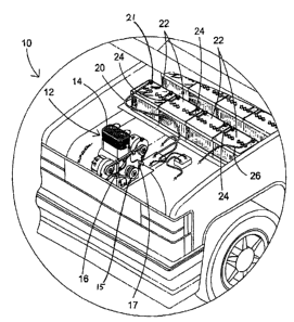
FIG. 1 is an illustrative view of cart charging system of the present
invention in use;
FIG. 2 is an illustrative schematic of the cart charging system of the present
invention;
FIG. 3 is an illustrative view of the power generator of the cart charging
system of the
present invention;
FIG. 4 is an illustrative view of the battery bank of the cart charging system
of the present
invention;
FIG. 5 is an enlarged view of the battery bank of the cart charging system of
the present
invention connected in series;
FIG. 6 is an illustrative view of the distribution system of the cart charging
system of the
present invention; and
FIG. 7 is an electrical schematic of the cart charging system of the present
invention.
DESCRIPTION OF THE REFERENCED NUMERALS
Turning now descriptively to the drawings, in which similar reference
characters denote
similar elements throughout the several views, the Figures illustrate the cart
charging
system of the present invention. With regard to the reference numerals used,
the following
numbering is used throughout the various drawing Figures. 10 cart charging
system of the
present invention 12 power generator 14 generating means 16 alternator 17 belt
18
alternator output 19 lead 20 lead 21 positive pole 22 battery 23 negative pole
24 wire 26
output from battery bank 28 diode 30 junction box 31 controller 32 DC motor 34
Pot box 36
ground 40 voltage control system
8
CA 02622103 2008-02-25
DETAILED DESCRIPTION OF THE PREFERRED EMBODIMENT
The following discussion describes in detail one embodiment of the invention
(and several
variations of that embodiment). This discussion should not be construed,
however, as
limiting the invention to those particular embodiments. Practitioners skilled
in the art will
recognize numerous other embodiments as well. For definition of the complete
scope of the
invention, the reader is directed to appended claims.
Turning now descriptively to the drawings, in which similar reference
characters denote
similar elements throughout the several views, FIGS. 1 through 7 illustrate
the cart charging
system of the present invention indicated generally by the numeral 10.
The battery charging system of the present invention improves on the
shortcomings of
systems of today by providing a charging circuit onboard the vehicle. The
onboard charging
system of the present invention provides means to continuously charge the
batteries without
the need to stop the vehicle. In turn, the range of the electrically powered
vehicle is greatly
increased and down time for external and stationary recharging is greatly
decreased.
The battery charging system of the present invention is comprised of a power
generator, a
distribution system, battery bank, controller and a direct current motor. The
wiring of the
battery charging system provides means for a charging circuit for onboard
electric vehicle
batteries, where the batteries are charged in parallel while being used in
series.
The voltage controller of the present invention's battery charging system
regulates the
voltage to flow maintain necessary current and prevents overcharging of the
batteries.
To accommodate various load capacity needs, the present invention's battery
charging
system provides means for connection to a single power generator or as
necessary, multiple
power generators for increase load capacity.
9
CA 02622103 2008-02-25
FIG. 1 is an illustrative view of cart charging system of the present
invention in use. The
present invention is an onboard charging system for electric vehicles. Prior
art provides
electric vehicles that must be stationary at a charging system to replenish
the current in the
batteries. The range of these electric vehicles is directly proportional to
the charging
capacity of the batteries and the depletion rate of that charge. Factors such
as load and
speed will limit the range of an electric vehicle and increase the frequency
of charging
sessions. The range of an electric vehicle with an onboard charging system is
unlimited as
the batteries are constantly being charged by the present invention.
The cart charging system 10 of the present invention includes a generator 12
having
generating means 14 and a high voltage alternator 16. The generating means 14
includes
output 15 connected to one or more alternators 16 via belt 17. As output 15
rotates,
rotational energy is converted into electrical energy by the high voltage
alternator 16. The
alternator 16 has an output 18 for outputting the induced electrical current
therefrom. The
current output via the output 18 from the alternator 16 is transferred to a
plurality of batteries
22, which form a battery bank. Preferably, the batteries 22 are 12-volt
batteries that are
connected in series to form a battery bank with a battery bank being charged
in parallel by
an appropriately rated alternator. As the batteries 22 are connected in
series, as illustrated
the eiectrical voltage output thereby is 48 voits for each bank with the
system generating 96
volts. The batteries 22 each have a positive pole 21 and a negative pole 23 as
shown
hereinafter with specific reference to FIGS. 4 and 5. The negative pole 23 of
the first battery
22 is connected to the alternator casing via lead 19, which is isolated from
any common
motor ground and thereby each alternator is isolated from all others. The
positive pole 21 of
the first battery is thus connected to the negative pole 23 of the second
battery 22. The third
and fourth batteries 22 are connected in the similar fashion. However, the
final positive pole
21 of the fourth battery 22 is connected to alternator output 18 via lead 20,
for charging
purposes and to voltage controller 31 for distribution purposes. Thereafter,
the current
passes to DC motor 32 for powering the vehicle. As the vehicle is driven,
power from the
battery
CA 02622103 2008-02-25
bank(s) is diminished. However, the generator 12 causes power to be generated
and used
to recharge the individual batteries 22 as needed. The power is provided from
the alternator
16 to the batteries 22 of the battery bank.
FIG. 2 is an illustrative schematic of the cart charging system of the present
invention. The
cart charging system 10 of the present invention includes a generator 12
having generating
means 14 and a high voltage alternator 16. The generating means 14 of the
generator 12 is
preferably a 5 30 horsepower generator that is powered by gas, diesel or
propane. The
generating means 14 includes output 15 connected to one or more alternators 16
via belt
17. As output 15 rotates, rotational energy is converted into electrical
energy by the high
voltage alternator 16. The alternator 16 has an output 18 for outputting the
induced electrical
current therefrom. The current output via the output 18 from the alternator 16
is transferred
to a plurality of batteries 22, which form a battery bank. As previously
described, the
batteries 22 are preferably 12 volt batteries that are connected in series to
form a battery
bank with a battery bank being charged in parallel by an appropriately rated
alternator 16 via
generator output 18. As the batteries 22 are connected in series, as
illustrated the electrical
voltage output thereby is 48 volts for each bank. The batteries 22 each have a
positive pole
21 and a negative pole 23 as shown hereinafter with specific reference to
FIGS. 4 and 5.
The negative pole 23 of the first battery 22 is connected to the aiternator
casing via lead 19,
which is isolated from any common motor ground and thereby each alternator is
isolated
from all others. The positive pole 21 of the first battery is thus connected
to the negative
pole 23 of the second battery 22. The third and fourth batteries 22 are
connected in the
similar fashion. However, the final positive pole 21 of the fourth battery 22
is connected to
alternator output 18 via lead 20, for charging purposes and to voltage
controlfer 31 for
distribution purposes. Thereafter, the current passes to DC motor 32 for
powering the
vehicle. As the vehicle is driven, power from the battery bank(s) is
diminished. However, the
generator 12 causes power to be generated and used to recharge the individual
batteries 22
as needed. The power is provided from the alternator 16 to the batteries 22 of
the battery
bank.
11
CA 02622103 2008-02-25
As shown herein, the charger includes the power generator 12, which
distributes power to
the battery bank(s). The system further includes the voltage controller 31,
pot box 34 and a
direct current motor 32. The alternators 16 are two 48-volt alternators as
required by the four
12-volt batteries forming each battery bank. Furthermore, as shown in FIG. 2
there are two
battery banks. The batteries 22 within each respective bank are connected in
series
determining the voltage output and the two battery banks are connected in
series for
distribution purposes. Thus, as illustrated, each alternator 16 charges four
(4) 12-volt
batteries via generator output 18. Additionally, the alternators are not
grounded to the case
of the motor, as they must be isolated from any common ground. Therefore each
battery
bank is connected to their respective alternator casing via lead 19 and to an
isolated ground
36.
As the generating means 14 generates rotational energy, which is converted
into electrical
energy by each of the alternators 16, the electrical energy is output at the
output 18. A
connection wire connects each of the outputs 18 to a respective positive pole
21 of a battery
in the battery bank. Connected between the output 18 and positive pole 21 is a
diode 28
preventing current feedback into the alternator. At the positive pole 21 of
the final battery in
each battery bank, a further connection wire connects both battery banks at a
junction box
30. From the junction box, an output is connected to a voltage control
mechanism 40, which
ensures proper voltage level exists within the system. The voltage control
mechanism 40
includes a controller 31 and a pot box 34 providing current to the DC motor 32
which in turn
powers the vehicle.
FIG. 3 is an illustrative view of the power generator of the cart charging
system of the
present invention. The cart charging system 10 of the present invention
includes a generator
12 having generating means 14 and a high voltage alternator 16. The generating
means 14
of the generator 12 is preferably a 5 30 horsepower generator that is powered
by gas, diesel
or propane. The generating means 14 includes output 15 connected to one or
more
alternators 16 via belt 17. As output 15 rotates, rotational energy is
converted into electrical
energy by the high voltage alternator 16. The alternator 16 has an output 18
for outputting
the induced
12
CA 02622103 2008-02-25
electrical current therefrom. The current output via output 18 from alternator
16 is used to
charge a plurality of batteries 22 connected in series and charged by the
alternator in
parallel with each series forming a battery bank as shown in FIGS. 1 and 2.
The power generator 12 for the onboard charging system is an internal
combustion engine
and one or more high output alternator 16. A 5 to 30 horsepower gasoline,
diesel or propane
engine rotates output 15 that drives the one or more generators via belt(s) 17
with the
alternator output 18 used to charge an appropriate number of series connected
batteries.
FIG. 4 is an illustrative view of the battery bank of the cart charging system
of the present
invention. The current output via the output 18 from the alternator 16 is
transferred to a
plurality of batteries 22, which form a battery bank. Preferably, the
batteries 22 are 12-volt
batteries that are connected in series to form the battery bank. As the
batteries 22 are
connected in series, the electrical voltage output thereby is 48 volts. The
batteries 22 each
have a positive pole 21 and a negative pole 23 as shown hereinafter with
specific reference
to FIGS. 4 and 5. The negative pole 23 of the first battery 22 is connected
the alternator
housing via lead 19 and an isolated ground 36. The positive pole 21 of the
first battery is
thus connected to the negative pole 23 of the second battery 22. The third and
fourth
batteries 22 are connected in the similar fashion. However, the final positive
pole 21 of the
fourth battery 22 is connected to generator output 18 for charging and to
voltage controller.
Thereafter, the current passes from the bank of batteries to a motor 32 for
powering the
vehicle. As the vehicle is driven, power from the battery bank is diminished.
However, the
generator 12 causes power to be generated and used to recharge the individual
batteries 22
as needed. The power is provided from the alternator 16 to the batteries 22 of
the battery
bank.
Depicted in FIG. 4 are the terminals of four batteries connected in series.
When connected
in series, the output voltage is equivalent to the added sum of each of the
batteries rated
voltage. In turn, four 12-volt batteries wired in series produces an output
voltage of 48 volts.
13
CA 02622103 2008-02-25
FIG. 5 is an enlarged view of series connected batteries. The current output
via the output
18 from the alternator 16 is transferred to a plurality of batteries 22, which
form a battery
bank. Preferably, the batteries 22 are 12-volt batteries that are connected in
series to form
the battery bank. As the batteries 22 are connected in series, the electrical
voltage output is
determined by the number of series connected batteries. In terms of the
present inventions
preferable 12 volt battery four batteries generate 48 volts, 8 batteries
generate 96 volts and
12 batteries generate 144 volts, which are all within the scope of the present
invention with
the determining factor established by the system requirements. The batteries
22 each have
a positive pole 21 and a negative pole 23 as shown hereinafter with specific
reference to
FIGS. 4 and 5. The negative pole 23 of the first battery 22 is connected to
the alternator
case via lead 19 and isolated ground 36. The positive pole 21 of the first
battery is thus
connected to the negative pole 23 of the second battery 22. The third and
fourth batteries 22
are connected in the similar fashion. However, the final positive pole 21 of
the fourth battery
22 is connected to generator out 18 for charging purposes and voltage
controller 31 for
distribution purposes. Thereafter, the current from the bank of batteries is
used to power the
load. In this case, a DC motor 32 for powering the vehicle. As the vehicle is
driven, power
from the battery bank is diminished. However, the generator 12 drives
alternator(s) 16 that
continuously charges the battery bank to recharge the individual batteries 22
as needed.
The power is provided from the alternator 16 to the batteries 22 of the
battery bank.
Depending on the voltage requirements determines the number of batteries
required with
each battery having an alternator or a plurality of appropriately rated
alternators, such as
illustrated in the drawings wherein a 48 volt alternator charges four
batteries connected in
series with the series forming a battery bank charged in parallel.
FIG. 6 is an illustrative view of the distribution system of the cart charging
system of the
present invention. The current output via the output 18 from the alternator 16
is transferred
to a plurality of batteries 22, which form a battery bank. Preferably, the
batteries 22 are 12-
volt batteries that are connected in series to form the battery bank. As the
batteries 22 are
connected in series, the electrical voltage output thereby is 48 volts. The
batteries 22 each
14
CA 02622103 2008-02-25
have a positive pole 21 and a negative pole 23 as shown hereinafter with
specific reference
to FIGS. 4 and 5. The negative pole 23 of the first battery 22 is connected to
the alternator
housing via lead 19 and isolated ground 36. The positive pole 21 of the first
battery is thus
connected to the negative pole 23 of the second battery 22. The third and
fourth batteries 22
are connected in the similar fashion. However, the final positive pole 21 of
the fourth battery
22 is connected to alternator out 18 for charging purposes and voltage
controller 31 for
distribution purposes. Thereafter, the current passes from the bank of
batteries to DC motor
32 for powering the vehicle. As the vehicle is driven, power from the battery
bank is
diminished. However, the generator 12 causes power to be generated and used to
recharge
the individual batteries 22 as needed. The power is provided from the
alternator 16 to the
batteries 22 of the battery bank.
As shown herein, the charger includes the power generator 12, which
distributes power to
the battery bank. The system further includes the voltage controller 31, a
potentiometer 34
and DC motor 32. The alternators 16 are two 48-volt alternators. Furthermore,
as shown in
FIG. 2 there are two battery banks. The batteries 22 within each respective
bank are
connected in series and the two battery banks are connected in parallel. Thus,
each
alternator 16 charges four (4) 12-volt batteries. Additionally, the
alternators are not grounded
to the case of the motor, as they must be isolated from any common ground.
As the generating means 14 generates rotational energy, which is converted
into electrical
energy by each of the alternators 16, the induced electrical energy is output
at the output 18.
A connection wire connects each of the outputs 18 to a respective positive
pole 21.
Connected between the output 18 and the positive pole 21 is a diode 28 to
prevent feedback
into the alternator. As previously stated, the positive pole 21 of the final
battery in each
battery bank, a further connection wire connects both battery banks at a
junction box 30.
From the junction box, an output is connected to a voltage control mechanism
40 for use by
DC motor 32. The voltage control mechanism 40 includes a controller 31 and a
pot box 34
supplying current to the DC motor 32, which in turn powers the vehicle.
CA 02622103 2008-02-25
FIG. 7 is an electrical schematic of the cart charging system of the present
invention. The
present invention can provide multiple alternators and battery banks. FIG. 7
illustrates three
alternators charging individual battery banks of four batteries. The battery
banks are then
connected in series to the controller system junction blocks. An alternate
configuration
includes using one alternator per battery, this can be done with 12, 24 and 48-
volt
alternators.
The current output via the output 18 from the alternator 16 is transferred to
a plurality of
batteries 22, which form a battery bank. Preferably, the batteries 22 are 12-
volt batteries that
are connected in series to form the battery bank. If the batteries 22 are
connected in series,
the electrical voltage output thereby is 144 volts. The batteries 22 each have
a positive pole
21 and a negative pole 23 as shown hereinafter with specific reference to
FIGS. 4 and 5.
The negative pole 23 of the first battery 22 is connected to the generator
housing via lead
19. The positive pole 21 of the first battery is thus connected to the
negative pole 23 of the
second battery 22. The third and fourth batteries 22 are connected in the
similar fashion.
However, the final positive pole 21 of the fourth battery 22 is connected to
generator output
18 for charging purposes and a voltage controller for distribution purposes.
Thereafter, the
current passes from the bank of batteries to DC motor 32 for powering the
vehicle. As the
vehicle is driven, power from the battery bank is diminished. However, the
generator 12
causes power to be generated and used to recharge the individual batteries 22
as needed.
The power is provided from the alternator 16 to the batteries 22 of the
battery bank.
As shown herein, the charger includes the power generator 12 which distributes
power to
the battery bank. The system further includes the voltage controller 31, pot
box 34 and a
direct current motor 32. The alternators 16 are two 48-volt alternators having
the ability to
charge four 12-volt batteries. Furthermore, as shown in FIG. 2 there are two
battery banks.
The batteries 22 within each respective bank are connected in series and the
two battery
banks are connected in series. Thus, each alternator 16 charges four (4) 12-
volt batteries.
Additionally, the alternators are not grounded to the case of the motor, as
they must be
isolated from any common ground.
16
CA 02622103 2008-02-25
As the generating means 14 generates rotational energy, which is converted
into electrical
energy by each of the alternators 16, the electrical energy is output at the
output 18. A
connection wire connects each of the outputs 18 to a respective positive pole
21 of a final
battery in the battery bank. Connected between the output 18 and positive pole
21 is a
charging diode 28. This prevents current feedback into the alternator. At the
positive pole 21
of the final battery in each battery bank, a further connection wire connects
both battery
banks at a junction box 30. From the junction box, an output is connected to a
voltage
control mechanism 40 which ensures proper voltage level exists within the
system. The
voltage control mechanism 40 includes a controller 31 and a pot box 34.
Thereafter, the
current is provided to the DC motor 32 which in turn powers the vehicle.
It will be understood that each of the elements described above, or two or
more together
may also find a useful application in other types of methods differing from
the type described
above.
While certain novel features of this invention have been shown and described
and are
pointed out in the annexed claims, it is not intended to be limited to the
details above, since
it will be understood that various omissions, modifications, substitutions and
changes in the
forms and details of the device illustrated and in its operation can be made
by those skilled
in the art without departing in any way from the spirit of the present
invention.
Without further analysis, the foregoing will so fully reveal the gist of the
present invention
that others can, by applying current knowledge, readily adapt it for various
applications
without omitting features that, from the standpoint of prior art, fairly
constitute essential
characteristics of the generic or specific aspects of this invention.
17