Note: Descriptions are shown in the official language in which they were submitted.
CA 02622137 2008-02-22
09HL 203596
METHOD AND APPARATUS FOR PROVIDING REDUNDANCY IN
MONITORING THE LID SWITCH AND BASKET OF A WASHING MACHINE
FIELD OF INVENTION
The present invention relates generally to washing machines, and more
particularly to washing machine braking system control redundancy.
BACKGROUND OF THE INVENTION
A typical washing machine for washing clothing goes through a wash cycle
which includes a number of modes of operation. Generally, the wash cycle
includes
an agitation mode in which the clothes are agitated in detergent, a rinse
mode, and a
spin mode in which water is removed from the clothes.
Washing machines generally include two components which come into
contact with the clothes, the basket and the agitator. The basket is typically
a
cylindrical container which holds the clothes to be washed and which may have
holes
in its walls to drain the washing liquid (e.g., detergent and water) during
the spin
cycle. The agitator is located within the basket and serves to agitate the
clothes and
the wash liquid in the basket. The combination of the mechanical action of the
agitator
and the chemical action of the wash liquid washes the clothes. The basket and
agitator
are generally located within a second container conventionally known as the
tub. The
tub keeps the wash liquid within the basket during the wash cycle.
To power the agitator and the basket, a conventional induction motor may be
used. The basket and agitator each have drive shafts, which may be concentric,
for
independently driving their respective motions. The agitator drive shaft may
be
connected to the motor through a transmission. The transmission reduces motor
speed
and converts the rotary motion of the motor into an oscillatory output for the
agitator
drive shaft. The basket drive shaft is typically connected to the motor
through the
outer case of the transmission.
- 1 -
CA 02622137 2008-02-22
09HL 203596
During the agitation mode, the basket drive shaft is held stationary while the
agitator drive shaft is oscillated. The basket drive shaft is typically locked
to the
washer frame through a brake and carries the reaction forces from the
transmission
during agitation into the frame. During the spin mode, power is applied to the
basket
drive shaft, and both the agitator and basket drive shafts are rotated
together. During
spin mode, the brake is released so the basket and agitator can be spun up to
a high
speed to expel wash water from the clothes through holes in the basket.
To switch from agitation mode to spin mode, a mode shifter is used. The
mode shifter changes the point of power application from the agitator to the
basket.
An automatic brake is also provided to quickly stop the basket to avoid an
accident if
the washer lid is raised during the spin mode. There are many known ways of
achieving the mode shift and brake functions. A common problem with many
systems
is the level of mechanical complexity of each, which adversely effects cost
and
reliability. There is a need for mode shifters which are more mechanically
simple and
inexpensive. Such systems need to overcome the problems encountered in known
systems while at the same time not creating new problems such as safety
concerns
which would result if the washer fails to shut down when the washer lid is
opened
during operation.
SUMMARY OF THE INVENTION
Consistent with embodiments of the present invention, systems and methods
are disclosed for controlling a mode shifter in a washing machine with a mode
controller. The mode controller facilitates the automatic halting of the
operation of a
washing machine by stopping operation of the washing machine motor. The
washing
machine that implements the method includes a motor controller having a
primary
microprocessor and a secondary microprocessor which serves as a backup
redundancy
processor in the event there is a malfunction with the primary microprocessor
or the
primary microprocessor fails to halt washing machine operation within a
prescribed
window of time. The primary microprocessor controls operation of all of the
washing
machine electrically-controlled components. The secondary microprocessor is
electrically connected to a lid switch and the washing machine motor and is
- 2 -
CA 02622137 2008-02-22
09HL 203596
configured to halt operation of the motor in response to the primary
microprocessor
failing to halt motor operation.
It is to be understood that both the foregoing general description and the
following detailed description are examples and explanatory only, and should
not be
considered to restrict the invention's scope, as described and claimed.
Further,
features and/or variations may be provided in addition to those set forth
herein. For
example, embodiments of the invention may be directed to various feature
combinations and sub-combinations described in the detailed description.
BRIEF DESCRIPTION OF THE DRAWINGS
Non-limiting and non-exhaustive embodiments are described with reference
to the following figures, wherein like reference numerals refer to like parts
throughout
the various views unless otherwise specified.
Figure 1 is a perspective view of an exemplary washing machine with a
portion of a washing machine cabinet removed;
Figure 2 is a schematic sectional view of the washing machine shown in
Figure 1;
Figure 3 is an exemplary embodiment of the motor shown in Figure 2 and
coupled to the motor controller shown in Figure 2;
Figure 4 is an exploded perspective view of the mode shifter shown in Figure
2 coupled to a shaft assembly and the pulley shown in Figure 2;
Figure 5 is a perspective view of the bearing retainer assembly shown in
Figure 4;
Figure 6 is a perspective view of the bracket assembly shown in Figure 4;
Figure 7 is a perspective view of the clutch shown in Figure 4;
Figure 8 is a perspective view of the armature assembly shown in Figure 4;
- 3 -
CA 02622137 2008-02-22
09HL 203596
Figure 9 is a perspective view of the armature assembly shown is Figures 4
and 8 coupled to the drive pulley shown in Figure 4;
Figure 10 is an electrical schematic block diagram of the motor controller
shown in Figure 2 electrically coupled to the motor and the mode shifter; and
Figure 11 is a process flow diagram illustrating operational processing
performed to stop washing machine operation when its lid is opened.
DETAILED DESCRIPTION
The following detailed description refers to the accompanying drawings.
Wherever possible, the same reference numbers are used in the drawings and the
following description to refer to the same or similar elements. While
embodiments of
the invention may be described, modifications, adaptations, and other
implementations are possible. For example, substitutions, additions, or
modifications
may be made to the elements illustrated in the drawings, and the methods
described
herein may be modified by substituting, reordering, or adding stages to the
disclosed
methods. Accordingly, the following detailed description does not limit the
invention.
Instead, the proper scope of the invention is defined by the appended claims.
Consistent with embodiments of the present invention, a method and
apparatus for reducing wiring required to electrically couple components
housed
within a washing machine. The washing machine components are wired and
configured to facilitate a backup breaking system. In one embodiment, a motor
controller is electrically coupled to a motor and a mode shifter housed within
the
washing machine. By coupling the motor controller to the motor and the mode
shifter, additional wiring is not required to electrically couple a washing
machine
control board to the motor and the mode shifter. Further, affixing the motor
controller
to a top portion of the motor reduces an amount of wire that extends between
the
motor controller and the motor and the mode shifter. In a particular
embodiment, the
motor controller is configured to provide a pulse width modulated direct
current
voltage to the mode shifter for facilitating limiting power received by the
made shifter
to a necessary amount of power to prevent or limit mode shifter overheating.
In a
- 4 -
CA 02622137 2008-02-22
09HL 203596
particular embodiment the motor controller includes two microprocessors. A
first
microprocessor serves as the primary processor within the controller. A second
microprocessor serves as a backup redundancy processor to the primary
microprocessor and is configured to monitor a washing machine lid switch and
pulses
within the washing machine motor. In the event that there is a malfunction
with the
primary microprocessor or the primary microprocessor fails to halt the washing
machine motor within a prescribed window of time, the secondary microprocessor
causes the washing machine motor to stop.
The present invention is described below in reference to its application in
connection with and operation of a washing machine. However, it will be
apparent to
those skilled in the art and guided by the teachings herein provided that the
invention
is likewise applicable to any suitable electrical and/or electronic appliance.
Figure 1 is a perspective view of an exemplary washing machine 50
including a cabinet 52 and a cover 54. A portion of cabinet 52 is removed to
show
material features and/or components of washing machine 50. A backsplash 56
extends from cover 54, and a washing machine control board assembly 58 is
coupled
to backsplash 56. A lid 62 is mounted to cover 54 and is movable between an
open
position (not shown) facilitating access to a wash tub 64 located within
cabinet 52,
and a closed position (shown in Figure 1) forming a sealed enclosure over wash
tub 64.
Wash tub 64 includes a bottom wall 66, a sidewall 68, and a basket 70
rotatably mounted within wash tub 64. A pump assembly 72 is located beneath
wash
tub 64 and basket 70 for gravity assisted flow when draining wash tub 64. Pump
assembly 72 includes a pump 74 and a motor 76. A pump inlet hose 80 extends
from
a wash tub outlet 82 in bottom wall 66 to a pump inlet 84, and a pump outlet
hose 86
extends from a pump outlet 88 to a water outlet 90 and ultimately to a
building
plumbing system discharge line (not shown) in flow communication with water
outlet
90.
Further, in the exemplary embodiment, washing machine control board
assembly 58 includes a control panel 92 and a plurality of input selectors 94,
which
- 5 -
CA 02622137 2008-02-22
09HL 203596
collectively form a user interface input for operator selection of machine
cycles and/or
features. In one embodiment, a display 96 indicates selected features, a
countdown
timer, and/or other items of interest to machine users.
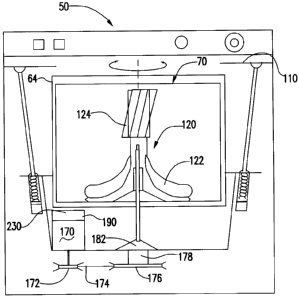
Figure 2 is a schematic view of washing machine 50. Washing machine 50
includes a frame 110 for supporting the components of the washing machine 50,
basket 70 for holding articles such as clothes to be washed, and an agitator
120 for
agitating the clothes in basket 70. In one embodiment, agitator 120 is molded
with a
plastic material, such as polypropylene, and includes a plurality of vanes
122. Vanes
122, which are typically flexible, mechanically agitate the clothes back and
forth
within the basket. In a particular embodiment, washing machine 50 includes an
auger
124 at the top of agitator 120. Auger 124 further enhances the movement of the
clothes within basket 70. Basket 70 and agitator 120 sit within wash tub 64,
which
retains the wash water during the wash cycle.
To power washing machine 50 a motor 170, such as a 3-phase motor, is
provided. Motor 170 is coupled to the basket 70 and agitator 120 through a
motor
pulley 172, a belt 174, a drive pulley 176, a mode shifter 178, and basket and
agitator
drive shafts. Mode shifter 178 enables motor 170 to execute an agitation mode
and a
spin mode.
A motor controller 190 is affixed to a top portion of motor 170. In the
exemplary embodiment, motor controller 190 is independently electrically
coupled to
motor 170 and mode shifter 178 for facilitating providing power to and
operating
motor 170 and/or mode shifter 178. Motor controller 190 is also electrically
coupled
to washing machine control board assembly 58 such that input into washing
machine
control board assembly 58 manipulates or controls operation of motor 170
and/or
mode shifter 178. Because motor controller 190 is coupled to motor 170, the
present
invention facilitates reducing wiring within washing machine 50. Specifically,
only
the wires that electrically couple washing machine control board assembly 58
to
motor controller 190 are required to extend from washing machine control board
assembly 58 to a lower portion of washing machine 50. Further, the amount of
wire
needed to electrically couple motor controller 190 to motor 170 and mode
shifter 178
- 6 -
CA 02622137 2008-02-22
09HL 203596
is reduced. As such, an amount of wiring throughout washing machine 50 is
reduced.
Controller 190 includes a plurality of electrical components and two
microprocessors.
A first microprocessor controls operation of all washing machine operational
components. A second microprocessor serves as a backup microprocessor that
monitors the washing machine lid switch and the RPM of the motor 170. The RPM
is monitored via Hall Effect sensors. When the shaft of motor 170 is rotating
primary
microprocessor 414 and a secondary microprocessor 420 are receiving an
indication
of such rotations. The secondary microprocessor is configured to halt movement
of
the motor 170 and thereby the basket 70 and agitator 120 by disabling the
washing
machine 50 when its operation is not stopped by microprocessor 414 within a
predetermined amount of time.
Mode shifter 178 includes an inductive power solenoid, described in detail
below, which enables motor 170 to execute an agitation mode and a spin mode.
In one
embodiment, during the agitation mode, mode shifter 178 is energized to couple
motor 170 to agitator 120. As such, only agitator 120 is rotated during the
agitation
mode. Further, during the spin mode, mode shifter 178 is deenergized to couple
both
basket 70 and agitator 120 to motor 170. As such, agitator 120 and basket 70
are
rotated during the spin mode.
Figure 3 is an exemplary embodiment of motor 170 affixed to motor
controller 190. In one embodiment, motor controller 190 is affixed to a top
portion
200 of motor 170. In this embodiment, motor 170 is a 3-phase motor. In
alternative
embodiments, motor 170 is any motor suitable for operating washing machine 50
as
described herein. Motor controller 190 includes a circuit board 210 having a
plurality
of electronic components 220 coupled thereto, as described in greater detail
below in
reference to Figure 10. The electrical components 220 include at least a
primary
microprocessor 222 and a backup microprocessor 224 which serves as a
redundancy
monitor of the washing machine lid switch 422 and the pulses from the Hall
Effect
sensors within the motor controller 190. A shield 230 is coupled to motor
controller
190 and acts as a heat sink for motor controller 190. Further, shield 230
prevents or
limits water within washing machine 50 from contacting motor controller 190.
- 7 -
CA 02622137 2008-02-22
09HL 203596
Figure 4 is an exploded perspective view of mode shifter 178 coupled to
drive pulley 176 and a shaft assembly 300. Specifically, shaft assembly 300
includes
an agitator shaft 302, a spin tube 304, and bearing retainer assembly 182, as
is shown
in Figure 5. Mode shifter 178 includes a solenoid 306, a clutch 308, a spring
310, and
a washer 312. Solenoid 306 includes a bracket assembly 314 and an armature
assembly 316.
Drive pulley 176 is coupled to agitator shaft 302, which extends though spin
tube 304 and is movable with respect to spin tube 304. In this embodiment, a
spacer
armature 318 and a retaining ring 320 are coupled between drive pulley 176 and
agitator shaft 302. Agitator shaft 302 is coupled to agitator 120 and spin
tube 304 is
coupled to basket 70. Bearing retainer assembly 182 is positioned
circumferentially
around spin tube 304 and is coupled within washing machine 50. Bearing
retainer
assembly 182 includes dogs or other suitable projections for retaining basket
70
properly positioned during the agitation mode. Bearing retainer assembly 182
is also
coupled to solenoid bracket assembly 314, which includes an inductive coil 322
positioned therein, as shown in Figure 6.
Clutch 308 is coupled to spin tube 304 and armature assembly 316. In one
embodiment, a plurality of splines 324 formed on an outer surface of clutch
308, as
shown in Figure 7, engage or interfere with a plurality of splines 326 formed
on an
inner surface of armature assembly 316, as shown in Figure 8. Splines 324 and
splines 326 are engaged such that armature assembly 316 can slide between a
upper
position and a lower position. Specifically, armature assembly 316 is
positioned
within a bore 328 formed in bracket assembly 314 such that energizing and
deenergizing an inductive current in inductive coil 322 causes armature
assembly 316
to slide along clutch 308 between the upper position and the lower position.
With inductive coil 322 energized, armature assembly 316 is in the upper
position. In the upper position, armature assembly 316 is configured to couple
to
bearing retainer assembly 182. Specifically, a plurality of teeth 330 formed
on
armature assembly 316, as shown in Figure 8, are configured to engage or
cooperate
with a plurality of teeth 332 formed on bearing retainer assembly 182, as
shown in
- 8 -
CA 02622137 2008-02-22
09HL 203596
Figure 5. With inductive coil 322 deenergized, armature assembly 316 moves
into the
lower position. In the lower position, a plurality of teeth 334 formed on
armature
assembly 316, as shown in Figure 8, engage or cooperate with a plurality of
notches
336 formed in drive pulley 176, as shown in Figure 9. Washer 312 and spring
310 are
coupled between armature assembly 316 and clutch 308 for facilitating movement
of
armature assembly 316 with respect to clutch 308. Specifically, spring 310 is
configured to provide a resistant force against armature assembly 316 as
armature
assembly 316 moves into the upper position.
In one embodiment, during operation of washing machine 50, solenoid 306 is
energized by motor controller 190. In the energized state, armature assembly 3
16 is
in the upper position. In the upper position, armature assembly 316 is
disengaged
from drive pulley 176 and engaged with bearing retainer assembly 182. As such,
bearing retainer assembly 182 prevents armature assembly 316 from rotating
such that
basket 70 does not rotate. Motor controller 190 powers motor 170 causing drive
pulley 176 to rotate. The rotation of drive pulley 176 rotates agitator shaft
302 such
that only agitator 120 rotates when solenoid 300 is energized, referred to
herein as the
agitation mode for washing machine 50.
When the spin mode of washing machine 50 is required, motor controller 190
deenergizes solenoid 306 causing armature assembly 316 to slide into the lower
position. In the lower position, armature assembly 316 is engaged with drive
pulley
176. Drive pulley 176 rotates to rotate agitator shaft 302 causing agitator
120 to
rotate. Because armature assembly 316 is engaged with drive pulley 176,
armature
assembly 316 also rotates causing clutch 308 to rotate. The rotation of clutch
308
causes spin tube 304 and basket 70 to rotate such that agitator 120 and basket
70
rotate together in the spin mode.
As described above, in one embodiment, washing machine 50 operates in a
spin mode when solenoid 306 is deenergized, and operates in an agitation mode
when
solenoid 306 is energized. In an alternative embodiment, washing machine 50
operates in a spin mode when solenoid 306 is energized, and operates in an
agitation
mode when solenoid 306 is deenergized.
- 9 -
CA 02622137 2008-02-22
09HL 203596
Figure 10 is an electrical schematic block diagram of motor controller 190
electrically coupled to motor 170 and mode shifter 178. In one embodiment,
motor
controller 190 includes a power inlet 400 including an inrush and transient
protection
component 402 and an AC/DC converter 404. AC/DC converter 404 converts a
single phase AC line to direct current. A portion of the direct current is
stored in a
DC power supply 406, and a portion of the direct current is channeled to a
direct
current bus 408. Direct current bus 408 is electrically coupled to a mode
shifter
control and monitor 410, which is coupled to and controls mode shifter 178.
Direct
current bus 408 is also electrically coupled to insulated gate bipolar
transistors (IGBT)
412, which convert the direct current into a synthetic AC voltage known as
pulse
width modulation. In this embodiment, the pulse width modulation is used to
power
motor 170.
Motor controller 190 also includes a microprocessor 414 that is powered by
DC power supply 406 and operated by a communications interface 416 that is
electrically coupled to washing machine control board assembly 58.
Microprocessor
414 also operates a gate driver 418 which is powered by DC power supply 406
and
provides an electrical interface between microprocessor 414 and IGBT 412. Gate
driver 418 also functions to provide a hardware trip current limit for washing
machine
50. As such, microprocessor 414 controls the pulse width modulation pattern
based on
factors including, but not limited to, speed reference, tachometer 544
feedback, DC
link current, and/or DC link voltage. Further, microprocessor 414 monitors a
heat
sink temperature of motor controller 190.
Moreover, microprocessor 414 monitors a lid switch 422, and operates a
brake control 424 including a brake resistor and drip shield 426. If the lid
62 on a
washing machine 50 is opened during operation, safety requires that washing
machine
operations be terminated immediately. This is necessary to prevent an injury
which
may be caused if a person sticks a hand or any other object into the machine
tub
during washing machine operation. Lid
switch 422 transmits a signal to
microprocessor 414 if the lid is opened while the washing machine 50 is
operating.
This causes the microprocessor 414 to transmit a signal that stops operation
of
-10-
CA 02622137 2008-02-22
09HL 203596
washing machine 50 while the lid remains open. Specifically, microprocessor
414
transmits a control signal to the brake control 424 in order to stop operation
of
washing machine 50. Brake control 424 also stops washing machine 50 when the
hardware trip current limit of gate driver 418 is exceeded. In addition,
microprocessor
414 monitors and operates mode shifter control and monitor 410 to operate mode
shifter 178.
In one embodiment, mode shifter 178 is coupled to direct current bus 408.
As such, only a necessary amount of power is channeled to mode shifter 178.
Specifically, mode shifter 178 requires a first amount of power to become
energized.
After mode shifter 178 is energized, a second amount of power is required to
maintain
the energized state. In one embodiment, the first amount of power is greater
than the
second amount of power. Thus, mode shifter 178 receives a larger amount of
power
while being energized than an amount of power needed to maintain mode shifter
178
in the energized state. By reducing the amount of power channeled to mode
shifter
178 after mode shifter 178 is energized, an amount of heat generated by mode
shifter
178 is reduced.
It is recognized that in any mechanical device there is the possibility that a
part could become defective or the software controlling a processor could
become
defective. Any such failure could result in the microprocessor 414 not being
able to
process the signal received from the lid switch 422 and the washing machine 50
continuing to operate while the lid 62 remains open, creating a hazardous
condition.
In order to compensate for such a possibility, the motor controller 190
includes a
secondary processor 420, which is powered by DC power supply 406. Secondary
processor 420 is a backup microprocessor that monitors the lid switch 422 and
RPM
of the motor via Hall Effect sensors 430 and is configured to halt movement of
the
basket 70 and agitator 120 by disabling the washing machine 50 when its
operation is
not stopped by primary microprocessor 414 within a predetermined amount of
time.
Should there be any failure by primary microprocessor 414 to stop the motor
170,
basket 70, or agitator 120, for example the primary microprocessor 414 does
not sense
the transition because of a microprocessor malfunction, or, there is a
mechanical
-11-
CA 02622137 2008-02-22
OW-IL 203596
failure such as the belt 174 is slipping on the pulley; secondary
microprocessor 420
transmits signals to stop motor operation and thereby the basket 70 and
agitator 120.
Even if primary microprocessor 414 is trying to halt operation of the washing
machine, if such efforts fail, then the secondary processor 420 stops
operation through
disabling the motor 170 by disabling gate driver 418, which is powered by DC
power
supply 406. Disabling gate driver 418 disables IGBT chips 412. Gate drivers
418 are
enabled until disabled by primary microprocessor 414 or secondary processor
420.
In one embodiment, a method for assembling a washing machine is provided.
The method includes providing a mode shifter including a solenoid, coupling a
basket
and an agitator to the mode after, and coupling a motor to the mode shifter.
The
solenoid selectively allows the motor to rotate the basket and/or the
agitator. The
method also includes affixing a motor controller to the motor, and
electrically
coupling the motor controller to each of the mode shifter and the motor. The
motor
controller is in operational control communication with the mode shifter and
the motor.
Figure 11 is a process flow diagram illustrating the flow of information and
control signals within motor controller 190 when a lid switch 540 indicates
that the
washing machine lid has been opened. When the lid switch 540 is opened, both
the
primary microprocessor 542 and the secondary microprocessor 570 are aware of
this
change because the primary microprocessor 542 and the secondary microprocessor
570 are both continuously monitoring the lid switch. The primary
microprocessor 542
and the secondary microprocessor 570 are also aware of the speed of the motor
through electrical connection to a hall sensor 544. The primary microprocessor
542
receives a signal based on the feedback from the DC bus voltage and checks to
determine if the DC bus voltage is greater than 420 volts 546. When the DC bus
voltage is less than 420 volts the brake resistor remains off 548. When the DC
bus
voltage is greater than 420 volts the brake resistor is turned on 550 in order
to
dissipate the braking energy regenerated to the DC bus.
During operation, the primary processor 542 creates a break wave form
which turns the gate drivers on and off 552 in order to enable the IGBT' s to
switch the
motor current 554. This process causing the motor to be driven slightly slower
than
- 12 -
CA 02622137 2008-02-22
09HL 203596
the rotor is turning and thereby creates a braking torque 556 causing the DC
bus
voltage to increase due to regeneration. The processor is constantly sensing
the DC
bus voltage to determine if the DC bus voltage is greater than 420 volts 546.
The
mechanical elements such as the belt apply the braking torque along with the
motor in
order to stop the drum within a predetermined period of time. In one
embodiment, the
period of time in which the drum may me stopped is within seven seconds 560.
When the lid switch opens, the main microprocessor 542 determines if the
speed of the motor is less than or equal to forty-five RPMs at any time before
a
predetermined time window passes. In one embodiment, the predetermined time
window is twenty-five seconds after the lid is opened. It is contemplated that
the
RPM value for which the main microprocessor 542 is checking within the
predetermined window may be set to values other than forty-five RPMs. If the
motor
speed is less than or equal to forty-five RPMs at any time following twenty-
five
seconds after the lid is opened 564, then no action is taken 568. If the motor
speed is
greater than forty-five RPMs at any time following twenty-five seconds after
the lid is
opened 564, the primary microprocessor sets a brake error flag and no signal
to gate
drivers is transmitted and thereby no power is transmitted to the motor.
The secondary microprocessor 570 is constantly monitoring the speed of the
motor along with the primary microprocessor 542 in order to determine if the
speed of
the motor is less than or equal to forty-five RPMs at any time before a
predetermined
time window passes. In one embodiment, the predetermined time window is twenty-
five seconds after the lid is opened. It is contemplated that the RPM value
for which
the secondary microprocessor 570 is checking within the predetermined window
may
be set to values other than forty-five RPMs. If the motor speed is less than
or equal to
forty-five RPMs at any time following twenty-five seconds after the lid is
opened 572,
then no action is taken 576. If the motor speed is greater than forty-five
RPMs at any
time following twenty-five seconds after the lid is opened 572, the secondary
microprocessor 570 disables the enable line of the gate drivers in order to
prevent
application of power to the motor and thereby requiring service before power
may be
restored to the motor.
- 13 -
CA 02622137 2014-05-06
09HL 203596
The above-described system for powering a mode shifter of a washing
machine allows a motor controller to be affixed to a motor and electrically
coupled to
both the motor and the mode shifter. More specifically, the system facilitates
efficiently and cost-effectively coupling components of a washing machine
thereby
reducing an amount of wire used in the washing machine. Further, the system
facilitates powering the mode shifter with a direct current voltage such that
the mode
shifter only receives a necessary amount of power and avoids overheating. As a
result, a more efficient and more easily maintainable washing machine is
provided.
Exemplary embodiments of a method and an apparatus for controlling a
mode shifter for a washing machine are described above in detail. The method
and
apparatus are not limited to the specific embodiments described herein, but
rather,
steps of the method and/or components of the apparatus may be utilized
independently and separately from other steps and/or components described
herein.
Further, the described method steps and/or apparatus components can also be
defined
in, or used in combination with, other methods and/or apparatus, and are not
limited to
practice with only the method and apparatus as described herein.
As used herein, an element or step recited in the singular and proceeded with
the word "a" or "an" should be understood as not excluding plural elements or
steps,
unless such exclusion is explicitly recited. Further, references to one
embodiment"
of the present invention are not intended to be interpreted as excluding the
existence
of additional embodiments that also incorporate the recited features.
While there have been described herein what are considered to be preferred
and exemplary embodiments of the present invention, other modifications of
these
embodiments falling within the scope of the invention described herein shall
be
apparent to those skilled in the art.
- 14 -