Note: Descriptions are shown in the official language in which they were submitted.
CA 02622435 2008-03-13
WO 2007/034147 PCT/GB2006/003427
ENERGY ABSORBER
This invention relates to an energy absorber, for example
for use with a safety cable attached to a structure such as
an electricity pylon and used in conjunction with a fall
arrest device. However, it will be noted the energy
absorber can be used in a vertical, horizontal or inclined
configuration and on a variety of structures.
To ensure the safety of a person (user) climbing a
structure, for example an electricity pylon, a safety
system is used in which the user is attached to a safety
cable by way of a fall arrest device which is movable along
the cable. The safety cable is attached by a structural
anchor in the region of the top of the structure.
In the event of a fall, the fall arrest device will lock
onto the cable thereby arresting the fall of the user.
However, in the event of a fall, a relatively high load is
applied to the structure and to the falling user via the
attachment of the safety cable to the structure. The load
at the structural anchor can be significantly higher than
the load on the user, especially in multi-user fall
situations.
An energy absorber is known in which a rod or the like of
metal is pulled through a die to absorb energy by
deformation of the metal in the event of a fall in order to
minimise the load applied to the user and to the structure.
Such an energy absorber is adequate to absorb energy
resulting from the fall of a single user. However, the
known energy absorber is not adequate to minimise the load
applied to the structure in a reliable and predictable
CA 02622435 2008-03-13
WO 2007/034147 PCT/GB2006/003427
- 2 -
manner in the event of several users falling at the same
time.
There is a need for an energy absorber for use with a
safety cable which minimises the load applied to a
structure in the event of a fall of one or more users from
the structure and which provides energy absorption in a
reliable and predictable manner.
It is therefore an object of the present invention to
provide an energy absorber which overcomes or minimises
these problems.
According to the present invention there is provided an
energy absorber, for use with a safety cable attached to a
structure, the energy absorber comprising an elongate slide
member and a friction plate positioned adjacent to the
elongate slide member, wherein the friction plate is urged
against a face of the elongate slide member by a biasing
means to generate friction between the friction plate and
the elongate slide member.
The friction plate may be of phosphor bronze.
A retaining member may be provided to retain the friction
plate in position adjacent to the elongate slide member.
The retaining member may be adapted to connect the
remainder of the energy absorber to a fixing bracket for
attachment to the structure. Alternatively, the energy
absorber may be attached directly to the structure.
Isolating material, adapted to minimise galvanic reaction,
may be provided between the retaining member and the
remainder of the energy absorber. The isolating material
CA 02622435 2008-03-13
WO 2007/034147 PCT/GB2006/003427
- 3 -
may be a plastics material, for example a hardwearing
plastics material.
Retaining means, for example a shoulder, may be provided on
the friction plate and adapted to retain the friction plate
within the retaining member. The retaining member may be
provided with an aperture configured to receive the
retaining means of the friction plate.
The biasing means may be in the form of a spring, such as
a coil spring.
The biasing means may be in the form of a pair of coaxially
arranged springs with a second spring arranged coaxially
within a first spring.
The biasing means may be positioned between the friction
plate and an end plate. Adjusting means may be provided to
adjust a spacing between the friction plate and the end
plate to compress the biasing means to a predetermined
length and/or torque.
At least one pair of friction plates may be provided
wherein the friction plates are urged against opposite face
of the elongate slide member by the biasing means. A
plurality of pairs of friction plates may be provided.
The at least one pair of friction plates may be secured to
each other by securing means passing through an elongate
aperture in the elongate slide member. The elongate
aperture may be linear or non-linear. A guide member, for
example a cylindrical guide member, may extend through the
elongate aperture to guide the friction plate along the
slide member.
CA 02622435 2008-03-13
WO 2007/034147 PCT/GB2006/003427
- 4 -
An aperture may be provided in an end of the elongate slide
member to facilitate the attachment of a cable to the
elongate slide member.
For a better understanding of the present invention and to
show more clearly how it may be carried into effect
reference will now be made, by way of example, to the
accompanying drawings in which:
Figure 1 is an exploded perspective view of a first
embodiment of an energy absorber according to the present
invention together with a fixing bracket;
Figure 2 is a plan view of the energy absorber shown in
Figure 1 attached to the fixing bracket;
Figure 3 is a perspective view of the energy absorber shown
in Figure 1 attached to the fixing bracket;
Figure 4 is an exploded perspective view of a second
embodiment of an energy absorber according to the present
invention together with a fixing bracket;
Figure 5 is a plan view of the energy absorber shown in
Figure 4 attached to the fixing bracket; and
Figure 6 is a perspective view of the energy absorber shown
in Figure 4 attached to the fixing bracket.
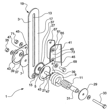
Figures 1 to 3 show a first embodiment of an energy
absorber 1 according to the present invention for use on a
structure, for example an electricity pylon. The energy
absorber comprises an elongate plate-like slide member 3
and friction plates 5, 7 which are urged against the
elongate slide member 3 by biasing means 9, 11.
CA 02622435 2008-03-13
WO 2007/034147 PCT/GB2006/003427
- 5 -
The elongate slide member 3, preferably of 316 grade
stainless steel, has an elongate slot 13, for example 100
mm in length, therethrough. The elongate slot 13 is within
the elongate slide member 3 and extends along a
longitudinal axis of the elongate slide member 3. A through
hole 15 is provided adjacent to an end on the elongate
slide member 3, lowermost in the figures, to provide a
means of attaching the elongate slide member 3 to a cable
(not shown), for example by means of a clevis. The elongate
slot 13 could be linear or non-linear.
A first circular friction plate 5 is positioned against a
first face 17 of the elongate slide member 3 and a second
circular friction plate 7 is positioned against a second
face 19 of the elongate slide member 3, the second face
opposing the first face. The friction plates 5, 7 are
preferably of phosphor bronze. A cylindrical peg 21 passes
through a central hole in the first friction plate 5,
through the elongate slot 13 in the elongate slide member
3 and through a central hole in the second friction plate
7 to secure the friction plates 5, 7 together.
Friction is created between first faces (nearest to the
elongate slide member 3) of the friction plates 5, 7 and
the elongate slide member 3 by first biasing means 9 in the
form of a first stainless steel coil spring and by second
biasing means 11 in the form of a second stainless steel
coil spring, the springs 9, 11 being positioned between a
second face 27 (furthest from the elongate slide member 3)
of the first friction plate 5 and a circular end plate 29.
The second spring is of smaller diameter than the first
spring and is position coaxially within the first spring.
The second, inner, spring is maintained in the coaxial
position by means of a cylinder 31 which passes axially
through the interior of the second spring 11.
CA 02622435 2008-03-13
WO 2007/034147 PCT/GB2006/003427
- 6 -
A threaded securing means 33, in the form of an elongate
bolt, passes through a central hole in the end plate 29,
through the cylinder 31 within the second spring 11,
through the peg 21 positioned through the elongate slot of
the elongate slide member and between the first and second
friction plates, and extends outwards therefrom.
Consequently, the slot enables the elongate slide member to
move slidably relative to the securing means 33 and the
components mounted thereon.
A head on the securing means 33 prevents the securing means
from passing completely through the hole in the end plate
29. A fastening means 35, for example a fastening nut, is
threadingly attached to the portion of the securing means
extending outwardly from the second friction plate 7 such
that the coaxial springs 9, 11 are compressed between the
second face of the first friction plate 5 and the circular
end plate 29. Compression of the coaxial springs urges the
first faces of the friction plates against the elongate
slide member creating friction therebetween which resists
relative movement between the friction plates 5, 7 and the
elongate slide member 3.
Washers are positioned between the head of the securing
means and the end plate 29, and between the second face of
the second friction plate 7 and the fastening means 35.
The first face of each friction plate, adjacent to the
elongate slide member 3, has a diameter greater than the
opposing second face such that a shoulder 37 is provided
around the circumference of the friction plate.
Plate-like retaining members 39 are provided either side of
the elongate slide member 3 to connect the energy absorber
to a fixing bracket 41 (as described hereinafter) by way of
CA 02622435 2008-03-13
WO 2007/034147 PCT/GB2006/003427
- 7 -
the friction plates 5,7. Each retaining member 39 has an
aperture 43 with a diameter corresponding to the diameter
of the second face of a friction plate. Consequently, each
friction plate is retained within the aperture 43 of the
retaining member 39 but is prevented from passing through
the aperture in a direction away from the elongate slide
member 3 by the circumferential shoulder 37 of the friction
plate. Alternatively, the friction plate could be formed
with an annular groove for seating the spring 9 and which
would also prevent lateral movement of the friction plate.
Each retaining member 39 has a pair of protrusions 45,
coplanar with the plane of the retaining member, the
protrusions extending beyond an edge of the elongate slide
member 3. A through hole 47 is provided in each protrusion
45. The positions of the through holes in one pair of
protrusions correspond to complementary holes through the
other pair of protrusions, that is each through hole in one
pair of protrusions is coaxial with a corresponding through
hole in the other pair of protrusions.
As shown in Figure 2, the plate-like fixing bracket 41,
referred to hereinbefore, is formed of two angled plates
which together form an "M" shaped cross-section in which
four plate-like arms 51, 53, 55, 57 are arranged to form
three ridges 59, 61, 63. The length of each of the arms is
substantially identical. The angle subtended at a ridge
between two adjacent arms is substantially 90 degrees.
Each component of the bracket 41 is formed with an
attachment member 49 which extends outwards from the ridge
61 formed between the two innermost arms 53, 55 of the
fixing bracket 41 along the length of the ridge. The
attachment member 49 is parallel, in use, to the
CA 02622435 2008-03-13
WO 2007/034147 PCT/GB2006/003427
- 8 -
longitudinal axis of the elongate slide member 3 of the
energy absorber 1.
Through holes 65 are provided in the attachment members 49,
the holes 65 being positioned to correspond to the position
of the holes 47 through the protrusions 45 of the retaining
members 39.
A pair of holes 67 is also provided through each of the two
outermost arms 51, 57 of the fixing bracket 41 to enable
the fixing bracket 41 to be secured around a portion of a
pylon (not shown).
The first retaining member and the second retaining member
of the energy absorber 1 are secured together, with one
retaining member either side of the elongate slide member
3. The attachment members 49 of the fixing bracket 41 are
positioned between the retaining members 39 and secured in
position by securing means 69, preferably bolts. The
securing means 69 passes through the holes 47 in the
protrusions 45 of the retaining members and the holes 65 in
the attachment members 49, and is fastened by fastening
means 71, for example fastening nuts. Consequently, the
energy absorber 1 is secured in position relative to the
fixing bracket 41 attached to the portion of the pylon.
Pylons are generally galvanised and painted to avoid
galvanic corrosion problems. In order further to reduce the
risk of corrosion, the energy absorber 1 is isolated from
the pylon by means of isolating bushes 73 provided through
the holes in the attachment members 49 of the fixing
bracket 41 to minimise the possibility of a galvanic
reaction between the pylon and the energy absorber 1. The
isolating bushes 73 are made of DELRIN, an insulating
CA 02622435 2008-03-13
WO 2007/034147 PCT/GB2006/003427
- 9 -
Nylon-type polymer which is hardwearing and resistant to UV
degradation, or an equivalent material.
In use, the fixing bracket 41 is positioned at the top of
a pylon. Adjacent faces of the innermost arms 53, 55 of the
fixing bracket '41 are positioned against a portion of a
strut of the pylon. The fixing bracket 41 is secured in
position relative to the strut of the pylon by securing
means passing through the holes provided through each of
the two outermost arms 51, 57 of the fixing bracket 41 and
passing around the body of the strut as it is not
permissible to drill fixing holes in the struts of the
pylon. Other means of clamping to the pylon or structure
could be used.
Once the fixing bracket 41 is secured to the pylon, the
energy absorber 1 is attached to the fixing bracket 41 by
the securing means 69 passing through the retaining members
39 and the attachment members 49 of the fixing bracket 41
as described hereinbefore.
The friction plates 5, 7 are urged against the elongate
slide member 3 of the energy absorber 1 by tightening the
fastening means 35 threadingly attached to the portion of
the securing means 33 extending outwardly from the second
friction plate 7 until a predetermined compression of the
coaxial springs 9, 11 is achieved between the second face
27 of the first friction member and the end plate 29. As
the spring constant is known, the predetermined compression
can be achieved by rotating the fastening means relative to
the thread of the securing means until a predetermined
length of spring is achieved. Shims may be used to
determine the length of the springs 9, 11 when compressed
in order that the predetermined length can be achieved.
CA 02622435 2008-03-13
WO 2007/034147 PCT/GB2006/003427
- 10 -
Alternatively, the predetermined compression could be
achieved by rotating the fastening means relative to the
thread of the securing means until a predetermined value of
torque is achieved.
A safety cable is attached to the through hole 15 provided
adjacent to the end on the elongate slide member 3 as
described hereinbefore. The cable is connected to a
tensioning unit (not shown) attached to a lower portion of
the pylon situated at a relatively short distance from the
ground on which the pylon is positioned. The tensioning
unit is adapted to tension the cable with a predetermined
tensioning force of, for example, 1 kN. Consequently a
tensioned cable, to which a user can attach himself,
extends down the pylon.
In the event of the user falling while at a height on the
pylon, the user, via the attachment to the tensioned cable,
will exert a downward force on the lowermost region of the
elongate slide member 3 of the energy absorber 1 as the
safety cable is deflected from a rest position. The
elongate slide member will pivot about a longitudinal axis
of the coaxial springs 9, 11 such that the longitudinal
axis of the elongate slot 13 is parallel to the downward
direction of the applied force.
Due to the predetermined compression of the springs 9, 11
and the friction plates 5, 7 being urged against the
elongate slide member 3, the rate of sliding movement of
the elongate slide member 3 relative to the friction plates
will be reduced in a predictable manner by the friction.
Consequently energy created by the fall of the user is
converted into energy to overcome the friction between the
friction plates and the elongate slide member 3 so
CA 02622435 2008-03-13
WO 2007/034147 PCT/GB2006/003427
- 11 -
absorbing energy which may otherwise have been transferred
to the pylon and the user.
The length and form of the elongate slot 13 in the elongate
slide member 3 and the predetermined compression of the
springs are selected so as to reduce the force when
arresting a falling user to less than 6kN.
It should be appreciated that the inner spring 9 could be
positioned within the outer spring 11 by a relatively short
locating cylindrical member provided at each end of the
inner spring 9 to align the springs relative to each other
rather than by the central cylinder 31 described
hereinbefore.
Different springs could be used if it was desirable to
absorb energy at different rates.
It should further be appreciated that the length of the
elongate slot 13 in the elongate slide member 3 could be
greater than 100 mm if a greater mass, for example a number
of users, was to be attached to the energy absorber 1 or
springs with different spring constants could be used if it
was desirable to absorb energy at different rates.
Although, it has been described hereinbefore that the
energy absorber 1 is attached to the fixing bracket 41 by
a securing means 39 passing through the attachment members
49 of the fixing bracket 41, the energy absorber 1 could be
fastened to the fixing bracket 41 or by any other suitable
fixing means.
Figures 4 to 6 show a second embodiment of an energy
absorber 1 in accordance with the present invention in
which two sets of circular friction plates 5, 7 are
CA 02622435 2008-03-13
WO 2007/034147 PCT/GB2006/003427
- 12 -
provided. The two sets of friction plates are arranged
adjacent to each other along the longitudinal axis of the
elongate slide member.
Similar features to those in the first embodiment have been
given corresponding reference numbers.
The arrangement of two sets of friction plates urged
against the elongate slide member increases the friction
that can be produced and/or provides more surface area
between which friction can be generated.
As can be seen in Figure 4, a single spring 9 is provided
between a first friction plate 5 and an end plate 29 for
each set of friction plates. However it should be
appreciated that a coaxial arrangement of two springs could
be used as shown in Figures 1 to 3. The advantage of the
coaxial spring arrangement is that it provides a greater
spring force in a given area.
The retaining members are provided with a pair of
apertures, arranged parallel to the longitudinal axis of
the elongate slide member, to accommodate the presence of
two sets of friction plates.
The energy absorber 1 shown in Figures 4 to 6 is mounted on
a pylon, and used, as explained for the energy absorber
shown in Figures 1 to 3.
It should be appreciated that the energy absorber 1 shown
in Figures 4 to 6 could incorporate additional features
from the energy absorber shown in Figures 1 to 3.
An energy absorber in accordance with the present invention
could be provided with a casing, for example a weather-
CA 02622435 2008-03-13
WO 2007/034147 PCT/GB2006/003427
- 13 -
resistant casing, to protect the components of the energy
absorber from the environment. An aperture would be
provided in a lower region of the casing to permit the
safety cable attached to the through hole 15 of the
elongate slide member 3 to be connected to the tensioning
unit attached to a lower portion of the structure. The
aperture would also be dimensioned to permit the lowermost
end of the elongate slide member to exit the casing in the
event of a user falling whilst attached to the tensioned
cable.