Note: Descriptions are shown in the official language in which they were submitted.
CA 02622444 2014-03-07
- 1 -
REFRIGERATED AND ILLUMINATED SHOWCASE
BACKGROUND OF THE INVENTION
1. Field of the Invention
[0001]
The present invention relates to a showcase in which
a display chamber is formed in an insulating wall to
display commodities in the display chamber while cooling
the commodities. More particularly, it relates to lights
in the display chamber.
2. Description of the Related Art
[0002]
Heretofore, as this type of showcase, for example,
there has been an open showcase 100 disclosed in Patent
Document 1 and shown in FIG. 10. FIG. 10 shows a vertical
side view of the conventional open showcase 100. In this
open showcase 100, cold air is discharged from a discharge
port 103 formed in an upper edge of an opening 102 of an
insulating wall 101 having a substantially U-shaped section
toward a suction port 104 of a lower edge of the opening
102, whereby a cold air curtain is formed in the opening
102. In consequence, the inside of a display chamber 105
surrounded with the insulating wall 101 is cooled to a
predetermined temperature. Then, a plurality of
fluorescent lamps 108 are attached to a canopy 107
positioned outside the upper edge of the opening 102,
opposite side edges of the opening 102 and lower surfaces
CA 02622444 2008-02-22
- 2 -
of front parts of shelves 106 to illuminate the inside of
the display chamber 105 and the showcase 100 itself.
[Patent Document 11 Japanese Patent Application
Laid-Open No. 5-146346
[0003]
However, in the conventional open showcase 100, the
fluorescent lamps 108 are used as light devices, and the
fluorescent lamps 108 are provided on an upper front part
of the display chamber 105, the lower surfaces of the
shelves 106 disposed in the display chamber 105 and the
like, so that there has been a problem that a thermal load
is generated in the display chamber 105 owing to the
fluorescent lamps 108. A usual fluorescent lamp converts
electric energy into visible radiation, infrared radiation
and ultraviolet radiation to radiate a visible ray for use
as the light. In this case, a thermal loss is generated,
and hence there is a problem that the inside of the display
chamber 105 is heated by not only the fluorescent lamps
themselves but also radiant heat of the fluorescent lamps.
[0004]
Therefore, in a cooling showcase in which the inside
of the display chamber 105 is cooled to the predetermined
temperature, a cooling operation is performed in
consideration of a thermal load due to the light, so that a
cooling efficiency lowers. In consequence, there has been
a problem that steep rise of running cost is incurred.
Commodities displayed in the display chamber 105 are
CA 02622444 2008-02-22
- 3
irradiated with an ultraviolet ray, so that there is a
problem that the commodities are adversely affected.
[0005]
Furthermore, the fluorescent lamps have a problem
that flicker is generated owing to use of an alternating
current, so that there is a problem that eyes are adversely
affected.
[00061
In addition, to attach the fluorescent lamps 108 in
the display chamber 105, components such as sockets and
stabilizers are required. Therefore, in attachment
positions, attachment places for not only the fluorescent
lamps but also the sockets, stabilizers and the like need
to be secured. The fluorescent lamps have to be connected
to wires in order to supply power to the lamps. There are
problems that assembly operability is deteriorated and that
increase of the number of the components and steep rise of
production cost are incurred.
[0007]
In recent years, a thickness of the whole shelves
106 tends to be reduced for a purpose of improving a
display efficiency in the display chamber 105. In actual,
there is a problem that a thickness dimension of each shelf
106 is limited by the fluorescent lamp provided under the
shelf 106.
[0008]
Moreover, a replacement operation of the fluorescent
CA 02622444 2008-02-22
- 4 -
lamps 108 is forcibly required owing to luminance decrease
and light defect caused with elapse of years. Therefore, a
user is forced to perform the replacement operation of the
fluorescent lamps 108, and the operation disadvantageously
becomes laborious. The new fluorescent lamp 108 for
replacement needs to be always prepared, and a storage
place of the fluorescent lamp 108 needs to be secured.
Furthermore, the fluorescent lamp 108 contains mercury,
resulting in a problem that the used fluorescent lamp 108
cannot easily be discarded.
SUMMARY OF THE INVENTION
[0009]
The present invention has been developed in order to
solve a conventional technical problem, and an object
thereof is to provide a showcase provided with a light
device in which a maintenance operation can be simplified
and a cooling efficiency in a display chamber can be
improved.
[0010]
In a showcase according to the present invention, a
display chamber is formed in an insulating wall to display
commodities on a plurality of steps of shelves disposed in
the display chamber and cool the commodities, and the
showcase is characterized by comprising LED lights which
illuminate the inside of the display chamber from the
upside, and light guide plates provided on lower surfaces
CA 02622444 2008-02-22
- 5 -
'
of the shelves, light inlet portions of the light guide
plates being provided so as to protrude forward from the
shelves, a light emitting surface of each light guide plate
facing the shelf under the shelf provided with the light
guide plate.
[0011]
A showcase according to the invention of a second
aspect is characterized in that in the above invention,
cold air is discharged from a cold air discharge port
provided in an upper edge of a front surface opening of the
display chamber, and sucked into a cold air suction port
provided in a lower edge of the opening, to form a cold air
curtain in the front surface opening of the display chamber,
the showcase further comprises a canopy which protrudes
forward from an upper front end of the insulating wall; and
a reflective plate provided on an inner side of the canopy
and positioned before the cold air discharge port, the LED
lights being attached to the reflective plate, the front
surface opening of the display chamber being irradiated
with light emitted from the LED lights.
[0012]
According to the present invention, the showcase in
which the display chamber is formed in the insulating wall
to display the commodities on the plurality of steps of
shelves disposed in the display chamber and cool the
commodities comprises the LED lights which illuminate the
inside of the display chamber from the upside, and the
ak 02622444 2008-02-22
- 6 -
,
light guide plates provided on the lower surfaces of the
shelves. The light inlet portions of the light guide
plates are provided so as to protrude forward from the
shelves, and the light emitting surface of each light guide
plate faces the shelf under the shelf provided with the
light guide plate. In consequence, the LED lights which
illuminate the inside of the display chamber from the
upside can directly illuminate the inside of the display
chamber from the upside, and the shelf under the shelf
provided with the light guide plate can be illuminated with
the light emitted from the LED lights via the light guide
plate provided on the lower surface of the shelf.
[0013]
In consequence, the inside of the display chamber
can be illuminated from the upside only with the LED lights
which illuminate the inside of the display chamber from the
upside, the shelves can be illuminated from the upside, and
the whole inside of the display chamber can effectively be
illuminated.
[0014]
In particular, the shelf provided with the light
guide plate on the upside thereof is illuminated with the
light emitted from the LED lights to enter the light inlet
portion of the light guide plate and then emitted from the
light emitting surface of the light guide plate provided so
as to face the shelf. Therefore, any light fixture does
especially not have to be provided, this obviates the need
ak 02622444 2008-02-22
- 7
for sockets, wires and the like, and a constitution of the
shelves can be simplified.
[0015]
In consequence, a thermal load in the display
chamber can be reduced, and the commodities can be
illuminated without being heated. Moreover, a thermal load
in the display chamber due to the lights can be reduced, so
that lowering of a cooling efficiency of the showcase
itself can be prevented in advance, and running cost of the
showcase itself can be reduced.
[0016]
According to the invention of the second aspect, in
addition to the above invention, the cold air is discharged
from the cold air discharge port provided in the upper edge
of the front surface opening of the display chamber, and
sucked into the cold air suction port provided in the lower
edge of the opening, to form the cold air curtain in the
front surface opening of the display chamber, the showcase
further comprises the canopy which protrudes forward from
the upper front end of the insulating wall; and the
reflective plate provided on the inner side of the canopy
and positioned before the cold air discharge port, the LED
lights are attached to the reflective plate, and the front
surface opening of the display chamber is irradiated with
the light emitted from the LED lights. In consequence, the
LED lights can effectively illuminate the whole inside of
the display chamber from the upper front part of the
ak 02622444 2011-02-03
- 8 -
display chamber.
[0017]
Furthermore, the LED lights are provided outside the
cold air curtain, whereby the thermal load concerning the
lights in the display chamber can be zeroed, and the
lowering of the cooling efficiency of the showcase itself
due to the thermal load can be prevented in advance. In
consequence, the running cost of the whole showcase can be
reduced.
According to an aspect of the present invention there
is provided a showcase to display commodities, the showcase
comprising:
an insulating wall around a display chamber;
a plurality of steps of shelves disposed inside the
display chamber, the shelves extending in a forward
direction from an inside of the display chamber toward an
open side of the display chamber;
a cold air discharge port provided in an upper edge of
a front surface opening of the display chamber, and a cold
air suction port provided in a lower edge of the opening,
to form a cold air curtain in the front surface opening of
the display chamber;
LED lights which illuminate the inside of the display
chamber from above; and
light guide plates disposed on lower surfaces of the
shelves,
wherein the light guide plates comprise respective
light ray inlet portions that protrude forward from forward
ak 02622444 2014-03-07
- 8a -
ends of the shelves in respective positions to accept light
rays from the LED lights, and
wherein each light guide plate comprises a light
emitting surface located under the respective shelf
provided with the light guide plate.
According to another aspect of the present invention,
there is provided a refrigerated and illuminated showcase
to display commodities, the showcase comprising:
an insulating wall around a display chamber;
a plurality of steps of shelves disposed inside the
display chamber, the shelves extending in a forward
direction from an inside of the display chamber toward an
open side of the display chamber;
a cold air discharge port provided in an upper edge of
a front surface opening of the display chamber, and a cold
air suction port provided in a lower edge of the opening,
to form a cold air curtain in the front surface opening of
the display chamber;
LED lights which illuminate the inside of the display
chamber from above;
light guide plates disposed on lower surfaces of the
shelves;
a canopy which protrudes forward from an upper front
end of the insulating wall; and
a reflective plate provided on an inner side of the
canopy and positioned before the cold air discharge port,
wherein the LED lights are attached to the reflective
plate,
wherein the front surface opening of the display
chamber is irradiated with light emitted from the LED
lights,
CA 02622444 2014-03-07
- 8b -
wherein the light guide plates comprise respective
light ray inlet portions that protrude forward from forward
ends of the shelves in respective positions to accept light
rays from the LED lights, and
wherein each light guide plate comprises a light
emitting surface located under the respective shelf
provided with the light guide plate.
BRIEF DESCRIPTION OF THE DRAWINGS
FIG. 1 is a perspective view of an open showcase to
which the present invention is applied;
FIG. 2 is a vertical side view of the open showcase
shown in FIG. 1;
FIG. 3 is a partially enlarged sectional view of FIG.
2;
FIG. 4 is a sectional view of a shade;
FIG. 5 is a diagram showing an attached state of LED
lights;
FIG. 6 is a diagram showing a result of illuminance
measurement;
FIG. 7 is a vertical side view of a showcase used in
the illuminance measurement of FIG. 6;
FIG. 8 is an enlarged sectional view of a shelf plate
front part;
CA 02622444 2008-02-22
- 9
FIG. 9 is an enlarged sectional view of a handle
rail part; and
FIG. 10 is a vertical side view of a conventional
open showcase.
DESCRIPTION OF THE PREFERRED EMBODIMENT
[0018]
Next, an embodiment of the present invention will be
described in detail with reference to the drawings. FIG.
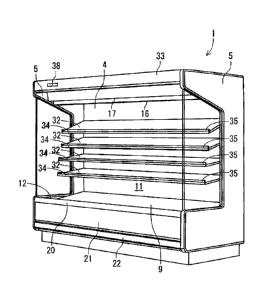
1 shows a perspective view of an open showcase 1 to which
the present invention is applied, and FIG. 2 shows a
vertical side view of the open showcase 1 shown in FIG. 1,
respectively. The open showcase 1 is a vertical open
showcase to be installed in a store such as a supermarket,
and is constituted of an insulating wall 2 opened in a
front surface and having a substantially U-shaped section,
and insulating side plates 5, 5 attached to side surfaces
of the insulating wall 2 in an installation spot.
[0019]
A partition plate 4 and another partition plate (not
shown) are attached on an inner side of the insulating wall
2 of the open showcase 1 so that a space is formed between
the wall and each partition plate, and two inner and outer
layer ducts are formed between the insulating wall 2 and
the partition plate 4 and the like. A bottom plate 9 is
attached to a front part of a lower end of a back partition
plate 10 constituting the inner partition plate so that a
CA 02622444 2008-02-22
- 10 -
space for the duct is secured between the bottom plate and
a bottom wall 2A of the insulating wall 2. A display
chamber 11 is formed on inner sides of the partition plate
4 and the bottom plate 9.
[0020]
Moreover, in this display chamber 11, a pair of
brackets 31 are attached to a support (not shown) of a back
part in the display chamber 11 so that heights and
attachment angles of the brackets can be changed, and a
plurality of steps of shelf plates 32 each including the
brackets to constitute a shelf together are disposed.
Price rails 34 molded of a hard synthetic resin are
attached to front edges of the shelf plates 32, and the
price rails 34 also serve as decorative members of the
shelf plates 32. A predetermined space is formed between a
front wall of each shelf plate 32 and the price rail 34,
and a guard 35 for preventing commodities on the shelf
plate 32 from dropping down is attached to the space.
[0021]
It is to be noted that in the present embodiment,
the shelf plates 32 are constituted of a transparent
material having a light transmission property, for example,
a glass plate or an acryl plate. The shelf plates 32
constituted of the transparent material have a
predetermined strength. In addition, the brackets 31 for
attaching the shelf plates 32 to the supports, the price
rails 34, the guards 35 and the like may similarly be
Mk 02622444 2008-02-22
=
- 11 -
,
constituted of a transparent material.
[0022]
An inner layer discharge port 16 and an outer layer
discharge port 17 to which honeycomb materials 13, 14 are
attached, respectively, are arranged in an upper edge of a
front surface opening 12 of the insulating wall 2, and
these inner layer discharge port 16 and outer layer
discharge port 17 communicate with the inner layer duct and
the outer layer duct, respectively. An inner layer suction
port 18 and an outer layer suction port 19 are arranged in
a lower edge of the opening 12.
[0023]
On the other hand, a plurality of blowers (not
shown) for the inner layer duct and the outer layer duct
are installed on the bottom wall 2A of the insulating wall
2 in a rear part under the bottom plate 9.
[0024]
A cooler 39 of a cooling device is vertically
provided in the inner layer duct behind the back partition
plate 10. In a case where the blower disposed for the
inner layer duct is operated, cold air which has performed
heat exchange between the air and the cooler is raised in
the inner layer duct, and discharged from the inner layer
discharge port 16 toward the inner layer suction port 18.
Then, the cold air sucked from the inner layer suction port
18 is again accelerated by the blower.
[0025]
ak 02622444 2008-02-22
,
- 12 -
On the other hand, in a case where the blower
disposed for the outer layer duct is operated, air in the
outer layer duct is raised in the outer layer duct, and
discharged from the outer layer discharge port 17 toward
the outer layer suction port 19. Then, the air sucked from
the outer layer suction port 19 is again accelerated by the
blower. In consequence, double front and rear air curtains
are formed in the opening 12, and the air of a part of the
=
inner cold air curtain is circulated through the display
chamber 11 to cool the display chamber 11.
[0026]
On the other hand, a hand rail 20 provided over the
whole width of the lower edge of the opening 12 of the open
-showcase 1 is attached to an upper surface of a lower front
wall 2C of the insulating wall 2. A front surface lower
panel 21 is attached to the front surface of this front
wall 2C so as to continue to the hand rail 20, and a bumper
22 is attached under the front surface lower panel 21 so
that a plane of the bumper is the same as that of the front
surface lower panel 21.
[0027]
Next, a constitution of a front part of a ceiling
wall 2B of the insulating wall 2 will be described with
reference to FIGS. 3 to 5. FIG. 3 shows a partially
enlarged sectional view of FIG. 2, FIG. 4 is an enlarged
sectional view of a shade 46, and FIG. 5 is a diagram
showing an attached state of LED lights 40.
ak 02622444 2008-02-22
,
- 13 -
[0028]
A canopy 33 which protrudes forward is attached to a
front end (an upper part front end) of the ceiling wall 2B
of the insulating wall 2, and a reflective plate 45 is
attached to an inner side of the canopy 33 so that the
reflective plate protrudes externally from the front
surface opening 12 of the display chamber 11. It is to be
noted that a temperature indicator 38 is provided on the
front surface of the canopy 33 as shown in FIG. 1.
[0029]
This reflective plate 45 is constituted of a metal
plate decorated with painting, and a front part of the
plate is provided with a light attachment portion 41 which
is recessed over a longitudinal direction. This light
attachment portion 41 opens toward the front surface
opening 12 of the display chamber 11 positioned in a rear
part under the light attachment portion, and front and rear
edges of the light attachment portion 41 are formed to
slightly tilt toward the opening in a direction in which
the edges come close to each other.
[0030]
Then, the surface of this light attachment portion
41 which faces the opening is a light attachment surface
41A, and the surface is disposed at an angle opposed to the
front surface opening 12 of the display chamber 11 from an
upper front part, that is, the surface is constituted so as
to face the display chamber 11 in an obliquely rear part
ak 02622444 2008-02-22
- 14 -
under the light attachment surface. The LED lights 40 are
attached to the light attachment surface 41A.
[0031]
The plurality of LED lights 40 are attached to
substrates 42 which extend in the longitudinal direction at
predetermined intervals. The substrates 42 provided with
the LED lights 40 are fixed via a plurality of fixing
screws 43 ... in a state in which the substrates abut on
the light attachment surface 41A. It is to be noted that
the LED lights 40 for use in the present embodiment are of
a chip type of white LED light (product number NS6W083T)
manufactured by Nichia Corporation. One line or two front
and rear lines or more of LED lights 40 may be arranged,
and in the present embodiment, two lines of LED lights are
provided. In the present embodiment, the front surface
opening 12 of the open showcase 1 is formed so as to extend
as long as six shaku (about 1830 mm), so that about 108 LED
lights 40 are used.
[0032]
Moreover, the light attachment surface 41A of the
reflective plate 45 to which the LED lights 40 are attached
is provided with a plurality of exhaust holes 44 disposed
over the longitudinal direction as shown in FIG. 5.
[0033]
Then, the light attachment surface 41A of the light
attachment portion 41 is covered with a shade 46 attached
so as to surround the LED lights 40, the substrates 42 and
CA 02622444 2008-02-22
- 15 -
the exhaust holes 44 from the downside. The shade 46 has a
shape curved at such a predetermined curvature as to
protrude toward the front surface opening 12 of the display
chamber 11. It is to be noted that the shade 46 is fitted
into the light attachment portion 41 of the reflective
plate 45, whereby the shade is detachably attached. FIG. 5
shows a state in which the shade 46 is attached to a part
of the light attachment portion 41.
[0034]
This shade 46 is constituted of a colorless
transparent material having a light transmission property.
In the present embodiment, to diffuse light from the LED
lights 40 toward the front surface opening 12 of the
display chamber 11, the surface of the shade which faces
the LED lights 40 is formed to be flat and smooth, and an
outer surface 46A of the shade 46 is formed into a wave-
like section or a sawtooth-like section as shown in FIG. 4.
[0035]
In consequence, light traveling rectilinearly in
parallel from the LED lights 40 enters the shade 46, is
then refracted in multiple directions by the outer surface
46A formed into the waveform section or the sawtooth-like
section, and can be diffused in a broad region.
[0036]
According to such a constitution, when the LED
lights 40 are lit, the irradiation light of the LED lights
40 diffused in the shade 46 can effectively illuminate the
ak 02622444 2008-02-22
- 16
whole inside of the display chamber 11 from an upper front
part positioned outside the display chamber 11.
[0037]
Here, a case where the inside of the display chamber
11 is illuminated with the conventional fluorescent lamps
is compared with a case where the inside of the display
chamber 11 is illuminated with the LED lights 40 as in the
present embodiment with reference to experiment results of
FIG. 6. In such an experiment, the same showcase except
the lights is used for comparison. As experiments using
the conventional fluorescent lamps, there are shown two
types of experiments including an experiment in which T10
fluorescent lamps (02 mm) are used in a canopy, a ceiling
board of a chamber and lower surfaces of front parts of
four shelves 106 as shown in FIG. 10 and an experiment in
which T5 tube (4)16 mm) fluorescent lamps are used. On the
other hand, as an experiment using the LED lights 40 as in
the present embodiment, an experiment is shown in which one _
line of the LED lights 40 are attached to the canopy 33 as
shown in FIG. 7.
[0038]
Then, the four shelves were disposed in the display
chamber of each open showcase 1, and commodities S were
mounted on an upper front end of each shelf, followed by
measuring illuminance of the light for irradiating the face
of each commodity was irradiated. It is to be noted that
the face of the commodity S on the top shelf is point A,
ak 02622444 2008-02-22
- 17 -
the face of the commodity S on the second shelf is point B.
the face of the commodity S on the third shelf is point C,
and the face of the commodity S on the fourth shelf is
point D.
[0039]
According to this measurement, with regard to the
illuminance of each point in a case where the T10
fluorescent lamps were used, the illuminance of the point A
was 1260 LX, that of the point B was 830 LX, that of the
point C was 600 LX, and that of the point D was 600 LX.
With regard to the illuminance of each point in a case
where the T5 tube fluorescent lamps were used, the
illuminance of the point A was 1800 LX, that of the point B
was 1300 LX, that of the point C was 700 LX, and that of
the point D was 470 LX. It is seen that in the positions
other than the point D, the illuminance of the T5 tube
fluorescent lamp is high as compared with a case where the
T10 fluorescent lamp is used.
[0040]
On the other hand, in a case where the LED lights 40
were attached to the reflective plate 45 on the inner side
of the canopy 33 as in the present embodiment, the
illuminance of the point A was 2380 LX, that of the point B
was 1520 LX, that of the point C was 1000 LX, and that of
the point D was 812 LX. Therefore, it is seen that in any
point, the illuminance of the light for irradiating the
commodities mounted on the shelves is high in a case where
ak 02622444 2008-02-22
- 18 -
the LED lights 40 are used as compared with a case where
the fluorescent lamps are used as in the conventional
example.
[0041]
Moreover, when the total demands of lighting in the
above-mentioned cases are compared, the total demand of
lighting is 468 W in the case where the T10 fluorescent
lamps are used, it is 356 W in the case where the T5 tube
fluorescent lamps are used, and it is 198 W in the case
where the LED lights 40 are used. Assuming that the demand
of the case where the T10 fluorescent lamps are used is 100,
the demand of the T5 tube fluorescent lamps is 76%, and the
demand of the LED lights 40 is 42%.
[0042]
Therefore, in a case where the LED lights 40 are
used in illuminating the display chamber 11 as in the
present embodiment, an equal or more lighting effect can be
produced as compared with a case where light devices such
as the plurality of fluorescent lamps are provided in the
display chamber as in the conventional example. Therefore,
even in a constitution in which the shelf plates 32 are not
provided with self-emitting light fixtures, for example, a
constitution in which light fixtures such as the
fluorescent lamps are not provided on lower surfaces of the
shelf plates 32 or the like, commodities to be displayed on
the shelf plates 32, especially milk packages, plastic
bottled beverages and the like are mounted in uprising
CAB, 02622444 2008-02-22
= - 19 -
states, and faces of the commodities which face the front
surface opening 12 of the display chamber 11 can
effectively be illuminated.
[0043]
This obviates the need for the light fixtures on the
shelf plates 32, whereby power leakage due to dew
condensation can be prevented. This can also obviate the
need for components to be attached to the lights, for
example, sockets for attaching these light fixtures,
stabilizers and the like. A constitution of the shelves
can be simplified. Moreover, the number of the components
can be reduced, so that productivity can be improved.
[0044]
Moreover, the LED lights 40 attached to the
reflective plate 45 of the canopy 33 can produce the
lighting effect similar to that produced in the case where
light devices such as the plurality of fluorescent lamps
are provided in the display chamber as in the conventional
example, so that power consumption of the whole open
showcase 1 can remarkably be reduced.
[0045]
Furthermore, the LED lights 40 do not radiate any
harmful ultraviolet ray or heat ray to the commodities
displayed in the display chamber 11, so that the
commodities can be illuminated without being heated. In
particular, the LED lights 40 which generate heat are
provided on the inner side of the canopy 33 which protrudes
CA 02622444 2008-02-22
- 20
forward from the upper front end of the insulating wall 2,
so that the inside of the display chamber 11 is illuminated
from the outside of the display chamber 11, that is, from
the outside of the cold air curtain. Therefore, a thermal
load concerning the lighting in the display chamber 11 can
be zeroed, and lowering of the cooling efficiency of the
showcase 1 itself can be prevented in advance. In
consequence, running cost of the whole showcase 1 can be
reduced.
[0046]
Moreover, it is possible to avoid a disadvantage
that the commodities are adversely affected by the harmful
ultraviolet ray of the lights. In consequence, the
commodities can be displayed while fresher states thereof
are maintained.
[0047]
On the other hand, the substrates 42 provided with
the LED lights 40 are attached so as to abut on the
reflective plate 45 constituted of a metal plate so that
heat exchange between the substrates and the reflective
plate can be performed. Therefore, exhaust heat generated
from the substrates 42 of the LED lights 40 is transmitted
to the reflective plate 45, whereby a heat release effect
of the reflective plate 45 can be obtained. In consequence,
the heat generated from the substrates 42 of the LED lights
40 can smoothly be released.
[0046]
CA 02622444 2008-02-22
- 21 -
Furthermore, in the =LED lights 40, unlike the
heretofore used fluorescent lamps, any flicker is not
generated, so that stable lights can be obtained, and the
commodities can appropriately be illuminated. In addition,
the LED lights 40 can easily be dimmed. Therefore, the
dimming is performed in accordance with the commodities to
be displayed in the display chamber 11, whereby further
effective lighting can be performed.
[0049]
Moreover, the LED lights 40 has a remarkably long
life period as compared with the fluorescent lamp, and this
can obviate the need for a replacement operation of the
lights. Therefore, this can obviate the need for a
laborious operation such as storage of replacement
components or a treatment of wastes discharged owing to the
replacement.
[0050]
Furthermore, in the present embodiment, the light
traveling rectilinearly in parallel from the LED lights 40
can be diffused in the multiple directions by the shade 46
which covers the LED lights 40 and which has a light
transmission property, so that the front surface opening 12
of the display chamber 11 can be irradiated with the light
from the LED lights 40 in a broad region. The whole inside
of the display chamber 11 can effectively be illuminated
even with the LED lights 40 from one direction.
[0051]
ak 02622444 2008-02-22
- 22 -
In consequence, the commodities displayed so as to
be opposed to the front surface opening 12 of the display
chamber 11, especially the milk packages, the plastic
bottled beverages and the like are mounted in the upright
states, and the faces of the commodities which face the
front surface opening 12 of the display chamber 11 can be
illuminated with the light emitted from the LED lights 40
diffused via the shade 46. Therefore, the lighting effect
of the commodities can be improved.
[0052]
Moreover, in the present embodiment, the outer
surface 46A of the shade 46 on a side opposite to the LED
lights 40 is formed into the wave-like section or the
sawtooth-like section. Therefore, the outer surface of the
shade 46 formed into the wave-like section or the sawtooth-
like section functions as a prism, and can refract, reflect
and diffuse the light traveling rectilinearly in parallel
from the LED lights in the multiple directions. The broad
region can be irradiated with the light emitted from the
LED lights by the shade.
[0053]
Therefore, as described above, the light from the
LED lights 40 can produce a lighting effect equal to or
more than that produced in the case where light devices
such as the plurality of fluorescent lamps are provided in
the display chamber as in the conventional example.
[0054]
CA 02622444 2008-02-22
- 23 -
Moreover, in the present embodiment, the shelf
plates 32 and the like of the shelves disposed in the
display chamber 11 are constituted of the transparent
material as described above. Therefore, the shelves
constituted of the transparent material are irradiated from
above with the light emitted from the LED lights 40, and
then the light passes through the shelves, whereby the
light emitted from the LED lights 40 can travel through the
whole display chamber 11 without being disturbed by the
shelves, and the lighting effect of the whole display
chamber 11 can be improved.
[0055]
Therefore, according to such a constitution, the
commodities on the shelves can be illuminated without
providing any special light fixture on the shelf plates 32.
This can obviate the need for the components to be attached
to the lights, for example, the sockets for attaching these
light fixtures and the like, and the constitution of the
shelves can be simplified.
[0056]
Moreover, in addition to the shelf plates 32 and the
like constituted of the transparent material, as shown in
FIG. 8, the shelf plate 32 may be constituted of a
heretofore used steel plate material, and a light guide
plate 48 may be attached to a lower surface of the shelf
plate 32. This light guide plate 48 is constituted of, for
example, an acryl resin or the like, and attached to the
ak 02622444 2008-02-22
- 24
whole lower surface of the shelf plate 32 in a state in
which the light guide plate slightly protrudes forward
(toward the LED lights 40) from a front end of the shelf
plate 32 (the whole shelf including the price rail 34 and
the like). The front end of the light guide plate 48
disposed so as to protrude forward from the shelf plate 32
is provided with a light inlet portion 49. The ray inlet
portion 49 is configured to receive the light from the LED
lights 40 and reflect the light rearward.
[0057]
On the other hand, the surface of the light guide
plate 48 which faces the lower surface of the shelf plate
32 is provided with a plurality of grooves, scratches and
the like for irregularly reflecting the derived light, and
a reflective sheet 50 is attached to the corresponding
surface. Then, a diffusion sheet 51 is attached to the
surface of the light guide plate 48 opposite to the lower
surface of the shelf plate 32, that is, a light emitting
surface 52.
[0058]
According to such a constitution, the inside of the
display chamber 11 is illuminated from above with the LED
lights 40, whereby the light emitted from the LED lights 40
is struck on the light inlet portion 49 of the light guide
plate 48 provided so as to protrude forward from each shelf
plate 32. In consequence, the light derived rearward from
the light inlet portion 49 is irregularly reflected by the
ak 02622444 2008-02-22
- 25 -
=
scratches formed on the surface of the light inlet portion
on the side of the lower surface of the shelf plate 32, and
the reflective sheet 50, and the light is then diffused by
the diffusion sheet 51 on the facing light emitting surface
52, and emitted. Therefore, the irradiation light from the
LED lights 40 is emitted from the light emitting surface 52
of the light guide plate 48 provided on the whole lower
surface of the shelf plate 32 via the light guide plate 48.
=
[0059]
Therefore, the diffused light is radiated from the
light emitting surface 52 of the light guide plate 48,
whereby the whole upper surface of the shelf plate 32
positioned under the shelf plate 32 provided with the light
guide plate 48 so as to face the shelf plate is illuminated.
Therefore, the inside of the display chamber 11 can be
illuminated from above only with the LED lights 40 which
illuminate the inside of the display chamber 11 from above.
Moreover, not only the faces of the commodities mounted on
the shelf plates 32 but also the commodities mounted on
rear parts of the shelf plates 32 can be illuminated. In
consequence, the whole inside of the display chamber 11 can
effectively be illuminated.
[0060]
In particular, to illuminate the shelf plate 32
provided with the light guide plate 48 disposed above the
shelf plate, the light emitted from the LED lights 40 and
struck on the light inlet portion 49 of the light guide
ak 02622444 2008-02-22
- 26 -
plate 48 is emitted from the light emitting surface 52 of
the light guide plate 48 disposed so as to face the shelf
plate 32. Therefore, the light fixtures do not have to be
especially disposed. This obviates the need for the
sockets, wires and the like, and hence the constitution of
the shelves can be simplified.
[0061]
It is to be noted that in the present embodiment,
the light guide plate 48 is provided Over the whole lower
surface of the shelf plate 32, but the present invention is
not limited to such a constitution as long as the light
guide plate is formed so as to extend along a depth
dimension from a front side of the shelf plate 32.
[0062]
Moreover, in addition to the constitution of the LED
lights 40 provided on the inner side of the canopy 33 or
instead of the constitution of the LED lights 40, it may be
constituted that the inside of the display chamber 11 may
be illuminated with the LED lights 40 from a lower front
part of the display chamber 11.
[0063]
In such a case, as shown in FIG. 9, the hand rail 20
of the above embodiment is constituted of a hand rail main
body 24 provided over the whole width of the lower edge of
the front surface opening 12 of the open showcase 1, a
reflective plate 26 provided on an upper surface of the
hand rail main body 24 so as to extend over the whole width
CA 02622444 2008-02-22
- 27 -
'
of the lower edge of the opening 12, and a front surface
upper panel 25 which covers the front surface of the hand
rail main body 24 from an upper end of the body, and the
LED lights 40 are attached to the reflective plate 26.
[0064]
The reflective plate 26 is constituted of a metal
plate, and arranged so as to perform heat exchange between
the reflective plate and the hand rail main body 24 or the
front surface upper panel 25 similarly constituted of the
metal plate. It is to be noted that, for example, an
aluminum material having a high heat exchange efficiency is
used in the metal plate for use in the reflective plate 26.
Then, an upper surface of the reflective plate 26 is
provided with a light attachment portion 26A which is
= recessed over the longitudinal direction, in the same
manner as in the reflective plate 45. Front and rear edges
of this light attachment portion 26A are provided with
engagement claws 26B for detachably attaching a shade 53.
[0065]
Then, the surface of this light attachment portion
26A which faces the opening is a light attachment surface
26C, and the surface is disposed at an angle opposed to the
front surface opening 12 of the display chamber 11 from a
lower front part, that is, the surface is constituted so as
to face the display chamber 11 in an obliquely rear part
above the light attachment surface. The LED lights 40
having a constitution similar to that of the LED lights
CAB, 02622444 2008-02-22
- 28
attached on the inner side of the canopy 33 are attached to
the light attachment surface 26C.
[0066]
Then, the light attachment surface 26C of the light
attachment portion 26A is covered with a shade 53 attached
so as to surround the LED lights 40 and the like from the
upside. The shade 53 has a shape curved at such a
predetermined curvature as to protrude toward the front
surface opening 12 of the display chamber 11. It i to be
noted that front and rear ends of the shade 53 are fitted
into the engagement claws 26B of the light attachment
portion 26A of the reflective plate 26, whereby the shade
is detachably attached. It is to be noted that a
constitution of the shade 53 is substantially the same as
that of the shade 46, and hence detailed description
thereof is omitted.
[0067]
According to such a constitution, when the LED
lights 40 are lit, the irradiation light of the LED lights
40 diffused by the shade 53 can effectively illuminate the
whole inside of the display chamber 11 from a lower front
position outside the display chamber 11.
[0068]
Therefore, even in such a constitution, even when
light fixtures such as the fluorescent lamps are not
provided on the lower surfaces of the shelf plates 32
provided in the display chamber 1]. and the like, the faces
ak 02622444 2008-02-22
- 29 -
,
of the commodities displayed on the shelves can effectively
be illuminated in the same manner as in the case where the
LED lights 40 are attached to the inner side of the canopy
33 as described above. Therefore, this obviates the need
for the light fixtures on the shelves, whereby the power
leakage due to the dew condensation can be prevented. This
can also obviate the need for the components to be attached
to the lights, for example, the sockets for attaching these
light fixtures, the stabilizers and the like, and the
constitution of the shelves can be simplified.
[0069]
Moreover, the LED lights 40 attached to the
reflective plate 26 can produce a lighting effect similar
to that produced in the case where light devices such as
the plurality of fluorescent lamps are provided in the
display chamber 11 as in the conventional example, so that
the power consumption of the whole showcase can remarkably
be reduced.
[0070]
Furthermore, even in this case, the LED lights 40
are provided outside the cold air curtain, whereby the
thermal load concerning the lighting in the display chamber
11 can be zeroed, and the lowering of the cooling
efficiency of the showcase 1 itself can be prevented in
advance. In consequence, the running cost of the whole
showcase 1 can be reduced.
[0071]
ak 02622444 2008-02-22
- 30
In addition, heat generated from the substrates 42
of the LED lights 40 is released in the reflective plate 26
attached to the hand rail main body 24 provided in the
vicinity of a cold air suction port such as the outer layer
suction port 19, whereby the vicinity of the cold air
suction port in which the dew condensation is easily
generated can be heated. It is possible to suppress the
generation of the dew condensation on the reflective plate
26, the hand rail main body 24 and the front surface upper
panel 25 constituting the hand rail 20.
[0072]
In consequence, the dew condensation can be
prevented using the heat released from the LED lights 40,
and a heater for preventing the dew condensation does not
have to be especially provided on the hand rail 20.
[0073]
It is to be noted that in the above embodiment, the
hand rail 20 is constituted of the hand rail main body 24,
the reflective plate 26 and the front surface upper panel
25, but the present invention is not limited to such a
constitution. Even in a constitution in which the hand
rail 20 is constituted of one component, the hand rail 20
is formed of a metal member, a reflective portion is
provided at a position opposed to the front surface opening
12 of the display chamber 11 from a lower front part and
the LED lights 40 are attached to the reflective portion, a
similar effect is produced.
ak 02622444 2008-02-22
- 31 -
,
[0074]
Moreover, in the above embodiment, the LED lights 40
are attached to the inner side of the canopy 33 and the
hand rail 20 to illuminate the inside of the display
chamber 11 from the upper front part or the lower front
part, but the present invention is not limited to this
embodiment. The LED lights 40 may be attached to, for
example, the side plates 5 and the like to illuminate the
inside of the display chamber 11 from side parts as long as
the LED lights 40 are arranged outside the display chamber
11. In consequence, the thermal load concerning the
lighting in the display chamber 11 can be zeroed, and the
lowering of the cooling efficiency of the open showcase 1
itself can be prevented in advance.
[0075]
In addition, the LED lights 40 similar to those of
the above embodiment may be attached to a ceiling partition
plate 8 disposed on a display chamber 11 side of the inner
layer discharge port 16, the side plates 5 and the like to
illuminate the inside of the display chamber 11 from the
upside and the opposite sides. In consequence, the inside
of the display chamber 11 can effectively be illuminated.
[0076]
In the above-mentioned cases, the substrates 42 of
the LED lights 40 are attached to portions where the dew
condensation is easily generated as in the hand rail 20, or
attached so as to perform heat exchange between the
CA 02622444 2008-02-22
- 32 -
'
substrates and the portions where the dew condensation is
easily generated, whereby the dew condensation can be
prevented using the heat released from the LED lights 40,
and the heater for preventing the dew condensation does not
have to be especially provided.
[0077]
Moreover, in the present embodiment, an example in
which the LED lights 40 are attached to a so-called
vertical type open showcase has been described, but the
present invention is not limited to this embodiment. A
similar effect can be produced even with respect to a
horizontal type open showcase.