Note: Descriptions are shown in the official language in which they were submitted.
CA 02622576 2008-03-14
WO 2007/030942
PCT/CA2006/001519
TITLE: LOCKING SYSTEM WITH HIDDEN KEYED ACCESS
FIELD OF THE INVENTION
The present invention relates to a locking system with
hidden keyed access that cannot be engaged or rotated
other than with a special coded key. The locking system
can be applied to a variety of locking applications but
has particular applicability in the recreation industry
including bicycles.
BACKGROUND OF THE INVENTION
Various key and cylinder locking systems are known where
the locking cylinder is exposed so that a key can be
inserted to unlock the device. Such systems can be
relatively easily picked or tampered with by inserting a
slender object into the cylinder opening. Recently it has
been shown that even a pen can open some known locking
systems.
Forcing a sharp-pointed object into the cylinder opening
can also easily damage Key and cylinder systems. Key and
cylinder systems are large and bulky and are not
practical in many applications where space is not
available such as bicycle wheels.
There is a need for a locking system that is more secure
and theft resistant than traditional key and cylinder
systems.
SUMMARY OF THE INVENTION
The present invention provides a locking system that is
more secure and theft resistant than traditional key and
cylinder systems.
In preferred embodiment the present invention provides a
locking system with hidden keyed access where access to
CA 02622576 2008-03-14
WO 2007/030942
PCT/CA2006/001519
- 2 -
the locking mechanism is hidden from view and cannot be
rotated or engaged by screwdrivers, pens or other common
tools.
In another aspect the present invention provides one
combination key that operates a primary and other related
secondary locking systems on an object, such as a
bicycle.
In a further aspect the present invention provides lockup
in applications where large and bulky key and cylinder
systems are not possible or practical.
BRIEF DESCRIPTION OF THE DRAWINGS
Preferred embodiments of the invention are shown in the
drawings, wherein:
Figure 1 is a side plan view partially in cross-
section of a primary locking system in the form of a U-
Lock without hidden keyed access of the present invention
Figure 2 is a side plan view partially in cross-
section of the U-lock of Figure 1 having one embodiment
of a hidden keyed access according to the present
invention.
Figure 3 is an enlarged perspective view of one
end of the U-lock of Figure 2 a key inserted into the
hidden keyed access.
Figure 4 is a side view in cross section of the
key and hidden keyed access of the locking system of
Figure 3 with the key not engaged.
Figure 5 is a side view in cross section of the
key and hidden keyed access of the locking system of
Figure 3 with the key engaged.
Figure 6 is a perspective view of a secondary
component locking system in the form of a bicycle head
set.
CA 02622576 2008-03-14
WO 2007/030942
PCT/CA2006/001519
- 3 -
Figure 7 is a schematic drawing of a tamper
resistant POG washer for use in accordance with the
present invention used in conjunction with a tamper
resistant nut on a bicycle locking skewer (not shown).
Figure 8 is a plan view in cross-section of
another embodiment of a bicycle lock having a shackle and
lock housing according to the present invention.
Figure 9 is a perspective view of a key to be used
with the bicycle lock of Fig. 8.
Figure 10 is an expanded perspective schematic
view of the lock housing of the bicycle lock of Figure 8
without a protective enclosure.
DETAILED DESCRIPTION OF THE PREFERRED EMBODIMENTS
While the present invention may be used in a wide variety
of applications one embodiment will be described with
reference to a U-lock which can be used for locking up a
variety of objects particularly bicycles. With reference
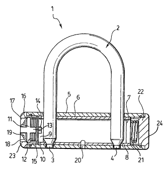
to Figure 1 one embodiment of a U-Lock is illustrated.
The U-lock, generally indicated at 1, consists of a U-
shaped shackle 2 designed to have its ends 3,4 inserted
within a cylindrical tube or lock body 5. The locking
mechanism includes within the lock body 5, an inner tube
6, that is adapted to be rotated by a key from a locking
to an unlocking position and back, to lock and unlock
shackle 2 within the lock body 5. The inner tube 6 has an
end plug 7 at one end 8 and a driven plug 9 at the other
end 10. A driver 11 is biased away from contact with the
driven plug 9 by compression spring 12 or other suitable
bias means. Driver 11 is equipped with a projecting shaft
13 sized and shaped to fit within a corresponding hole 14
on the face 15 of the driven plug 9. In Figure 1 both
projecting shaft 13 and the hole 14 on driven plug 9 have
a hex-shaped cross-section albeit other shapes are
possible. The face 16 of the driver 11 remote from shaft
CA 02622576 2008-03-14
WO 2007/030942
PCT/CA2006/001519
-4--
13 is provided with keyed access means that can be
engaged by a key to rotate driver 11. In the embodiment
shown the keyed access means includes a convex nut 17
that is attached to driver 11. The means of attachment in
Figure 1 is that nut 17 is threaded on and then riveted
to driver 9. A convex face 18 of nut 17 is preferably
provided with at least two cutouts 19 spaced away from
the axis of rotation of nut 17. The cutouts 19 are
located, sized and shaped for engagement by the mating
member on a specific key (not shown) for rotation of the
nut and driver about their axis. The cutouts 19 and key
are preferably of the type described in US Patent
6,341,927.
To operate the U-Lock of Figure 1, a combination key (not
shown) is inserted onto and into engagement with nut 17
so that projections on the key engage the cutouts 19 on
nut 17. As noted above nut 17 is fixed to one side of
driver 11. The driver 11 is floating in the lock body 5
by the weak compression spring 12. Unless the driver 11
is pushed in parallel with its axis, the shaft 13 on the
driver 11 cannot engage with the hole 14 in the driven
plug 9. The driven plug 9 is welded on the inner tube 6
so the inner tube 6 can be turned with the rotation of
the driven plug 9. On the inner tube 6 there are two "D"
holes to hold the shackle 2 and the shackle 2 goes
through to the opposite side. The inner tube 6 also
rotates limited angle and held in place by a lock pin 20.
The end plug 7 is welded on the other end of the inner
tube 6 and has a space for holding a torsion spring 21.
The torsion spring 21 is held between the end plug 7 and
an end cover 22.
Rotating the driven plug 9 can release the shackle 2. A
nut end cover 23 is provided around the nut 17. End cover
22 and nut end cover 23 are held in place by wire rings
24.
CA 02622576 2008-03-14
WO 2007/030942
PCT/CA2006/001519
- 5 -
In the embodiment of the U-Lock shown in Figure 1, co-
axial access to the nut 17 or other keyed access means is
unhindered. In the embodiment shown in Figure 1, nut 17
is recessed within nut end cover 22 to prevent access
from the side. To preclude unhindered co-axial access to
the nut 17 or other keyed access means, the present
invention, as shown in Figures 2 - 5, provides an outer
cylinder casing according to one embodiment of the
present invention enclosing keyed access means, in this
case the nut. By hiding the keyed access means to direct
access, the keyed access means cannot be engaged or
rotated other than with a matching coded key. While
Figures 2 to 5 only show the locking system with hidden
keyed access means of the present invention in
conjunction with a U-lock, the hidden keyed access means
can be used with other locking applications. For example
on a bicycle there may be locking skewers used to hold
the wheels and/or seat in place and/or locking head sets
to hold the handle bars in place and/or locking skewers
on vehicle racks. In accordance with the present
invention, one combination key can be provided to lock
and unlock the primary locking device (i.e. the U-lock)
retaining the bicycle to a fixed object such as a bike
rack and the other component secondary locking systems on
the bicycle (i.e. locking skewers, head set etc.).
In the embodiment shown in Figures 2-5, the present
invention features a keyed access means in the form of a
convex combination nut and a concave combination key
which match one another to provide positive engagement.
The convex combination nut is recessed and hidden from
view within a protective enclosure. To operate the lock,
the key must be first be inserted through a narrow slot
in the side of the protective enclosure. The key can then
be plunged towards the combination nut to create positive
engagement. The present invention is a significant
CA 02622576 2008-03-14
WO 2007/030942
PCT/CA2006/001519
- 6 -
improvement over the prior art by providing a locking
mechanism that is not accessible or visible and thus is
more difficult to pick or tamper with.
With reference to Figures 2-5 the U-lock 30 has a similar
construction to the U-lock shown in Figure 1. In Figures
2-5, a keyed access means in the form of a combination
nut 51 (number 17 in Figure 1) is housed within an outer
casing 52. The combination nut 51 is preferably of the
type described in US Patent 6,341,927. The operative
components of combination nut 51 are preferably at least
two cutouts provided on the face of the combination nut
51 and spaced away from the axis of rotation. The cutouts
are located, sized and shaped for engagement by the
mating member on a specific key for rotation of the nut
about its axis. Outer casing 52 has a cylindrical outer
wall 53 and end wall 54. Cylindrical outer wall 53 and
end wall 54 hide the operative components of combination
nut 51 from view and prevent the use of common tools to
engage and rotate the combination nut 51. A narrow slot
55 is provided within the cylindrical outer wall 53 and
end wall 54. The casing 52 can have any shape but in the
embodiment illustrated is cylindrical and sized to fit on
the end of the lock body of the U-lock. In other
applications the size and shape of the casing 52 may vary
to fit the application. The key 56 in the embodiment
shown (see Figures 3-5) has a body portion 57 with a
concave engaging surface 58 with projections 59 coded to
match the size, shape and location of the cutouts 60 on
combination nut 51. A shaft 61 extends from the surface
62 of body portion 57 opposite the concave engaging
surface 58. At the free end 63 of shaft 61 is a handle 64
pivotally mounted to shaft 61. The shaft 61 is sized to
fit in slot 55. The key 56 operates the lock by first
inserting it through slot 55 in the outer casing 52 and
then plunging it towards combination nut 51 to cause
active engagement with the combination nut 51.
CA 02622576 2008-03-14
WO 2007/030942
PCT/CA2006/001519
- 7 -
Figure 6 illustrates another locking application where
use of the same key as used on the primary locking system
i.e.U-Lock, can be used to lock a secondary component
locking system in the form of a bicycle head set. The
head set, generally indicated at 100, is used to hold the
handle bars to the bike. One end 101 of the head set 100
is equipped with a clamp member 102 which can be
tightened to the body 103 of head set 100 to hold the
handle bars (not shown) in the recess 104 defined between
the end 101 of head set 100 and clamp member 102. The
other end 105 of the body 103 of head set 100 is adapted
to connect the head set to the frame of the bicycle. A
top cap or casing 106 is provided around a vertical hole
107 in the end 105 of the body 103 of head set 100. Keyed
access means in the form of bolt 108, having a convex
head 109 and threaded shaft 110, is recessed within top
cap 106 with shaft 110 passing through the hole 107 and
threading into the bike frame (not shown) to hold the
head set in place. The convex head 109 of bolt 108 is
preferably of the type described in US Patent 6,341,927.
The operative components to permit rotation of bolt 108
are preferably at least two cutouts 118 provided on the
face of the convex head 109 and spaced away from the axis
of rotation of the bolt. The cutouts are located, sized
and shaped for engagement by the mating member on a
specific key for rotation of the nut about its axis as
described above for the U-Lock. The cutouts can use the
same combination as for the U-Lock described above and
therefore can use the same key. By recessing the head of
the bolt 108 it makes it difficult to access it with
common tools. A washer 111 is provided with a depending
and outwardly extending tab 112. Washer 111 ("POG
washer") is placed between the head of the bolt 108 and
the recess 113 in the top cap 106 with tab 112 fitting
into a slot 114 in top cap 106 and a second slot 115 in
the stem 116 at the end 105 of the head set 100. The tab
CA 02622576 2008-03-14
WO 2007/030942
PCT/CA2006/001519
-8-
112 on washer 111 prevents the top cap from being turned
in an effort to turn bolt 108. The side wall of top cap
106 can be extended and an end wall provided to result in
a hidden locking system similar to the one described in
Figures 2-5.
The head set of Figure 6 provides a compact, light-weight
headset locking system which is compatible with standard
bicycle designs. The head set of the present invention
overcomes problems with prior art through the use of a
convex-head combination bolt which can be rotated/torqued
only with the use of a matching key. The invention
features a slotted cap with a recessed center cavity.
When installed in its locked position, the combination
bolt convex head is recessed within the center cavity of
the slotted cap, thus preventing access by tools or other
pointed objects which could be used to pry or dislodge
the combination bolt. The slotted cap also prevents the
use of pin-style universal wrenches (known by the
tradename "Gator"-wrenches). The slotted perimeter of the
cap causes such pin wrenches to become engaged in the
cap, thus preventing their rotation of the combination
bolt. The invention also features a POG washer which
serves to prevent relative rotation between the slotted
cap and the bicycle headset stem. This prevents removal
of the lock by rotation of the slotted cap itself.
The slotted cap is inserted into the bicycle headset
stem. The POG washer is then inserted into the recessed
cavity of the slotted cap. The combination bolt is then
inserted and tightened into the bicycle headset stem to
prevent its removal from the bicycle frame. The center
cavity of the slotted cap provides a recessed protective
enclosure around the perimeter of the convex-head
combination bolt, thus preventing pointed objects such as
screwdrivers from gaining access to beneath the
combination bolt head. The POG washer features a
CA 02622576 2013-08-12
- 9 -
tangential leg which fits into the gap in the headset
stem and the slot of the slotted cap to prevent their
relative rotation. The combination bolt is threaded and
tightened into the headset stem to provide an effective
locking system which cannot be opened without the use of
a matching combination key.
Another example of a secondary component locking system
utilizing the same key as the U-lock and head set is
shown in Figure 7. A variation of the POG washer,
generally indicated at 120, with two upstanding
tangential tabs 121 or legs can be used as illustrated in
Figure 7 with other applications of the tamper resistant
fastener of the type described in US Patent No.
6,341,927. Figure 7 illustrates the use of the POG washer
120 with locking skewers (not shown) for the wheel of a
bicycle. The two upstanding tangential legs 121 or tabs
prevents the use of pin-style universal wrenches (known
by the tradename "Gator"-wrenches) from turning the
locking nut 122. The locking skewer on the bicycle wheel
would fit into the slot 123 on the bicycle frame 124. The
POG washer 120, together with conventional washer/spacers
125, 126 on either side of POG washer 120 slide over the
end of the locking skewer that would extend beyond the
bicycle frame 124. A depending flange 126 on POG washer
120 is adapted to fit in the slot 123 on the bicycle
frame the prevent the POG washer 120 from turning. A
tamper resistant locking nut 122 of the type described in
US Patent No. 6,341,927is then tightened on the threaded
end of the locking skewer.
In yet another embodiment of the invention, any shackle
having a free end can be used for locking a variety of
objects. Referring now to the drawings in detail, FIG. 8
illustrates a bicycle u-lock 240 comprising a shackle 210
releasably engaged on both ends in a lock housing 220.
CA 02622576 2008-03-14
WO 2007/030942
PCT/CA2006/001519
- 10 -
The ends 211), 212 of the shackle 210 have inward facing
grooves 211 which engage in the locked position with a
left stop 231) and right stop 232) as described more
fully below. When connected to the lock housing 220, the
shackle 210 is designed to lock a bicycle wheel and or
frame to a secure post, such as a standard bicycle rack.
The lock housing 220 has two sides, a shackle facing side
221 and a key facing side 222. The lock housing 220 is
illustrated in the embodiment shown as rectangular-shaped
but other shapes and size are within the scope of the
present invention. On the shackle facing side 221, there
are two cylindrical lock bodies 280, 281 as shown in FIG.
10, each of which receives a respective end 211, 212 of
the shackle 210, as best illustrated in FIG. 8.
As best illustrated in FIG. 10, the lock housing 220
includes an inner body 230, including, on its key facing
side 222 a keyed access means, shown generally at 224.
The inner body 230 is comprised of two links 233, 234
which are diametrically opposed to each other, each of
which have a stop link 231 232 on each opposite end 270,
271 and wrench faces 235 and 236 on each facing end 272,
273. The two links 233 and 234 are connected with each
other through their wrench faces 235 and 236, each of
which is connected to a tooth 237 and 239 for each face.
The teeth 237 and 239 are both mounted on a disc 239,
which can be seen in FIG. 8. The bottom side of the disc
238 is connected to a driveably connectable means, such
as a nut shaft 251, which houses a convex nut 250 at its
distal end 254. Nut 250 has a convex top face 255 and a
flat opposite surface 256. The nut 250 has at least one
cutout 252 on its convex face and houses a spring 253
within the cavity of the nut 250.
CA 02622576 2008-03-14
WO 2007/030942
PCT/CA2006/001519
- 11 -
With reference to FIG. 9, a key 300 is provided. The key
300 has a handle 310, a plug 330, and a t-shaped shaft
320 connecting the handle 310 to the plug 330. With
reference to the embodiment shown, a key 300 having only
a mating member 330 and some form of handle can also be
used, even where the shaft itself forms the handle. The
t-shaped shaft 320 pivots about pivot screw 340 which
connects the t-end of the shaft 320 to the handle 310,
thereby allowing flexibility in operating the key 300 and
locking system 340. The mating member 330 is concave-
shaped having at least one protruding pin 331 which
projects out of the concave face of the mating member 330
and is ready to be inserted into a cutout 352 having the
same size, space and location to ensure a secure
interaction.
To operate the bicycle u-lock 340 of FIG. 8, a key 300,
as shown in FIG 9, is inserted onto and into engagement
with the nut 350 through the keyed access means so that
the pin 331 interlocks with the cutout 352 and secures
the nut with the mating member 330. Once engaged, when
the key 300 turns left and has pressure applied in the
direction of the shackle facing side 321, the spring 353
is compressed from its resting and expanded state
simultaneously while the shaft 351 rotates about its
vertical axis, causing the disc 339 to rotate left along
its horizontal axis. The teeth 337 and 338 then pull
each respective wrench faces 335 and 336 and consequently
pull each link 333 and 334 towards each other. When the
links 333 and 334 are pulled toward each other, their
respective stop links 331 and 332 are also pulled inwards
and create an opening in the cylindrical lock bodies and
release the inward facing grooves 311 of a shackle 310.
Once the inward facing grooves 311 are released, the ends
of a shackle 310 are then free to slide out of the
CA 02622576 2013-08-12
- 12 -
aperture and into the open position. Conversely,
rotation of the key 300 to the right results in the stop
links 331 and 332 wedging into the inward facing grooves
311, securely locking the ends of the shackle 310 within
the lock housing 320 and into the closed/locking
position.
As shown in FIG. 8, the means to access the mating member
330 with a nut 350 is unhindered. Nut 350 is recessed
within nut end cover 360 to prevent direct access from
the key facing side 322. As such, nut 350 cannot be
engaged or rotated other than with a corresponding key
300 and is more difficult to tamper with than locks
disclosed in the prior art. In order to operate the
bicycle u-lock 340, the key 300 must be inserted sideways
through a narrow slot in the key facing side 322 of the
lock housing 320. Once inserted, the key 300 can then be
plunged towards the nut 350 to create a positive and
secure engagement.
To deter thieves from simply cutting through the shackle
310 and releasing the secured objects, the shackle 310 is
preferably constructed of a sturdy, corrosion-free
metallic material which cannot be readily broken, even
with the use of a crowbar and the like.
Although various preferred embodiments of the present
invention have been described herein in detail, it will
be appreciated by those skilled in the art, that
variations may be made thereto without departing from the
spirit of the invention. The scope of the claims should
not be limited by the preferred embodiments set forth in
the examples, but should be given the broadest
interpretation consistent with the description as a whole.