Note: Descriptions are shown in the official language in which they were submitted.
CA 02622731 2010-05-31
MEDICAL DEVICE WITH ARTICULATING SHAFT
Background Of The Invention
1 Field of the Invention
[002] The invention relates generally to surgical devices and methods,
and more particularly to shafts.
2. Description of Prior Art and Related Information
[003] In various types of surgical procedures, particularly in endoscopy, a
need exists for articulating, or bendable shafts. Such shafts are preferable,
and
often times necessary, for circumnavigating particular areas in the human body
in
order to reach a specific destination therein. Articulating shafts in the
prior art
include complex mechanisms that are expensive to manufacture and difficult to
-1-
CA 02622731 2008-02-22
WO 2007/146842 PCT/US2007/070810
assemble. These complexities have derived, at least in part, from the need to
provide tension in order to cause the shaft to bend.
[004] Such shafts in the prior art include flexible portions which can bend
in only one direction through the use of various types of tensioning
mechanisms.
Since the pathway to a particular desired location in a human body is often
circuitous in more intricate surgical procedures, bending a shaft in only one
direction can be very limiting. To overcome this deficiency, mechanisms to
rotate
a one-way bending shaft have been employed. Of course, having to manipulate
a knob to rotate a shaft and then having to pull a tension mechanism to bend a
shaft increases the complexity of a surgical procedure.
[005] Prior art articulating shafts also include those that bend in opposite
directions. Nonetheless, the bending of such shafts is accomplished by tension
which means that at least two tensioning mechanisms are provided: one to cause
the bend in a first direction, and the other to cause the bend in an opposite
direction. Use of these types of shafts requires the technician to select the
appropriate tensioning mechanism.
[006] Articulating shafts in the prior art are also highly complex. These
complexities have derived from the requirement of bending a distal portion of
a
shaft with a mechanism located at a proximal end of a medical device. Such
complexities relate to both the manufacturing and operation of these devices.
Prior art articulating shafts also lack rigidity. This is due at least in part
to the fact
that tensioning mechanisms in the prior art do not provide sufficient
rigidity.
-2-
CA 02622731 2008-02-22
WO 2007/146842 PCT/US2007/070810
Under standard use, prior art shafts are often unable to maintain a sufficient
articulated form or shape.
[007] No simple structure has been devised to accomplish ease of
operation and flexibility with a desired rigidity.
-3-
CA 02622731 2008-02-22
WO 2007/146842 PCT/US2007/070810
Summary Of The Invention
[008] In accordance with the present invention, structures and associated
methods are disclosed which address these needs and overcome the
deficiencies of the prior art.
[009] In one aspect, a medical device comprises a bendable portion, or
articulating shaft. The bendable portion is formed from a plurality of pivot
members that are arranged in succession and a related plurality of pivot
assemblies that pivotally connect adjacent ones of the plurality of pivot
members.
In one embodiment, bendable portion includes a plurality of independent pivot
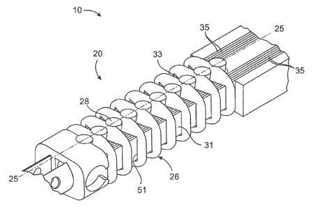
members and pins in an alternating configuration. In another embodiment, the
bendable portion includes a plurality of overlapping members that are
provided,
for example, as inner links and outer links. The outer links define an
aperture
adapted to have the inner links substantially extended therethrough. A first
slat
assembly and second slat assembly extend through the bendable portion. Each
of the first slat assembly and the second slat assembly is configured to push
when the other of the first slat assembly and the second slat assembly pulls
so
as to cause the bending portion to bend.
[010] In an embodiment involving separate pivot members, the openings
collectively define an outer passageway while the pin apertures collectively
define an inner passageway. The first slat assembly extends through the outer
passageway alongside a first side of the pins while the second slat assembly
extends through the outer passageway alongside a second side of the pins
-4-
CA 02622731 2008-02-22
WO 2007/146842 PCT/US2007/070810
opposite the first side of the pins. The inner passageway provides a path for
an
actuator, a flexible tube, electrical wiring and/or light transmitting media,
such as
optical fibers, to extend through the bendable portion. The actuator may be
formed with a variety of cross-sectional shapes, such as a rectangle, square,
circle, etc.
[011] In an embodiment involving overlapping pivot members, each of the
inner links comprises a male tab and a female slot, and defines a first
aperture
and a second aperture, and each of the outer links comprises a male tab and a
female slot. The first slat assembly extends through the first aperture of the
inner
links and the aperture of the outer links, and the second slat assembly
extends
through the second aperture of the inner links and the aperture of the outer
links.
[012] In an alternative embodiment, each of the outer links defines an
aperture, and each of the inner links defines an aperture adapted to form a
common channel with the aperture of each of the outer links. The inner links
and
outer links are connected with half pins. A gap between paired half pins
defines
an inner passageway. Alternatively, the inner links and outer links are
connected
with pins having a pin aperture, and the pin aperture defines an inner
passageway.
[013] An articulator is coupled to the first slat assembly and the second
slat assembly such that operation of the articulator causes one of the first
and
second slat assemblies to push and the other of the first and second slat
assemblies to pull simultaneously. In an embodiment, movement of the
articulator in one direction causes the bendable portion to bend in an
opposite
-5-
CA 02622731 2008-02-22
WO 2007/146842 PCT/US2007/070810
direction away from the direction of movement of the articulator.
Alternatively,
intermediate mechanisms may be coupled to the slat assemblies and the
articulator to reverse this motion such that movement of the articulator in
one
direction causes the bendable portion to bend toward the same direction. Each
pivot member defines a vertical axis. The device may comprise means for
preventing each pin from moving vertically with respect to an adjacent pivot
member. Each pivot member preferably has a laterally tapered thickness.
[014] The first slat assembly comprises at least one slat and preferably a
first plurality of layered slats. The second slat assembly comprises at least
one
slat and preferably a second plurality of layered slats. The device further
comprises a rigid shaft portion coupled proximally to the bendable portion.
The
bendable portion may comprise a preconfigured and permanent curve that is
disposed, or bent, in a direction generally perpendicular to the range of
motion of
the bendable portion. For example, the preconfigured curve may be bent upward
or downward with respect to the rigid shaft portion.
[015] In another aspect, a medical device comprises a bendable portion
including a series of pivot members and pins in an alternating configuration.
A
first slat assembly is coupled to the bendable portion. A second slat assembly
coupled to the bendable portion. The pivot members may also include inner
links
and outer links. The outer links define an aperture adapted to have the inner
links substantially extended therethrough. Each of the first slat assembly and
the
second slat assembly is configured to push when the other of the first slat
-6-
CA 02622731 2008-02-22
WO 2007/146842 PCT/US2007/070810
assembly and the second slat assembly pulls so as to cause the bendable
portion to bend.
[016] The inner links and outer links are connected with pins. Each pivot
member may also comprise a male tab and a female slot, a male tab engaging a
neighboring female slot of a similar link. In an alternative embodiment, each
of
the outer links defines an aperture, and each of the inner links defines an
aperture adapted to form a common channel or passageway with the aperture of
each of the outer links. The inner links and the outer links are connected
with
half pins or with pins having an aperture.
[017] In a further aspect, a method is provided for articulating a shaft of a
medical device. The method comprises providing pivot members each having a
single opening, extending a first slat assembly through the single opening of
each pivot member, extending a second slat assembly through the single
opening of each pivot member, pushing one of the first and second slat
assemblies while concurrently pulling the other of the first and second slat
assemblies to cause the pivot members to collectively form a bend.
[018] The method further comprises providing an alternating plurality of
inner link pivot members and outer link pivot members, each pivot member
having an opening to collectively form a passageway, connecting adjacent ones
of the pivot members to one another with a pin, extending a first slat
assembly
through the passageway formed by the pivot members, extending a second slat
assembly through the passageway formed by the pivot members; and pushing
one of the first and second slat assemblies while concurrently pulling the
other of
-7-
CA 02622731 2008-02-22
WO 2007/146842 PCT/US2007/070810
the first and second slat assemblies to cause the pivot members to
collectively
form a bend.
[019] The method further comprises engaging a female slot of an inner
link pivot member with a male tab of a neighboring inner link pivot member,
and
engaging a female slot of an outer link pivot member with a male tab of a
neighboring outer link pivot member.
[020] The step of pushing one of the first and second slat assemblies
while concurrently pulling the other of the first and second slat assemblies
comprises moving an articulator. The step of moving the articulator comprises
moving the articulator to a left direction to cause the pivot members to
collectively
form a bend in a first direction, and moving the articulator to the right
direction to
cause the pivot members to collectively form a bend in a second direction.
[021] The method further comprises actuating an end operating, or tool,
assembly coupled distally to the articulating shaft.
[022] In summary, a medical device includes an articulating shaft with a
pair of slat assemblies. By moving an articulator, the slat assemblies are
configured to concurrently push while the other pulls in order to bend the
articulating shaft. The articulating shaft includes a series of pivot members
formed, for example, from alternating pins and pivot members, or from inner
links
and outer links. The slat assemblies extend generally parallel to each other.
A
method for articulating a shaft of a medical device is also provided.
-8-
CA 02622731 2008-02-22
WO 2007/146842 PCT/US2007/070810
[023] The invention, now having been briefly summarized, may be better
visualized by turning to the following drawings wherein like elements are
referenced by like numerals.
-9-
CA 02622731 2008-02-22
WO 2007/146842 PCT/US2007/070810
Brief Description Of The Drawings
[024] FIG. 1 is a perspective view of a first embodiment of an articulating
shaft according to the invention;
[025] FIG. 2 is a side elevation view of a medical device according to the
invention;
[026] FIG. 3 is a close-up perspective view of a portion of the first
embodiment of the articulating shaft;
[027] FIG. 4A is a close-up perspective view of a first pivot member of the
articulating shaft;
[028] FIG. 4B is a close-up perspective view of a second pivot member of
the articulating shaft;
[029] FIG. 5 is a perspective view of a pin;
[030] FIG. 6 is front elevation view of a pivot member and the pin;
[031] FIG. 7 is a perspective view an alternate pin;
[032] FIG. 8A is a perspective view of a medical device, illustrating the
articulating shaft and a rectangular actuator;
[033] FIG. 8B is a perspective view of a further medical device with a
cylindrical actuator;
[034] FIG. 8C is a perspective view of further embodiments having
electrical wires and/or optical fibers extending through the articulating
shaft and a
variety of operating mechanisms;
[035] FIG. 9 is perspective view of a further medical device, illustrating
the articulating shaft and a tube;
-10-
CA 02622731 2008-02-22
WO 2007/146842 PCT/US2007/070810
[036] FIG. 10 is a top plan view of the medical device showing the first
articulating shaft in a rest state;
[037] FIG. 11 is a top plan view of the medical device in FIG. 11 showing
the articulating shaft bent;
[038] FIG. 12 is a top plan view of an alternative embodiment where the
articulating shaft bends in the same direction in which the articulator is
moved;
[039] FIG. 13 is a top plan view of a further alternative embodiment
where the articulating shaft bends in the same direction in which the
articulator is
moved;
[040] FIG. 14 is a perspective view of an alternate embodiment of an
articulating shaft;
[041 ] FIG. 15 is a perspective view of an alternate pivot member of the
articulating shaft in FIG. 14;
[042] FIG. 16 is a side elevation view of a further alternate embodiment
of an articulating shaft;
[043] Figures 17 through 22 illustrate a further embodiment of an
articulating shaft, wherein,
[044] FIG. 17 is a perspective view of an articulated assembly of inner
and outer links in accordance with an embodiment of the invention;
[045] FIG. 18 is a perspective of an alternative embodiment of the inner
link;
[046] FIG. 19 is another perspective of the inner link shown in FIG. 18;
-11 -
CA 02622731 2008-02-22
WO 2007/146842 PCT/US2007/070810
[047] FIG. 20 is a perspective view of a half pin used to connect an inner
link with an outer link;
[048] FIG. 21 is a close-up perspective view of an inner link connected to
an outer link; and
[049] FIG. 22 is another close-up perspective view of the
connected inner link and outer link shown in FIG. 21;
[050] Figures 23 and 24 illustrate a modification to the
embodiment of Figures 17 to 22, wherein,
[051] FIG. 23 is a perspective view of a pin with a pin aperture used in
place of a pair of half pins; and
[052] FIG. 24 is a perspective view of an inner link and an outer link
connected using the pin shown in FIG. 23;
[053] Figures 25 to 34 illustrate an even further embodiment of an
articulating shaft, wherein,
[054] FIG. 25 is a perspective view of an articulated assembly of inner
and outer links;
[055] FIG. 26 is a perspective view of an inner link pivot member in
accordance with an embodiment of the invention;
[056] FIG. 27 is a different view of the inner link pivot member shown in
FIG. 26;
[057] FIG. 28 is a perspective view of an outer link pivot member in
accordance with an embodiment of the invention;
-12-
CA 02622731 2008-02-22
WO 2007/146842 PCT/US2007/070810
[058] FIG. 29 is a different view of the outer link pivot member shown in
FIG. 28;
[059] FIG. 30 is a perspective view of a pin used to attach pivot
members;
[060] FIG. 31 is a perspective view of a portion of the shaft including
connected inner and outer links in accordance with an embodiment of the
invention;
[061] FIG. 32 is a close-up perspective view of engaged inner links of a
portion of the shaft;
[062] FIG. 33 is a close-up perspective view of connected inner link and
outer link of a portion of the shaft; and
[063] FIG. 34 is an illustration of constrained relative movement between
the inner links and the outer links;
[064] The invention and its various embodiments can now be better
understood by turning to the following detailed description wherein
illustrated
embodiments are described. It is to be expressly understood that the
illustrated
embodiments are set forth as examples and not by way of limitations on the
invention as ultimately defined in the claims.
-13-
CA 02622731 2008-02-22
WO 2007/146842 PCT/US2007/070810
Detailed Description of the Preferred Embodiments and
Best Mode of Invention
[065] The herein invention may be embodied various medical devices
that include an articulating or bendable portion formed from a plurality of
pivot
members that are arranged in succession and a related plurality of pivot
assembly that pivotally connect adjacent ones of the plurality of pivot
members.
[066] A first embodiment of a medical device is illustrated in Figures 1
and 2 and designated generally by the reference numeral 10. The medical
device, or instrument, 10 is particularly configured for intricate surgical
procedures where a direct, straight path to a desired destination is
unavailable.
In particular, endoscopic surgeries typically require circumnavigation around
particular areas within the human body in order to reach a desired location
for
treatment.
[067] The device 10 includes an articulating shaft, or bendable portion,
20 of particular interest to the invention. The articulating shaft 20 is
formed as a
distal portion of an overall shaft 22 that also includes a proximal rigid
shaft
portion 24. The overall shaft 22 defines a longitudinal axis 25. In the first
embodiment, the articulating shaft 20 comprises a plurality of independent
pivot
members 26 and pins 28 disposed in an alternating configuration. Thus, each
pin 28 abuts an adjacent, but separate pivot member 26 in a rotatable, or
pivotable, relationship as described in further detail below.
-14-
CA 02622731 2008-02-22
WO 2007/146842 PCT/US2007/070810
[068] The device 10 comprises a first slat assembly 31 and a second slat
assembly 33. Each slat assembly 31, 33 comprises at least one flat, elongate
slat 35 that is generally elongate, flat and thin. The slats 35 are preferably
composed of a super elastic material such as Nitinol. In the embodiment, each
slat assembly 31, 33 comprises a plurality of slats 35 disposed, or layered,
side-
by-side. Alternatively, the slat assemblies 31, 33 may include layers of other
material, such as TEFLON , disposed in between the slats 35. The slats are
preferably disposed in a vertical orientation with respect to the shaft 20 so
as to
restrict the pivot members 26 from vertical movement. Except for the bending
accomplished by the axial movement of the slat assemblies 31, 33 as described
below, the slat assemblies 31, 33 also restrict individual sideways movement
of
any particular pivot member 26 and pin 28. In Figure 2, the slat assemblies
31,
33 are ultimately coupled to an articulating mechanism, or articulator, 37
provided at a proximal end 39 of the device 10.
[069] In Figure 2, an operating mechanism 42 is coupled to the
articulating shaft 20 generally at a distal end 44 of the device 10. In the
illustrated embodiment shown in Figure 2, the operating mechanism 42 is shown
as forceps with a pair of jaws. It is to be expressly understood, however,
that the
device 10 may comprise a variety of operating mechanisms and tools at the
distal end 44. As examples and not by way of limitation, the device 10 may
comprise graspers, clips, suturing mechanisms, cutters, shavers, retractors,
water jet cutters, RF ablation devices, imaging and/or light transmitting
fibers
(e.g., lasers, optical fibers, etc.) and a host of other mechanisms coupled to
a
-15-
CA 02622731 2008-02-22
WO 2007/146842 PCT/US2007/070810
distal end of the articulating shaft 20 according to the invention. Where
actuation
of a particular operating mechanism is necessary, the device 10 may comprise a
proximal handle assembly 46 which includes a pair of handles 48, one of which
is
coupled to an actuator (hidden) extending through the overall shaft 22.
[070] Figure 3 is a close-up view of a portion of the articulating shaft 20,
particularly an alternating combination of pivot members 26 and pins 28
illustrated in a bent configuration. As shown in Figures 3 and 4A, each pivot
member 26 comprises a single opening, or through hole, 51. The pivot member
openings 51 may be formed in a variety of shapes and sizes. In the
embodiment, the openings 51 are shaped generally rectangular. Where the
openings 51 are rectangular as shown, each pivot member 26 may include
rounded, or radiused, corners 53 to minimize stresses in the corners 53 and to
provide sufficient clearance for slat assemblies. Each pivot member 26
includes
a top portion 55 and a bottom portion 57 joined by side portions 59. The top
portion 55 and bottom portion 57 have substantially similar structures. In
particular, each of the top portion 55 and bottom portion 57 includes a pair
of
opposite curved recesses 62 for receiving pins 28, as shown in Figure 3. The
recesses 62 are smoothly curved to facilitate easy pivoting, or rotation,
between
each pin 28 and an adjacent pivot member 26. To better facilitate a bend in
the
articulating shaft, each pivot member 26 preferably has a laterally tapered
thickness. In particular, the thickness of each pivot member 26 decreases from
a
medial portion of the pivot member 26 to the lateral, or side, portions 59.
Each
pivot member 26 defines a vertical axis 63 as shown in Figure 4.
-16-
CA 02622731 2008-02-22
WO 2007/146842 PCT/US2007/070810
[071] In Figure 4A, the opening 51 of the pivot member 26 is shown as
generally rectangular. As discussed further below, the articulating shaft 20
may
be configured to receive slat assemblies in combination with a variety of
other
structures with differing sizes, such as an actuator, a tube, electrical
wiring, and
more. Accordingly, a further embodiment of pivot member 26b is provided and
illustrated in FIG. 4B having an opening 51 b with a taller central section 60
for
accommodating a larger structure extending therethrough.
[072] In Figures 3 and 5, the pin 28 comprises a pin aperture, or through
hole, 64 that is also defined by rounded, or radiused, corners 66 to minimize
stresses in the corners 66 and to provide sufficient clearance for actuators,
conduits or whatever mechanism may be inserted therethrough. As described
further below, the pin apertures 64 collectively define an inner passageway,
or
path, for receiving an actuator, a tube, electrical wiring, or light
transmitting media
such as optical fibers. Each pin 28 comprises a central portion 68 with an
increased diameter than that of the top portion 71 and bottom portion 73 so as
to
form top and bottom shoulders 75. As shown in Figures 3 and 6, the pin
shoulders 75 restrict vertical movement between the pin 28 and an adjacent
pivot
member 26 by abutting the inner surfaces of the top portion 55 and bottom
portion 57 of the pivot member 26. Also in Figures 3 and 6, the mating of the
pin
top portion 71 and the pin bottom portion 73 with the curved recesses 62 of
the
pivot members 26 centers each pin 28 with respect to an adjacent pivot member
26 while enabling free pivoting therebetween. In Figures 1 and 6, the openings
51 of the pivot members 26 collectively form an outer passageway through which
-17-
CA 02622731 2008-02-22
WO 2007/146842 PCT/US2007/070810
the slat assemblies 31, 33 are inserted. As shown in Figure 6, it will be
appreciated that the embodiment of the device obviates the need for multiple
lumens, or bores. By forming the pivot member 26 as a generally rectangular
frame with a dominant opening 51, multiple slat assemblies may extend the
pivot
members 26 without need for aligning any lumens.
[073] In an alternative embodiment shown in Figure 7, the pin 28b may
simply comprise a substantially cylindrical outer surface 77 and a pin
aperture
64b.
[074] Figure 8A is a perspective view of a partially assembled device 10,
shown with slat assemblies 31, 33 and an actuator 80 configured for
reciprocating, or oscillating, movement along the axis of the shaft as
indicated by
the bi-directional arrows. In the illustrated embodiment, the actuator 80 has
a
rectangular cross-sectional profile with a height greater than its width such
that,
when it is in a straight configuration, the actuator 80 substantially defines
a plane
P. Accordingly, the actuator 80 with a rectangular profile thus has a greater
elasticity, or flexibility, normal to the plane P than in the plane P.
Alternatively
stated, the actuator 80 can be easily bent in accordance with the range of
motion
of the articulating shaft, but not perpendicularly with respect to such range
of
motion. The actuator 80 is inserted through the pin apertures 64 so as to
extend
through the articulating shaft 20. The first slat assembly 31 and second slat
assembly 33 are inserted through the openings 51 in the pivot members 26. The
first slat assembly 31 and second slat assembly 33 extend through the
articulating shaft 20 on opposite sides of the pins 28 and the centrally
located
-18-
CA 02622731 2008-02-22
WO 2007/146842 PCT/US2007/070810
actuator 80. A connecting mechanism 82 is provided at distal end of each slat
assembly 31, 33. In the illustrated embodiment shown in Figure 8A, the
connecting mechanism 82 may comprise transverse slots 84 for receiving bars
(not shown). The connecting mechanism 82 may also comprise particularly
shaped keys 86 formed at the distal end of the slat assemblies 31, 33 and
configured to fit into a slot 88 of a distal tip 90 of the articulating shaft.
[075] In Figure 8B, the device 10 may comprise a cylindrical actuator 80b
such that, in addition to a reciprocating motion, it can be rotated to
transfer a
torsional force from a proximal end of the device 10 to the distal end.
[076] In further embodiments illustrated in Figure 8C, the device 10 may
comprise electrical wiring or optical fibers, both designated by the numeral
91,
instead of an actuator extending through the pin apertures 64. The electrical
wires or optical fibers 91 may then be coupled to a variety of different
operating
mechanisms formed at a distal end 44 depending upon the desired application.
For example, electrical wiring 91 may be coupled to an electrically activated
device, such an RF ablation device 92-1 or an electrically passive device,
such
as a thermal couple, indicated conceptually by numeral 92-2. As a further
example, optical wiring 91 may be provided and coupled to a fiber optic device
92-3, or simply terminated at the distal end 44.
[077] In place of an actuator, the device 10 as shown in Figure 9 may
comprise a tube, or conduit, 93 for providing a pathway or passage for fluids,
needles or any other materials of interest that need to be delivered to a
desired
site. Thus, the articulating shaft 20 according to the invention may be
-19-
CA 02622731 2008-02-22
WO 2007/146842 PCT/US2007/070810
incorporated into a medical device 10 in order to transport or deliver
liquids,
materials and/or other medical devices to areas within the human body that do
not offer a direct pathway.
[078] Figures 10 and 11 are top operative views of the first embodiment
of the device 10. In Figure 10, the device 10 is shown in a rest, or default,
state
wherein the articulating shaft 20 and articulator 37 are both straight and,
thus,
aligned substantially along the axis 25 defined by the rigid proximal shaft
portion
24. The articulator 37, and thus the articulating shaft 20, is preferably
biased to
this straight position, although the device 10 may be formed such that the
articulator 37 and articulating shaft 20 are biased to a non-straight, off-
axis
position.
[079] In Figure 11, the bending, or articulating, of the articulating shaft 20
is illustrated. In particular, the articulator 37 may be bent in a first
direction
indicated by arrow 94a, thereby causing the articulating shaft 20 to also bend
in
an opposite direction 94b. When a user moves the articulator 37 in the first
direction 94a, the first slat assembly 31 is pulled, or tensioned, while the
second
slat assembly 33 is concurrently pushed, or compressed. Unlike certain
articulating shafts in the prior art which operate solely by tension, the
device 10
according to the invention operates by employing both push and pull forces
simultaneously. It will also be appreciated that the dual opposing forces are
caused by a single movement of the articulator 37.
[080] In a similar manner, the articulator 37 may be bent in a second
direction as shown by phantom lines and indicated by arrow 96a, thereby
-20-
CA 02622731 2008-02-22
WO 2007/146842 PCT/US2007/070810
causing the articulating shaft 20 to also bend in an opposite direction 96b as
a
result of the first slat assembly 31 being pushed while the second slat
assembly
33 is concurrently pulled.
[081] An appreciable advantage of the device 10 is that the articulator 37
is intentionally located for convenient operation by a user. Though it is to
be
expressly understood that there a variety of ways to move the articulator 37,
one
appreciable advantage of the device 10 is that the articulator 37 can be moved
by the thumb of the same hand holding the handle assembly. Thus, in the
embodiment, the articulator 37 is disposed adjacent to and above the handles
48
as shown in Figure 2. By positioning the articulator 37 in this highly
desirable
location, it will be appreciated that, where an actuator is employed, the user
may
both articulate the shaft 20 and actuate the device 10, all with one hand.
Though
the user may choose to use the other hand to move the articulator 37, it is
not
required. Instead, the user can simply leave his or her thumb on the
articulator
37 at all times to move the articulating shaft 20 to the right or left as
desired.
[082] In embodiments disclosed herein, it will be appreciated that the
dual slat assemblies 31, 33 provide sufficient rigidity to the articulating
shaft 20.
In particular, the dual slat assemblies 31, 33 rigidly maintain the
articulating shaft
20 in its straight or bent form without deflection. Though each slat assembly
31,
33 may comprise a single slat, the rigidity of the articulating shaft 20 is
enhanced
by each slat assembly 31, 33 comprising a plurality of layered slats.
Furthermore, by orienting the slats in the vertical direction, the slat
assemblies
-21 -
CA 02622731 2008-02-22
WO 2007/146842 PCT/US2007/070810
31, 33 not only rigidly hold the shape of a bent articulating shaft 20, but
also
prevent any vertical deflection of the articulating shaft 20.
[083] In this embodiment, the articulating shaft 20 is configured to bend in
a direction opposite to the manipulated direction of articulator 37. For
example,
from the vantage point of the user (i.e., looking at the device 10 from the
rear),
when the articulator 37 is bent to the right, indicated by arrow 94a in Figure
11,
the articulating shaft 20 bends to the left as indicated by arrow 94b in
Figure 11.
The device 10 may be configured to reverse the bending motion shown in Figure
11, such that the articulating shaft 20 bends in the same direction as the
articulator 37. Thus, different mechanisms may be employed to reverse the
directions of the pushing and pulling forces caused by movement of the
articulator 37. In Figure 12, for example, a set of gears 97 may be provided
at
the proximal end of the slat assemblies 31, 33 and coupled to the articulator
37.
A variety of intermediate links and coupling mechanisms may be employed to
couple the slat assemblies 31, 33 to the gears 97. In the embodiment shown in
Figure 12, moving the articulator 37 in a first direction 94a now causes the
articulating shaft 20 in bend in the same direction 94b. In particular, moving
the
articulator to the right 94a will push the first slat assembly 31 and
simultaneously
pull the second slat assembly 33. Accordingly, moving the articulator 37 in
the
second direction 96a will cause the articulating shaft 20 to also bend in a
similar
direction 96b. It should also be appreciated that the articulating shaft 20
may be
configured to bend to a greater or lesser degree. In the illustrated
embodiment in
Figure 12, the articulating shaft 20 is illustrated with a bend greater than
90 from
-22-
CA 02622731 2008-02-22
WO 2007/146842 PCT/US2007/070810
the axis 25 such that the distal end 44 of the device 10 is now pointing in a
proximal direction toward the proximal end 39 of the device 10.
[084] In a further alternative embodiment shown in Figure 13, this "same-
side" bending may also be accomplished without gears by criss-crossing the
slat
assemblies 31, 33. Moving the articulator 37 in a first direction 94a pushes
the
first slat assembly 31 and pulls the second slat assembly 33 such that the
articulating shaft 20 also bends in a similar direction 94b as the articulator
37.
Accordingly, moving the articulator in the second direction 96a will cause the
articulating shaft 20 to also bend in a similar direction 96b. To enable the
slat
assemblies 31, 33 to criss-cross, the slat assemblies 31, 33 may be disposed
on
different planes, for example, or provided with slots to enable one assembly
to
intersect the other. It will be appreciated that a variety of mechanism may be
used to accomplish the criss-crossing between the slat assemblies 31, 33.
[085] Figure 14 is a perspective view of an alternative embodiment of a
device 10c including an alternative articulating shaft 20c where elements of
similar structure are designated by the same reference numerals followed by
the
lower case "c". In Figure 14, the device 10c includes a first slat assembly 31
c
and a second slat assembly 33c, each having an elongate slot 102. The shaft
20c includes a series of alternating pivot members 26c and pins 28c. In Figure
15, each pivot member 26c includes an opening 51 c, and a pair of oppositely
extending arms 104. Each arm 104 includes a neck 106 and a lateral tab 108.
When assembled, the arms 104 of the pivot members 26c extend laterally
through the elongate slots 102 of the slat assemblies 31c, 33c as shown in
-23-
CA 02622731 2008-02-22
WO 2007/146842 PCT/US2007/070810
Figure 14. The lateral tabs 108 secure the pivot members 26c to the slat
assemblies 31 c, 33c. The device 10c may also include a sheath 110, shown
partially here, over the articulating shaft 20c. It is to be understood that
the
sheath 110 may be provided in all of the previously disclosed embodiments.
[086] Figure 16 is a side elevation view of a further alternative
embodiment of a device 10d having a permanent, preconfigured curve. In this
embodiment, elements of similar structure are designated by the same reference
numerals followed by the lower case "d". In the illustrated embodiment, the
articulating shaft 20d is permanently curved to an angle B in a direction that
is
generally perpendicular to the two-way bending (i.e., range of motion) of the
articulating shaft 20d. Alternatively stated, the articulating shaft 20d is
preferably
configured to bend to the right and left directions, which directions
collectively
define the range of motion of the articulating shaft 20d. The articulating
shaft 20d
thus comprises a permanent, preconfigured curve that is perpendicular to this
range of motion. The articulating shaft 20d includes pivot members 26d and
pins 28d substantially similar in structure to the first embodiment described
above in connection with Figures 1-11 except that the pivot members 26d and
pins 28d may have tapered top portions to better facilitate the permanent
upward
curve. Here, the permanent curve is in an upward direction while the
articulating
shaft 20d is bendable to the right and left directions. Accordingly, the slat
assemblies 31d, 33d comprise slats formed with permanent curves that conform
to the permanent curve of the articulating shaft 20d. The device 10d also
includes an actuator 80d that is bent in conformity with the permanent curve
of
-24-
CA 02622731 2008-02-22
WO 2007/146842 PCT/US2007/070810
the shaft 20b. It is to be expressly understood that the articulating shaft
20d may
be formed with a permanent curve in any direction off the axis 25d of the
rigid
proximal shaft portion 24d. Accordingly, where a permanent downward curve is
formed in the articulating shaft, the pivot members 26d and 28d may be formed
with tapered lower portions.
[087] Alternatively described, the device 10d in Figure 16 includes a rigid
shaft portion 24d with a top surface 112 that defines a plane C. The
articulating
shaft 20d includes a permanent curve that is bent in a direction away from the
plane C. Here, the permanent curve of the articulating shaft 20d is shown as
being perpendicular to the plane C, namely, upward.
[088] In each of the foregoing embodiments, the articulating shaft is
formed from independent pivot members and a plurality of pins disposed in an
alternating configuration. But, in accordance with further embodiments of the
invention, the articulating shaft may be formed from interconnected pivot
members or links. The following description of several such embodiments
generally uses like figures for like elements.
[089] Figures 17 through 22 illustrate an embodiment where an
articulating shaft 20e is formed from a succession of interconnected pivot
members comprised of inner links 126e and outer links 226e. Here, the inner
and outer links 126e, 226e are connected to one another by half pins 28e. As
explained more fully below, one or more working channels are formed along the
length of this articulating shaft 20e to allow items, such as articulating
slats,
actuators, torque mechanisms, etc., to pass there along, as described earlier.
-25-
CA 02622731 2008-02-22
WO 2007/146842 PCT/US2007/070810
[090] Figure 18 is a perspective view of one inner link 126e. As shown,
the inner link 126e comprises two plates 250 with two pin holes 257, and two
side walls 258. The two plates 250 and two side walls 258 form an aperture or
through space 259.
[091] Figure 19 is a perspective view of one outer line 226e. As shown,
the outer link 26h also has two plates 264 with two pin holes 263, and two
side
walls 262. The two plates 264 and the two side walls 262 also form an aperture
or through space 265.
[092] A half pin 28e, as shown in Figure 20, is roughly a cylindrical solid
and is used to connect the outer link 226e with the inner link 126e. Many
variations of the half pin 28e may be recognizable to those skilled in the
art. For
example, the ends 277 do not need to be parallel and/or flat. A variation of
the
half pin 28e includes having a shoulder on one or both ends that can be larger
or
smaller than the pin diameter. This can aid in fixation and/or manufacturing.
[093] As shown Figure 21, an inner link 126e is attached to an outer link
226e with two half pins 28e. After the inner link 126e is slid inside the
outer link
226e, the half pins 28e are slid into the aligned outer link pin hole 263 and
the
corresponding inner link pin hole 257. The half pins can be held in place with
a
variety of methods such as press fitting, gluing using adhesive, laser
welding,
etc. The half pin 28e is free to rotate relative to at least one of the holes
such
that the inner link 126e can rotate relative to the outer link 226e.
[094] Figure 22 is another view of the same assembly shown in Figure
21. In this view, it is apparent how the two sets of side walls (258 and 262)
and
-26-
CA 02622731 2008-02-22
WO 2007/146842 PCT/US2007/070810
two sets of plates (250 and 264) combine to create a long working channel 299,
which can be utilized in a variety of ways as described earlier. Another
channel
295 is formed between gaps of paired half pins 28e, which as shown is a part
of
the working channel 299, and may be considered an "inner" passageway.
[095] Figures 23 and 24 show a further embodiment relative to that of
Figures 17 to 22. Here, in place of the half pin 28e, a slotted pin 28e' is
used
which, as shown in Figure 33, is longer and contains a pin slot or aperture
311.
In the assembly, this pin goes through two sets of pin holes 257 and 263 of
the
links such that it bridges the gap between the two sets of plates 250 and 264.
The pin can be attached to none, one or both sides but must not be connected
to
both plates on one side (e.g. 250 and 264 on Figure 22) because that would
restrict relative rotational movement of the outer link 226e to the inner link
126e
is restricted. The pin slot or aperture 311 acts as a continuation of, and
helps
define or maintain the links' working channels 299 and 295 (see Figure 22).
[096] An assembly with this pin 28e' is shown in Figure 24. The
assembly is similar to that of Figure 22 except the two half pins 28e are
replaced
by one slotted pin 28e'. The pin slot or aperture 311 now defines the inner
passageway in place of the gap between two half pins.
[097] Figures 25 through 34 illustrate another embodiment where an
articulating shaft 20f is also formed from a succession of interconnected
pivot
members comprised of inner links 126f and outer links 226f.
[098] However, as shown in Figure 25, the inner and outer links 126f,
226f of the articulating shaft 20f are connected links of opposite type by
full-
-27-
CA 02622731 2008-02-22
WO 2007/146842 PCT/US2007/070810
height pins 28f. Moreover, as more fully described below, the inner links 126f
and outer links 226f are connected to adjacent links of similar type by male
locking tabs and female locking slots. Two slat holes 176a and 176b extend
along the length of the assembly.
[099] Figures 26 and 27 are perspective views of one inner link 126f. As
shown, an inner link 126f comprises a male locking tab 171 and a female
locking
slot 172. The female locking slot 172 may be formed, for example, with two
extrusions 184.
[100] The inner link 126f has two pin holes 173 and 174 extending
therethrough. A side wall 175 and an outer surface 177 of the main body of the
inner link 126f define a first aperture 176a, which is adapted to have a first
slat
extended therethrough. A second aperture is also defined, as a second slat
hole
176b, on the other side of the inner link 126f. Figure 27 provides a
perspective
view of the inner link 126f from the direction of the female locking slot 172.
[101] Figures 28 and 29 are different perspective views of one outer link
226f. The outer link 226f also has male locking tabs 291 and female locking
slots 292, and four pin holes 293. The side walls 294 connect the top and
bottom
portions of the outer link 226f, and will act as a constraint for the slats
once
assembled. The side walls 294 and the top and bottom portions of the outer
link
226f form an aperture 290. The aperture 290 is sufficiently large for the
inner link
126f to slide in.
[102] Figure 30 shows the pin 28f used to connect the links during
assembly. The pin 28f does not need to have an aperture.
-28-
CA 02622731 2008-02-22
WO 2007/146842 PCT/US2007/070810
[103] Figure 31 is a partial assembly of two outer links 226f connected to
an inner link 126f. The male locking tab 291 of one outer link 226f is placed
in
the female locking slot 292 of another, neighboring outer link 226f. The same
tab
lock assembly pertains to the Inner links 126f, where the male tab 171 one
inner
link 126f is placed in the female slot 172 of an adjacent inner link 126f as
shown
in Figure 32.
[104] It is recognizable to those skilled in the art that for both the outer
links and the inner links, there are many variations in the male/female design
combinations that may be implemented.
[105] A series of inner links are placed within a series of outer links
through the outer link aperture 290, and neighboring links (inner to outer)
are
pivotally connected with pins 28f. The design of the male tabs (171 and 291)
and
the female slots (172 and 292) allows for some relative movements between the
outer link and the inner link.
[106] The tabs also define the angular correlation between two adjacent,
similar links while they are both connected to one dissimilar common link. The
tab neck design (181 and 221) may also be used restrict the relative motions
of
two similar links to a maximum degree of rotation if desired, by creating a
material interference after a certain amount of rotation.
[107] One way of restricting the relative motions is to vary, as suggested
by Figure 31, the shape and/or the length and width of the male locking tab
neck
(181 and 221) relative to the female locking slot opening (182 and 222).
Another
way to restrict movement is to have the two mating pieces interfere with each
-29-
CA 02622731 2008-02-22
WO 2007/146842 PCT/US2007/070810
other in a bumper-type design, shown in Figure 31 as the female bumper 223
and the male bumper 224. As the links rotate relative to each other, the male
bumper 224 and the female bumper 223 will hit each other and restrict further
rotation. Each of these methods can be performed on the inner and/or outer
links.
[108] Figure 33 is a more detailed illustration of an outer link 226f and an
inner link 126f, held by a pin 28f. Though the inner and outer links can be
oriented in different ways, it is preferable for the male/female direction of
the two
links to be oriented in opposite directions as shown. This makes for a more
consistent curve when articulated. The slat hole 176a is now extended with the
passage created by outer link side wall 294 and the inner link outer surface
177.
[109] In accordance with this embodiment of the invention, if one outer
link 226f is rotated relative to one inner link 126f, then the rest of the
chain is also
forced to rotate in a similar fashion. For instance, as shown in Figure 34,
outer
link #2 (226f-2) is rotated relative to outer link #1 (226f-1), which forces
inner link
#1 (126f-1) to co-rotate since it is constrained by pin #1 (28f-1) and pin #2
(28f-
2), which are also attached to outer link #1 (226f-1) and outer link #2 (226f-
2)
respectively.
[110] Because the rotation of outer link #2 (226f-2) is greater than that of
inner link #1 (1 26f-1), inner link #2 (126f-2) must rotate to keep an
equidistant
spacing between the two adjacent pins (28f-2 and 28f-3) of inner link #1 (1
26f-1)
and inner link #2 (126f-2). In order for inner link #2 (126f-2) to rotate
while the
-30-
CA 02622731 2008-02-22
WO 2007/146842 PCT/US2007/070810
two adjacent pins (28f-3 and 28f-4) stay equidistant, outer link #3 (226f-3)
must
rotate relative to outer link #2 (226f-2), and so on, for the length of the
chain.
[111] Those skilled in the art will recognize that, the relative sizes of the
inner links 126f and the outer links 226f may be varied in the design. For
example, when the inner links 126f are sufficiently small in size, a clearance
between the inner link side wall 175 and the outer link side wall 294 may
define a
passageway. In addition, an aperture (not shown) may be formed longitudinally
across the inner links 126f, which together with a pin having an aperture
(such as
the pin 64 shown in Figure 5) may form an inner passageway similar to that of
the first embodiment discussed earlier.
[112] In all of the foregoing embodiments, the articulating shafts may be
covered with a flexible sheath.
[113] It will be appreciated that a method is provided for articulating a
shaft of a medical device. In Figures 1, 10 and 11, the method comprises
providing pivot members 26 each having a single opening 51, extending a first
slat assembly 31 through the single opening 51 of each pivot member 26,
extending a second slat assembly 33 through the single opening 51 of each
pivot
member 26, pushing one of the first and second slat assemblies 31, 33 while
concurrently pulling the other of the first and second slat assemblies 31, 33
to
cause the pivot members 26 to collectively form a bend.
[114] The method further comprises providing pins 28 each having a
single pin aperture 64, and disposing the pins 28 adjacent to the pivot
members
26 in an alternating configuration. The step of pushing one of the first and
-31 -
CA 02622731 2008-02-22
WO 2007/146842 PCT/US2007/070810
second slat assemblies 31, 33 while concurrently pulling the other of the
first and
second slat assemblies 31, 33 comprises moving an articulator 37 with a single
finger, preferably a thumb. The step of moving the articulator 37 with the
single
finger comprises moving the articulator 37 to a left direction to cause the
pivot
members 26 to collectively form a bend in a first direction, and moving the
articulator 37 to the right direction to cause the pivot members 26 to
collectively
form a bend to in a second direction.
[115] The method further comprises actuating an end operating, or tool,
assembly coupled distally to the articulating shaft 20b.
[116] In all of the foregoing embodiments, it will be appreciated that the
dual slat assemblies provide sufficient rigidity to the articulating shaft,
especially
when the articulating shaft is bent.
[117] It will be appreciated that a method is also provided for assembling
a shaft of a medical device. In Figures 25-34, the method comprises providing
a
plurality of inner link pivot members, providing a plurality of outer link
pivot
members, extending at least one of the inner link pivot members through an
aperture of the outer link pivot members, connecting the at least one inner
link
pivot member with a neighboring outer link pivot member using a pin, and
extending a first and a second slat assemblies through the aperture of each of
the outer link pivot members such that pushing one of the first and second
slat
assemblies while concurrently pulling the other of the first and second slat
assemblies causes the pivot members to collectively form a bend.
-32-
CA 02622731 2008-02-22
WO 2007/146842 PCT/US2007/070810
[118] The method may further comprise engaging a female slot of an
inner link pivot member with a male tab of a neighboring inner link pivot
member,
and engaging a female slot of an outer link pivot member with a male tab of a
neighboring outer link pivot member.
[119] Many alterations and modifications may be made by those having
ordinary skill in the art without departing from the spirit and scope of the
invention. Therefore, it must be understood that the illustrated embodiments
have been set forth only for the purposes of examples and that they should not
be taken as limiting the invention as defined by the following claims. For
example, notwithstanding the fact that the elements of a claim are set forth
below
in a certain combination, it must be expressly understood that the invention
includes other combinations of fewer, more or different ones of the disclosed
elements.
[120] The words used in this specification to describe the invention and
its various embodiments are to be understood not only in the sense of their
commonly defined meanings, but to include by special definition in this
specification the generic structure, material or acts of which they represent
a
single species.
[121] The definitions of the words or elements of the following claims are,
therefore, defined in this specification to not only include the combination
of
elements which are literally set forth. In this sense it is therefore
contemplated
that an equivalent substitution of two or more elements may be made for any
one
of the elements in the claims below or that a single element may be
substituted
-33-
CA 02622731 2008-02-22
WO 2007/146842 PCT/US2007/070810
for two or more elements in a claim. Although elements may be described above
as acting in certain combinations and even initially claimed as such, it is to
be
expressly understood that one or more elements from a claimed combination can
in some cases be excised from the combination and that the claimed
combination may be directed to a subcombination or variation of a
subcombination.
[122] Insubstantial changes from the claimed subject matter as viewed by
a person with ordinary skill in the art, now known or later devised, are
expressly
contemplated as being equivalently within the scope of the claims. Therefore,
obvious substitutions now or later known to one with ordinary skill in the art
are
defined to be within the scope of the defined elements.
[123] The claims are thus to be understood to include what is specifically
illustrated and described above, what is conceptually equivalent, what can be
obviously substituted and also what incorporates the essential idea of the
invention.
-34-