Note: Descriptions are shown in the official language in which they were submitted.
CA 02622770 2008-03-13
WO 2007/039817 PCT/IB2006/002858
1
METHOD FOR PRESS FORMING OF A PANEL PART HAVING A BENT PORTION AND PRESS
FORMING DEVICE
BACKGROUND OF THE INVENTION
1. Field of the Invention
[0001] The invention relates generally to a press forming method and a press
forming device. More specifically, the invention relates to a press forming
method for
press-forming a panel part made of aluminum base alloy, and a press forming
device that
is used to perform the press forming method.
2. Description of the Related Art
[0002] In recent years, the needs for vehicles having lighter weights have
been
growing. In light of such situation, more expectations have been placed on
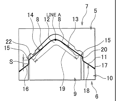
increases in
the use of panel parts (hood panels, fender panels, etc.) made of aluminum
base alloy. A
panel material made of aluminum base alloy (a panel material made of aluminum
base
alloy will be simply referred to as an "aluminum material" in the following
description,
although it will be sometimes referred simply to as a "panel material") has a
yield
strength and a tensile strength that are at substantially the same levels as
those of
commonly used mild steels. Meanwhile, an elongation and a strain value (r
value) of
the aluminum material are lower than those of the commonly used mild steels.
Accordingly, the aluminum material and the mild steels are greatly different
from each
other in the manner in which they respond to the press forming. A lot of
attention is
required when the aluminum material is pressed into shapes. Generally, as
shown in
FIG. 9, when an aluminum material 11 is pressed into shapes to form a fender
panel 1, a
press direction and a die face, which are used during the press forming, are
set using a
plain face Q including three points P1, P2, and P3 of the fender panel 1, as a
reference
face. In this case, the limit to which the aluminum material 11 can be drawn
is
approximately 200 mm (i.e., the aluminum material 11 can be drawn by 200 mm at
the
maximum). In addition, changes in the cross section of the aluminum material
1, which
occur due to the press forming, need to be limited to prevent crinkling and
cracking. As
CA 02622770 2008-03-13
WO 2007/039817 PCT/IB2006/002858
2
a result, the design of the fender panel 1 is significantly lirnited.
[0003] Recently, the variety of design of vehicle bodies has been increasing.
Due
to such increases, a dimension of the fender panel 1, produced by the press
forming, on a
given plane face when viewed from the top of the fender panel 1 (hereinafter,
such
dimension will be referred to as a "plane dimension") may be equal to or
greater than 500
mm. When the aluminum material 11 is pressed into shapes to form the fender
panel 1
having a great plane dimension, a maximum drawing depth S 1, at which the
aluminum
material 11 is drawn by the maximum amount (see FIG. 9), significantly exceeds
the limit
to which the aluminum material 11 can be drawn. As a result, cracking occurs.
Also,
when the aluminum material 11 is pressed into shapes to form the fender panel
1 having a
great plane dimension, the press forming is started from the center of a
portion at which
the aluminum material 11 is drawn by the maximum amount. Accordingly, as shown
in
FIG 10, the portion of the aluminum material 11, which will be the fender
panel 1, is not
pressed uniformly. In addition, a punch (a lower die) and the aluminum
material 11
contact each other at a point. As a xesult, crinkling occurs in a product.
Clinking and
cracking can be prevented to some extent by, for example, appropriRt~ly
arranging the die
face and an addendum shape portion and adjusting the amount of flow of the
material
caused by the press forming. However, when the cross section of a bent portion
greatly
changes, for example, when the fender panel 1 having a great plane dimension
is formed
from the aluminum material 11, occurrence of clinking and cracking cannot be
prevented.
[0004] Japanese Patent Application Publication No. JP-A-2004-188445 describes
a
method for pressing an aluminum base alloy plate into shapes. According to
this
method, an end portion of the aluminum base alloy plate is bent in advance to
form a bent
portion. This bending process is performed so that, a portion, that is
included in the end
portion of the aluminum base alloy plate, the end portion being formed into
the bent
portion, and that is in contact with a binder surface (die face) during the
press forming, is
roughly conformed to a surface of a blank holder during the press forming.
Then, the
aluminum base alloy plate is pressed into shapes, while blank holding is
performed on the
aluminum base alloy plate including the portion of the bent portion, which is
in contact
CA 02622770 2008-03-13
WO 2007/039817 PCT/IB2006/002858
3
with the binder surface during the press forming. However, the described
method does
not make it possible to uniform the drawing depth if the cross section of the
bent portion
greatly changes, for example, if the fender panel 1 having a great plane
dimension is
formed from the aluminum base alloy plate. As a result, the portion of the
aluminum
base alloy plate 11, which will be the fender panel 1, is not pressed
uniformly, causing
crinkling in a product, If superplastic forming (blow forming) is adopted
here, the
fender panel 1 made of aluminum base alloy, which has a great plane dimension
and
high-quality, can be produced. However, aluminum material for superplastic
forming is
more expensive than aluminum material for press forming. As a result,
performing
superplastic forming increases production cost.
[0005] In addition, the cycle time of the superplastic forming is longer than
that of
the press forming. Therefore, performing the superplastic forming
significantly reduces
the production efficiency (for example, although the cycle time when the
fender panel 1
made of aluminum base alloy is produced by press forming is 7.5 seconds per
one piece,
the cycle time when the fender panel 1 made of aluminum base alloy is produced
by
superplastic forming is 5 minutes per one piece). Alternatively, the;.fender
panel 1 may
be produced by brazing a plain face portion and a side face portion to each
other, which
are individually formed by press forming. However, this method does not
provide any
of high quality, high production efficiency (the cycle time when the fender
panel 1 made
of aluminum base alloy is produced by this method is three hours per one
piece) and high
cost performance (multiple types of dies are required).
DESCRIPTION OF THE INVENTION
[0006] The invention is made in light of the above-described circumstances.
The
invention provides a press forming method with which flexibility in the design
of panel
parts, formed by pressing aluminum materials into shapes, is increased. The
invention
also provides a press forming device with which flexibility in the design of
panel parts,
formed by pressing aluminum materials into shapes, is increased.
[0007] A first aspect of the invention relates to a method for press-forming a
panel
CA 02622770 2008-03-13
WO 2007/039817 PCT/IB2006/002858
4
part having a bent portion. According to the method, a panel material is bent
along a
portion, which will be the bent portion of the panel part, so that the panel
material is
placed along a forming face of a punch. A restraint-target portion of the
panel material,
which is set along the periphery of the panel material, is restrained with the
panel
material placed along the forming face of the punch. An addendum shape portion
of the
panel material, which is set on the inner side of the restraint-target portion
and which
surrounds a to-be-product portion of the panel material, is drawn by an amount
that is
equal to or less than the limit to which the panel material can be drawn so
that the
to-be-product portion of the panel material is roughly conformed to the
forming face of
the punch. Then, the to-be-product portion of the panel material is stretched
or drawn
so that the to-be-product portion is formed into a product shape.
[0008] In the method according to the first aspect of the invention, the
restraint-target portion of the panel material may be restrained onto a die
face that is
parallel to a plane extending from the forming face of the punch.
[0009] In the method according to the first aspect of the invention, the panel
material
is bent along an apex portion of the punch so that the panel material is
divided into two
portions that are contiguous with each other.
[0010] A second aspect of the invention relates to a press forming device
provided
with a press forming die that includes an upper die and a lower die, and that
forms a
panel part having a bent portion. The press forming die includes a restraining
portion, a
drawing portion, and a product forming portion. The restraining portion
restrains a
restraint-target portion of a panel material, which is set along the periphery
of the panel
material, with a portion of the panel material, which will be the bent portion
of the panel
part, bent along an apex portion of a punch. The drawing portion draws an
addendum
shape portion of the panel material, which is set on the inner side of the
restraint-target
portion and which surrounds a to-be-product portion of the panel material, by
an amount
equal to or less than the limit, to which the panel material can be drawn,
with the
restraint-target portion of the panel material restrained by the restraining
portion. The
to-be-product portion of the panel material is roughly conformed to the punch
by drawing
CA 02622770 2008-03-13
WO 2007/039817 PCT/IB2006/002858
the addendum shape portion o9f the panel material using the drawing portion.
The
product forming portion stretches or draws the to-be-product portion of the
panel material
with the to-be-product portion of the panel material roughly conformed to the
punch.
[0011] In the press forming device according to the second aspect of the
invention,
5 the restraining portion may have a die face that is parallel to a plane
extending from a
forming face of the punch.
[0012] In the press forming device according to the second aspect of the
invention,
the punch may have two forming faces that are defined by the apex portion
which
horizontally extends. The product forming portion that forms one of two
contiguous
faces of the panel part, which are defined by the bent portion, may be formed
in one of
the two forming faces. The product forming portion that forms the other of the
two
contiguous faces of the panel part, which are defined by the bent portion, may
be formed
in the other of the two forming faces.
[0013] With the press forming method and press forming device described above,
the
portion of the panel material, which will be the bent portion of the panel
part, is bent
along the apex portion of the punch. In this state, the restraint-target
portion of the
AE
panel material is restrained, and the addendum shape portion of the panel
material is
drawn by the amount equal to or less than the limit to which the panel
material can be
drawn. Thus, the to-be-product portion of the panel material is conformed to
the
forming face of the punch. Next, the to-be-product portion of the panel
material is
stretched or drawn by the product forming portion of the press forming die,
whereby the
to-be-product portion is formed into a product shape.
[0014] When the restraint-target portion of the panel material is restrained
by the
restraining portion, the cross section of the panel material does not change.
Accordingly,
crinkling does not occur when the restraint-target portion is restrained.
[0015] The panel part having two contiguous faces that are defined by the bent
portion is formed.
[0016] The invention thus provides the press forming method and press formi.ng
device with which flexibility of the design of the panel parts, formed by
pressing panel
CA 02622770 2008-03-13
WO 2007/039817 PCT/IB2006/002858
6
materials (aluminum materials) into shapes, is increased.
BRIEF DESCRIPTION OF THE DRAWINGS
[0017] The features, advantages thereof, and technical and industrial
significance of
the invention will be better understood by reading the following detailed
description of an
example embodiment of the invention, when considered in connection with the
accompanying drawings, in which:
FIG. 1 is the perspective view of a fender panel (a panel part) that is fonned
by a press
forming device according to an embodiment of the invention;
FIG 2 is the perspective view of an aluminum material from which the fender
panel
has been formed by the press forming device according to the embodiment of the
invention;
FIG 3 is the perspective view of a lower die of the press forming device
according to
the embodiment of the invention, showing the state where the aluminum material
is to be
restrained onto the lower die;
FIG 4 is the perspective view of the lower die of the press forming device
according
to the embodiment of the invention, showing the state where press forming has
been
completed;
FIG 5 is the view for describing the press forming device according to the
embodiment of the invention, showing the state where a restraint-target
portion of the
aluminum material has been restrained by a restraining portion;
FIG 6 is the view showing the state where an addendum shape portion of the
aluminum material has been drawn using a drawing portion, the state shown in
FIG 6
being realized subsequent to the state shown in FIG 5;
FIG 7 is the view showing the state where the fender panel has been formed
from a
to-be-product portion of the aluminum material by a product forming portion
which is
realized when an upper die and the lower die are pressed to each other, the
state shown in
FIG. 7 being realized subsequent to the state shown in FIG 6;
FIG. 8 is the perspective view of the aluminum material in the state shown in
FIG. 6;
CA 02622770 2008-03-13
WO 2007/039817 PCT/IB2006/002858
7
FIG. 9 is the view for describing a conventional method for press-forming a
panel part;
and
FIG. 10 is the view showing changes in the cross section of a panel part
formed by the
conventional forming method.
DETAILED DESCRIPTION OF THE EXAMPLE EMBODIMENT
[00181 In the following description and the accompanying drawings, the
invention
will be described in more detail with reference to an example embodiment. The
embodiment of the invention will be described in detail with reference to
FIGS. 1 to S.
In the embodiment of the invention, a press forming device that forms a fender
panel 1
made of aluminum base alloy (hereinafter, simply referred to as a "fender
panel 1")
shown in FIG 1 will be described. As shown in FIG 1, the fender panel 1(a
panel part)
is bent along a bent portion 2, which defines a plain face portion 3 and a
side face portion
4 that are contiguous with each other. The fender panel I is formed so as to
have a
plane dimension L (in the embodiment, the plane dimension L is 630 mm). The
press
forming device includes an upper die 5 (see FIG 5) and a lower die 6 (see FIG.
3). The
press forming device is provided with a press forming die 7. At the press
forming die 7,
the orientation of the fender panel 1 is set with respect to the press
direction in which the
press forming is performed (the vertical direction in FIG 2) so that a to-be-
product
portion 19 (a portion that will be formed into a product or an area including
the portion
that will be formed into the product) of a panel material 11 made of aluminum
base alloy
(a panel material made of aluminum base alloy will be simply referred to as an
"aluminum material 11" in the following description, although it will be
sometimes
referred simply to as a "panel material 11") is pressed uniformly (the to-be-
product
portion 19 of the aluminum material 11 is drawn by the minimum amount), as
shown in
FIG 2. As shown in FIG. 4, the lower die 6 includes a punch 9 having forming
faces 8,
and a cushion ring 10 which has a frame-shape and which is arranged so as to
surround
the punch 9. The punch 9 has an apex portion 12 that supports a portion of the
aluminum material 11, which will be the bent portion 2 of the fender panel 1.
The
CA 02622770 2008-03-13
WO 2007/039817 PCT/IB2006/002858
8
portion of the aluminum material 11, which will be the bent portion 2 6f the
fender panel
1, is bent along a line A (see FIG. 2).
[0019] Also, as shown in FIG 3, the punch 9 has a first face 13 (one of the
forming
faces) and a second face 14 (the other forming face) on the respective sides
of the line A
(on the right side and left side of the line A in FIG. 3). Each of the first
face 13 and the
second face 14 is tilted by a given tilt angle. From among the forming faces
8, the
forming face 8 used to form the plain face portion 3 (one of the faces, see
FIG. 1) of the
fender panel 1 is formed in the first face 13. From among the forming faces 8,
the
forming face 8 used to form the side face portion 4 (the other face, see FIG
1) of the
fender panel 1 is formed in the second face 14. In addition, an addendum shape
portion
support face 22, which is formed into a shape of a frame having a
predetermined width, is
set along the periphery of the upper portion of the punch 9. As shown in FIG
5, the
press forming die 7 has restraining portions 18 that restrain a restraint-
target portion 16 of
the aluminum material 11. The restraining portions 18 are tilted by the tilt
angles that
are equal to the angles by which the first face 13 and the second face 14 of
the punch 9
are tilted, respectively. Thus, when the restraint-target portion L6 of the
aluminum
material 11, which is supported by the lower die 6 so as to be placed along
the punch 9, is
restrained by the restraining portions 18 (each restraining portion 18
includes a
restraining face of the upper die 5 and a die face 17 of the cushion ring 10),
the cross
section of the aluminum material 11 does not change. Thus, as shown in FIG. 6,
the
to-be-product portion 19 of the alunvinum material 11 and the restraint-target
portion 16
of the aluminum material 11 are parallel to each other, while the to-be-
product portion 19
of the aluminum material 11 is roughly conformed to the forming faces 8 of the
punch 9.
[0020] With the press forming device according to the embodiment of the
invention,
the upper die 5 is moved downward after the restraint-target portion 16 of the
aluminum
material 11 is restrained by the restraining portions 18. Then, the cushion
ring 10 is
pressed downward by the upper die 5, and an addendum shape portion 20 set
around the
to-be-product -portion 19 of the aluminum material 11 is drawn by a drawing
portion 15
of the press forming die 7 by a drawing amount S, which is equal to or less
than the limit
CA 02622770 2008-03-13
WO 2007/039817 PCT/IB2006/002858
9
to which the aluminum material 11 can be drawn (in the embodiment, 'the limit
to which
the aluminum material 11 can be drawn is 200 nun). Thus, as shown in FIG. 6,
the
aluminum material 11 is elongated and pulled between the line A and the
addendum
shape portion 20, whereby the to-be-product portion 19 of the aluminum
material 11 is
roughly conformed to the forming faces 8 of the punch 9. While the to-be-
product
portion 19 of the aluminum material 11 is roughly conformed to the forming
faces 8 of
the punch 9, the upper die 5 and the lower die 6 are pressed to each other,
whereby a
product forming portion 21 is realized in the press forming die 7. Thus, the
to-be-product portion 19 of the aluminum material 11 is stretched or drawn by
the
minimum amount. As a result, the to-be-product portion 19 of the aluminum
material
11 is formed into a product shape (fender panel 1), as shown in FIG. 2 and FIG
7.
[0021] FIG 5 shows a line-length L1, and FIG 7 shows a line-length L2. The
line-length L1 is a line-length of a predeterniined portion of the aluminum
material 11,
which will undergo the press forming. The line-length L2 is a line-length of
the
predetermined portion of the aluminum material 11, which has undergone the
press
forming. With the press forming device according to the embodiment of the
invention,
the line-length L2 of the predetermined portion of the aluminum material 11,
which has
undergone the press forming (see FIG 7), is equal to or less than 1.25 times
of the
line-length L1 of the predetermined portion of the aluminum material 11, which
will
undergo the press forming (L2 < Ll x 1.25). Accordingly, cracking in the to-be-
product
portion 19 of the aluminum material 11 is prevented from occurring during the
press
forming.
[0022] Next, the effects of the press forming device according to the
embodiment of
the invention will be described. The press forming device is provided with the
press
forming die 7. At the press forming die 7, the orientation of the fender panel
1 (panel
part) is set with respect to the press direction so that the to-be-product
portion 19 of the
aluminum material 11 is pressed uniformly (the to-be-product portion 19 of the
aluminum
material 11 is drawn by the minimum amount). First, the alumin.um material 11
is
placed between the upper die 5 and the lower die 6 so as to be horizontally
supported on
CA 02622770 2008-03-13
WO 2007/039817 PCT/IB2006/002858
the lower die 6, while the press forming die 7 is open (while the upper die 5
is at the
position at which it has been moved upward to the fullest extent). Next, the
upper die 5
is moved downward. Then, the aluminum material 11 is bent along the portion,
which
will be the bent portion 2 of the fender panel 1, whereby the aluminum
material 11 is
5 roughly conformed to the first face 13 and the second face 14 of the punch
9. In this
state, as shown in FIG. 5, the restraint-target portion 16 of the aluminum
material 11 is
restrained (supported) by the restraining portions 18 (each restraining
portion 18 includes
the restraining face of the upper die 5 and the die face 17 of the cushion
ring 10) of the
press forming die 7.
10 [0023] Next, while the restraint-target portion 16 of the aluminum material
11 is
restrained, as shown in FIGS. 6 and 8, the cushion ring 10 is pressed downward
by the
upper die 5, and the addendum shape portion 20 of the aluminum material 11
(the outer
portion in the addendum shape portion 20, namely, the portion of the addendum
shape
portion, which is adjacent to the restraint-target portion 16) is drawn by the
drawing
portion 15 of the press forming die 7. At this time, the addendum shape
portion 20 is
drawn by the amount equal to or less than the limit to which the aluminum
material 11
can be drawn (in the embodiment, the limit to which the aluminum material 11
can be
drawn is 200 mm). Thus, the aluminum material 11 is elongated and pulled
between the
line A and the addendum shape. portion 20, and the to-be-product portion 19 of
the
aluminum material 11 is roughly conformed to the forming faces 8 of the punch
9.
When the addendum shape portion 20 of the aluminum material 11 is drawn by the
drawing portion 15 of the press forming die 7, the material flows in the
addendum shape
portion 20, which may cause crinkling in the addendum shape portion 20 (more
specifically, the portion in the addendum shape portion 20, which corresponds
to "S" and
which has been drawn by drawing portion 15). However, because the crinkling
occurs
outside the to-be-product portion 19 of the aluminum material 11, it does not
affect the
quality of the product.
[0024] In this state, as shown in FIG. 7, the upper die 5 and the lower die 6
of the
press forming die 7 are pressed to each other to realize the product forming
portion 21 in
CA 02622770 2008-03-13
WO 2007/039817 PCT/IB2006/002858
11
the press forming die 7. Thus, the to-be-product portion 19 of the alurninum
material 11,
which has been roughly conformed to the punch 9, is stretched or drawn. As a
result, as
shown in FIG 2, the to-be-product portion 19 is formed into the product shape
(fender
panel 1).
[0025] The embodiment of the invention produces the following effects. The
orientation of the fender panel 1 is set with respect to the press direction
in which the
press foxming is performed (the vertical direction in FIG. 2) so that the to-
be-product
portion 19 of the aluminum material 11 is pressed uniformly (the to-be-product
portion
19 of the aluminum material 11 is drawn by the minimum amount). Then, the
aluminum material 11 is bent along the portion in the aluminum material 11,
which will
be the bent portion 2 of the fender panel 1, and roughly conformed to the
punch 9 of the
press forming die 7. Also, the restraint-target portion 16 of the aluminum
material 11 is
restrained (supported) by the restraining portioins 18 of the press forming
die 7. Then,
the addendum shape portion 20 of the aluminum material 11 (more specifically,
the outer
portion in the addendum shape portion 20) is drawn by the drawing portion 15
of the
press forming die 7 by the amount that is equal to or less than the limit to
which the
aluminum material 11 can be drawn. Thus, the aluminum material 11 is elongated
and
pulled between the line A (see FIG. 3) and the addendum shape portion 20, and
the
to-be-product portion 19 of the aluminum material 11 is roughly conformed to
the
forming face 8 of the punch 9. In this state, the upper die 5 and the lower
die 6 of the
press forming die 7 are pressed to each other to realize the product forming
portion 21 in
the press forming die 7. Thus, the to-be-product portion 19 of the aluminum
material 11,
which has been roughly conformed to the punch 9, is stretched or drawn,
whereby the
fender panel 1 is formed in the to-be-product portion 19.
[0026] According to the embodiment of the invention, the to-be-product portion
19
of the aluminum material 11 is stretched or drawn with the to-be-product
portion 19
roughly conformed to the forming faces 8 of the punch 9. Accordingly, the
cross section
of the to-be-product portion 19 uniformly changes by the minimum amount. As a
result,
inconvenience such as crinkling and crocking does not occur, which makes it
possible to
CA 02622770 2008-03-13
WO 2007/039817 PCT/IB2006/002858
12
produce the fender panel 1(panel part) having high quality.
[0027] According to the embodiment of the invention, the restraining portions
18
(each restraining portion 18 includes the restraining face of the upper die 5
and the die
face 17 of the cushion ring 10) are tilted by the tilt angles that are equal
to the angles by
which the first face 13 and the second face 14 of the punch 9 are tilted,
respectively.
Accordingly, when the restraint-target portion 16 of the aluminum material 11
is
restrained by the restraining portions 18, the cross section of the aluminum
material 11
does not change. As a result, occurrence of crinkling in the aluminum material
11 is
prevented.
[0028] According to the embodiment of the invention, the addendum shape
portion
is set so as to surround the to-be-product portion 19. Accordingly, flow of
the
material due to changes in the cross section of the to-be-product portion 19
is absorbed
by the addendum shape portion 20. Thus, inconvenience such as crinkling and
cracking
does not occur in the to-be-product portion 19, which makes it possible to
produce the
15 fender panel 1(panel part) having high quality.
[0029] According to the embodiment of the invention, the addendum shape
portion
20 of the aluminum material 11 is drawn by the drawing portion 15 of the press
forming
die 7. Accordingly, even if the material of the addendum shape portion 20
flows and
crinkling occurs in the addendum shape portion 20, crinkling does not occur in
the
20 to-be-product portion 19 (fender panel 1).
[0030] According to the embodiment of the invention, the addendum shape
portion
20 is drawn by the amount S which is equal to or less than the limit to which
the
aluminum material 11 can be drawn. Accordingly, the addendum shape portion 20
does
not rupture.
[0031] According to the embodiment of the invention, the line-length L2 of the
portion of the aluminum material 11, which has undergone the press forming, is
equal to
or lower than 1.25 times of the line-length Ll of the portion of the aluminum
material 11,
which will undergo the press forming. Accordingly, cracking does not occur in
the
to-be-product portion 19 during the press forming.
CA 02622770 2008-03-13
WO 2007/039817 PCT/IB2006/002858
13
[0032] According to the embodiment of the invention, it is possible to
produce, by
the press forming, the fender panel 1 made of aluminum base alloy, having a
great plane
dimension L and high quality. With the press forming device and press forming
method
according to the embodiment of the invention, flexibility in the design of the
panel parts
is increased, the panel parts are produced efficiently, and the production
cost is
significantly reduced as compared to the conventional method.
[0033] The embodiment is not limited to the above. For example, the embodiment
may be modified as follow.
[0034] In the embodiment described above, the fender panel 1 is described as
the
panel part. However, the invention may be applied to production of any types
of panel
parts such as a door panel, as long as the panel part is bent along a bent
portion, which
defines two faces that are contiguous with each other (corresponding to the
plain face
portion 3 and the side face portion 4 in the embodiment of the invention).