Note: Descriptions are shown in the official language in which they were submitted.
CA 02622810 2012-02-17
WO 2007/038426 PCT/US2006/037242
PNEUMATIC BIASING OF A LINEAR ACTUATOR AND
IMPLEMENTATIONS THEREOF
FIELD OF TIIE INVENTION
[0002] This invention relates to linear actuators, and more particularly to
mechanical
linear actuators, suitable for use in machinery such as metal forming presses,
shears, brakes,
and die cushions.
BACKGROUND OF THE INVENTION
[0003] Modern manufacturing practices often require machinery including linear
actuators, for cutting, forming, punching, and/or joining together components
formed from
raw materials in a variety of forms, such as sheets, bar stock, billets, or
pellet. Such
machinery is often required to apply substantial compression loads, of, for
example, 75 to
100 tons, and be capable of rapid cycle times, to promote efficient,
effective, low cost
production.
[0004] High capacity machinery, of the type used in cutting and forming motor
vehicle
body panels and the like, for example, typically have first and second
structures in the form
of upper and lower platens, each carrying part of a die set. The upper platen
and upper die
are typically driven vertically in a reciprocating motion by a drive mechanism
including
some form of linear actuator. The lower platen and lower die are generally
stationary, but
in some widely used types of metal forming machinery, a die cushion mechanism
may be
provided, adjacent the lower platen, for clamping an outer perimeter of a
sheet of material
being formed by the die set. Such die cushion mechanisms may also include a
plurality of
linear actuators for maintaining the clamping pressure on the edges of the
work piece, as the
work piece moves vertically during formation by the die set.
CA 02622810 2008-03-14
WO 2007/038426 PCT/US2006/037242
[0005] In the past, linear actuators of the type used in material forming
machinery were
primarily hydraulic and/or pneumatic actuators. Hydraulic and/or pneumatic
actuators are
typically capable of producing high operating forces at reasonably high cycle
rates over a
relatively long operating life of the machine. Hydraulic and/or pneumatic
actuators are
sometimes rather large in physical size, however, and require auxiliary
equipment, such as
pumps, valves, fluid tanks, and fluid cooling devices, which also are rather
large in physical
size. Hydraulic actuators often require considerable maintenance, and are
prone to leakage
over the operational life of the machine. Pneumatic actuators typically are
incapable of
being controlled, to the degree required for modem die press operations.
[0006] As material forming methods have become more sophisticated,
mechanically
driven actuators, having mechanisms such as ball screws, roller screws, or
rack-and-pinion
arrangements, for example, have begun to supplant traditional hydraulic
actuators. Such
mechanical actuators are typically smaller in physical size, than a
corresponding hydraulic
actuator, and may be capable of more rapid response and have greater
controllability than
hydraulic actuators. Mechanical actuators also eliminate the problem of fluid
leakage
inherent in the use of hydraulic actuators. U.S. Patent publications
disclosing mechanical
actuators for use in material forming machinery include: 5,522,713, to Lian;
5,435,166, to
Sunada; 6,640,601 B2, to Hatty; 5,656,903, to Shui, et al.; and US
2006/0090656 Al, to
Iwashita, et al.
[0007] In a sophisticated die cushion apparatus, for example, a plurality of
linear
actuators may be closely positioned to one another around the perimeter of the
workpiece.
As the workpiece is formed, the clamping pressure applied by individual ones
of the linear
actuators may be varied, by a numerical control apparatus for example, to
allow movement
of material in selected sections of the periphery to preclude tearing or
wrinkling of the
workpiece during the forming process. To allow for such close positioning of
the linear
actuators, the individual actuators must be small in physical size. It is also
desirable, that if
one of the plurality of linear actuators should need to be repaired or
replaced, that the
individual linear actuators be modular in nature to facilitate removal and
replacement of the
defective actuator so that production on the material forming machine having
the die
cushion may be resumed as quickly as possible. It would be desirable to use
mechanical
actuators in such applications, rather than hydraulic actuators, due to the
smaller size and
more inherently modular construction of mechanical actuators, compared to
hydraulic
actuators.
2
CA 02622810 2008-03-14
WO 2007/038426 PCT/US2006/037242
[0008] Despite their significant inherent advantages, in a number of respects,
over
hydraulic actuators, the use of mechanical actuators in material forming
machinery has been
limited to date, due to wear and fatigue failure of the mechanical components
of the
mechanical actuator resulting from the large forces and cyclical loading on
the mechanical
components, inherent with the use of linear actuators in material forming
machinery.
[0009] It is desirable, therefore, to provide improved apparatuses and methods
for
utilizing mechanically driven linear actuators in material forming machinery,
in a manner
which overcomes the problems addressed above. It is also desirable to provide
such
improved apparatuses and methods in a form which may be readily adapted for
use as a
primary linear actuator, in a platen press or a metal cutting shear, for
example, and in
applications, such as a die cushion mechanism, having a plurality of linear
actuators
performing a secondary clamping function in conjunction with one or more
primary linear
actuators providing a primary force for a material forming operation. It is
further desirable,
that such an improved apparatus and method also be in a form which is readily
controllable
and/or reconfigurable so that a given material forming machine may be
conveniently used
for a variety of operations, and/or with die sets, for example, of varying
sizes and weights.
BRIEF SUMMARY OF THE INVENTION
[0010] The invention provides an improved method and apparatus for
constructing and
operating a linear actuator, or equipment incorporating a linear actuator, by
operatively
connecting a pressure biasing pneumatic arrangement between the driving member
and the
driven member of a mechanical linear actuator for applying a unidirectional
biasing force
between the driving and driven members, along an axis of motion, regardless of
the location
or movement of the driving and driven elements with respect to one another
along the axis
of motion.
[0011] Practice of the invention thereby precludes, reversal in the direction
of forces at
the juncture of the driving and driven member of the linear actuator as the
linear actuator
exerts a bi-directional force along the axis of motion between a first
structure and a second
structure. By virtue of this arrangement, backlash within the mechanical
actuator can be
substantially eliminated, with an attendant significant improvement in
operation and
reliability of the mechanical linear actuator.
[0012] In some forms of the invention, the pneumatic biasing arrangement is
also
configured to support substantially all of an operating load acting on the
actuator, thereby
3
CA 02622810 2008-03-14
WO 2007/038426 PCT/US2006/037242
substantially reducing operating loads imposed on the driving and driven
members and also
substantially reducing the level of operating force which must be exerted by
the driving and
driven members during operation of the mechanical linear actuator. The
pneumatic biasing
arrangement may further be configured, in some forms of the invention, to
preferentially aid
movement of the driven member in one direction, to thereby further reduce the
level of
operating force which must be exerted by the driving and driven members during
movement
of driving member in the preferred direction.
[0013] In some forms of a pneumatically biasable mechanical linear actuator,
according
to the invention, the driving and driven members, and the first and second
cylinder elements
are all coaxially disposed along the axis of motion, to thereby promote
efficient and
effective transfer of loads and forces within and applied by the actuator, and
also to thereby
provide a robust actuator of compact physical size and elegantly simple
construction and
operation. Such an actuator offers significant advantages over prior actuators
including, but
not limited to: improved operational performance, efficiency and
effectiveness; enhanced
reliability and life; reduced need for peripheral support equipment; modular
installation and
replacement; and the capability to fit multiple actuators into smaller spaces.
[0014] A pneumatically biasable linear actuator apparatus, according to the
invention,
may also include a control arrangement operatively connected to the pneumatic
biasing
arrangement for controlling the unidirectional biasing force. Such a control
arrangement
may take the form of a simple pressurizing source and valve arrangement, or
any other
appropriate form, including a numerically controlled apparatus for actively
controlling the
pneumatic biasing arrangement during operation of the mechanical linear
actuator.
[0015] In one form of the invention, a pneumatically biasable mechanical
linear
actuator apparatus is provided, for exerting a bi-directional force along an
axis of motion
between a first structure and a second structure, wherein at least one of the
structures is
movable along the axis of motion. The linear actuator apparatus includes at
least one
pneumatically biasable linear actuator having a driving and a driven member,
and a
pneumatic biasing arrangement. The driving and driven members are connected to
one
another in a mechanical drive arrangement for motion relative to one another
along the axis
of motion. The pneumatic biasing arrangement is operatively connected between
the
driving member and the driven member for applying a unidirectional biasing
force between
the driving and driven members, along the axis of motion, regardless of the
location or
movement of the driving and driven elements with respect to one another along
the axis of
motion.
4
CA 02622810 2008-03-14
WO 2007/038426 PCT/US2006/037242
[0016] The driving and driven members may apply an operating force to the
first and
second structures, with the pneumatic biasing arrangement maintaining the
unidirectional
biasing force between the driving and driven members regardless of the
direction or level of
operating force on the first and second structures, and regardless of relative
position or
motion of the first and second structures with respect to one another.
[0017] One form of a pneumatic biasing arrangement, according to the
invention,
includes first and second pneumatic cylinder elements which are connected to
one another
for reciprocal movement with respect to one another along the axis of motion.
The first and
second cylinder elements collectively define a fluid cavity therebetween, with
the cavity
defining a volume for receiving a pressurized fluid. The first cylinder
element is fixedly
attached to the driving element, for movement therewith along the axis of
motion, and the
second cylinder element is fixedly attached to the driven member for movement
therewith,
such that relative movement of the driven and driving members, with respect to
one another,
in one direction along the axis of motion, causes an increase in the volume of
the cavity, and
movement of the driven and driving elements, with respect to one another in an
opposite
direction along the axis of motion, causes a decrease in the volume of the
cavity.
[0018] A volume adjusting element may be movably disposed within the fluid
cavity for
modifying the volume of the cavity available for receiving pressurized fluid
in the cavity.
The volume control arrangement may also be configured for performing other
functions,
such as, but not limited to: adjusting the relationship between the stroke
length, and/or stoke
direction, of the linear actuator, and the change in pressure within the
cavity resulting from
the stroke; adjusting the axial length of the linear actuator; setting maximum
and/or
minimum operating pressures for the pressurized gas within the cavity; and/or,
setting a
desired maximum or minimum magnitude of the unidirectional biasing force.
[0019] In some forms of the invention, the unidirectional biasing force varies
in
magnitude, throughout the stroke of the linear actuator.
[0020] In some forms of the invention, the pneumatic biasing arrangement, of a
pneumatically biasable mechanical linear actuator, according to the invention,
may be
operated without applying a biasing force between the driving and driven
members of the
mechanical drive arrangement. The pneumatic biasing arrangement may be
configured and
operated to apply an offset force, for supporting some portion, or
substantially all of an
operating load acting on the actuator, substantially without applying a
biasing force between
the driving and driven members of a pneumatically biasable mechanical linear
actuator,
CA 02622810 2008-03-14
WO 2007/038426 PCT/US2006/037242
according to the invention, to thereby at least partially reduce operating
loads imposed on
the driving and driven members and also at least partially reduce the level of
operating force
which must be exerted by the driving and driven members during operation of
the
mechanical linear actuator.
[0021] A control arrangement maybe provided for controlling the amount of
pressurized gas in the volume. The control arrangement may adjust the amount
of
pressurized gas in the volume to maintain a desired level of unidirectional
biasing force,
during operation of the linear actuator. The volume adjusting element may also
function as
a linear length adjustment arrangement for adjusting a minimum linear maximum
length of
the actuator.
[0022] Some forms of the invention may utilize two or more pneumatically
biasable
mechanical linear actuators, according to the invention. A common control
arrangement
may be utilized for controlling the amount of pressurized gas in the volumes
of each of the
two or more linear actuators.
[0023] In some forms of the invention, a pneumatically biasable mechanical
linear
actuator, according to the invention, may be operated with, or without, an
amount of
pressurized gas being disposed within the volume of the pneumatic biasing
arrangement.
An amount of pressurized gas, sufficient for generating the unidirectional
biasing force
between the driving and driven members, may be disposed within the volume of
the
pneumatic biasing arrangement. Where application of driving force to the
driving member
generates a driving force in the driven member, the amount of pressurized gas
may be
controlled to generate sufficient pressure within the cavity for maintaining
the unidirectional
biasing force between the driving and driven members regardless of the
direction or level of
the driving force. Where the first and second structures apply an operating
load to the
actuator, the amount of pressurized gas in the cavity may generate sufficient
pressure within
the cavity for maintaining the unidirectional biasing force between the
driving and driven
members regardless of the direction or level of the operating load on the
actuator, and
regardless of relative position or motion of the first and second structures
with respect to
one another.
[0024] The driving and driven members, respectively, may be a rotatable screw
member
and a roller nut member of a roller screw apparatus, with the screw having a
rotational
center line thereof substantially defining the axis of motion and first and
second axial ends
thereof spaced axially from one another along the axis of motion. The roller
nut member
6
CA 02622810 2008-03-14
WO 2007/038426 PCT/US2006/037242
may have rotating inner members for engaging the screw, with the rotating
inner members
being operatively attached to and disposed within a non-rotating roller screw
housing. The
first cylinder element of the pneumatic biasing arrangement may be
substantially
symmetrically disposed about the axis of motion and may have the screw member
operatively attached thereto in a manner allowing rotation of the screw with
respect to the
first cylinder element, about the axis of rotation, while axially restraining
the screw against
axial movement of the screw with respect to the first cylinder element. The
first cylinder
element may further have first and second axial ends thereof, with the first
axial end of the
first cylinder element being disposed adjacent the first axial end of the
screw and the second
axial end of the first cylinder element being disposed adjacent the second
axial end of the
screw. The second axial end of the screw is configured as a closed surface, to
form a
stationary piston having an outer sealing periphery thereof.
[0025] The second cylindrical element, in the form of an axially movable
cylinder, may
have a wall thereof sealingly and slidingly engaging the sealing periphery of
the stationary
piston of the first cylinder member in such a manner that the wall of the
movable cylinder,
in conjunction with the stationary piston of the first cylinder member, form
the cavity and
define the volume within the cavity for receiving the pressurized gas. The
second
cylindrical element, in the form of the axially movable cylinder, is
operatively attached to
the first cylindrical element in a manner allowing the second cylindrical
element to move
axially with respect to the first cylinder element, but not rotate with
respect to the first
cylindrical element or the axis of motion. The second cylindrical element, in
the form of
the axially movable cylinder, also has first and second axial ends thereof,
with the first axial
end overlapping the first cylinder member and having the roller screw housing
fixedly
attached thereto in such a manner that the roller screw nut moves axially with
the movable
cylinder. The second axial end of the movable cylinder is closed by the wall
thereof.
[0026] The first cylindrical element is adapted for operatively bearing
against a
stationary one of the first and second structures, and the second cylindrical
element is
adapted for operatively bearing against the movable one of the first and
second structures.
[0027] A guide, extending from the first cylindrical element along the axis of
motion
and disposed about a portion of the second cylindrical member, maybe included,
for
guiding and supporting the second cylindrical element axially about the axis
of motion.
[0028] A drive motor may be operatively attached to the first end of the screw
for
rotating the screw about the axis of rotation. The motor may have a drive
shaft thereof
7
CA 02622810 2008-03-14
WO 2007/038426 PCT/US2006/037242
attached directly to the first end of the screw, for driving the screw, in
such a manner that
the motor, screw, roller nut member, and the first and second cylindrical
elements are all
substantially coaxial about the axis of motion. A brake may also be provided
for selectively
restraining the screw from rotating about the axis of rotation.
[0029] In some forms of the invention, the axis of motion is oriented
substantially
vertically. In some forms of the invention, the first end of the first
cylindrical element may
be attached to a stationary base of a material forming machine, with the
second end of the
second cylindrical element being disposed substantially vertically above the
first end of the
first cylindrical element.
[0030] The invention may also take the form of a method for pneumatically
biasing a
mechanical linear actuator apparatus for exerting a bi-directional force along
an axis of
motion between a first structure and a second structure, wherein at least one
of the
structures is movable along the axis of motion, and wherein the apparatus
includes at least
one pneumatically biasable linear actuator, according to the invention, having
a driving and
a driven member connected to one another in a mechanical drive arrangement for
motion
relative to one another along the axis of motion. The method may include
operatively
connecting a pneumatic biasing arrangement between the driving member and the
driven
member of the linear actuator, for applying a unidirectional biasing force
between the
driving and driven members, along the axis of motion, regardless of the
location or
movement of the driving and driven element with respect to one another along
the axis of
motion. The method may also include controlling the unidirectional biasing
force to a
desired value, using the pneumatic biasing arrangement. Where the driving and
driven
members apply an operating force to the first and second structures, a method,
according to
the invention, may further include operating the pneumatic biasing arrangement
in a manner
that maintains the unidirectional biasing force between the driving and driven
members
regardless of the direction or level of the operating force on the first and
second structures,
and regardless of the relative position or motion of the first and second
structures with
respect to one another.
[0031] The invention may also take the form of a material forming machine
having a
first and second structure, wherein at least one of the structures is movable
along an axis of
motion, and also having at least one pneumatically biasable linear actuator
apparatus,
according to the invention, operatively connecting the first and second
structures for
exerting a bi-directional force along the axis of motion between the first and
second
structures. The linear actuator may include a driving and a driven member
connected to one
8
CA 02622810 2008-03-14
WO 2007/038426 PCT/US2006/037242
another in a mechanical drive arrangement, for motion relative to one another
along the axis
of motion, and a pneumatic biasing arrangement operatively connected between
the driving
member and the driven member for applying a unidirectional biasing force
between the
driving and driven members, along the axis of motion, regardless of the
location or
movement of the driving and driven elements with respect to one another along
the axis of
motion.
[0032] A material forming machine, according to the invention, may take a
variety of
forms, including, but not limited to: a platen press; a shear; a brake; a
press for operating a
die set; a die cushion mechanism; a punch; an extrusion press; or a compaction
press for use
in forming components from pellets or chips of a material such as plastic, for
example.
[0033] Other aspects, objects, and advantages of the invention will be
apparent from the
following detailed description and accompanying drawings describing exemplary
embodiments of the invention.
DESCRIPTION OF THE DRAWINGS
[0034] The accompanying drawings incorporated into and forming part of the
specification illustrate several aspects of the present invention and,
together with the
description, serve to disclose and explain the invention. In the drawings:
[0035] FIGS. 1-3 are schematic cross-sectional illustrations of a first
exemplary
embodiment of a pneumatically biasable mechanical linear actuator apparatus,
according to
the invention, with FIG. 1 showing a linear actuator, according to the
invention, in an
extended position, FIG. 2 showing the exemplary embodiment of the linear
actuator in a
retracted position, and FIG. 3 illustrating a variation of the first exemplary
embodiment of a
pneumatically biasable mechanical linear actuator apparatus, according to the
invention,
which includes two pneumatically biasable linear actuators in accordance with
the
invention;
[0036] FIGS. 4-6 are schematic cross-sectional illustrations of a second
exemplary
embodiment of the invention, in the form of a pneumatically biasable
mechanical linear
actuator having a volume adjusting member disposed within a pressurized gas
cavity of the
actuator;
9
CA 02622810 2008-03-14
WO 2007/038426 PCT/US2006/037242
[0037] FIGS. 7 and 8 are side and end elevation views, respectively, of a
press,
according to the invention;
[0038] FIG. 9 is a side elevation view of a material forming machine,
according to the
invention, including a die cushion arrangement according to the invention;
[0039] FIGS. 10 and 11 are a side elevation and top view, respectively, of a
material
forming machine, according to the invention, having a die set attached thereto
for forming a
workpiece;
[0040] FIG. 12 is a perspective illustration of an alternate embodiment of a
pneumatically biasable mechanical linear actuator, according to the invention;
[0041] FIG. 13 is a top view of the exemplary embodiment of a linear actuator
of FIG.
12, having indicated thereupon section lines relating to FIGS. 14-16;
[0042] FIG. 14 is a cross-sectional illustration taken along lines 14-14 in
FIG. 13, of the
exemplary embodiment of the linear actuator shown in FIG. 12;
[0043] FIG. 15 is a cross-sectional illustration taken along lines 15-15 in
FIG. 13, of
the exemplary embodiment of the linear actuator shown in FIG. 12; and
[0044] FIG. 16 is a cross-sectional illustration taken along lines 16-16 in
FIG. 13, of
the exemplary embodiment of the linear actuator shown in FIG. 12.
[0045] While the invention will be described in connection with certain
preferred
embodiments, there is no intent to limit it to those embodiments. On the
contrary, the intent
is to cover all alternatives, modifications and equivalents as included within
the spirit and
scope of the invention as defined by the appended claims.
DETAILED DESCRIPTION OF THE INVENTION
[0046] FIGS. 1-3 illustrate a first exemplary embodiment of a pneumatically
biasable
linear actuator apparatus 100, for exerting a bi-directional force along an
axis of motion 102
between a first structure 104 and a second structure 106, wherein at least one
of the
structures 104, 106 is movable along the axis of motion 102. Specifically, in
the exemplary
embodiments illustrated in FIGS. 1-3, the first structure 104, represents a
stationary base of
CA 02622810 2008-03-14
WO 2007/038426 PCT/US2006/037242
a material forming machine, and the second structure 106 represents a movable
bridge or
platen of the material forming machine.
[0047] The first exemplary embodiment of the pneumatically biasable linear
actuator
100 includes one or more pneumatically biasable mechanical linear actuators
108, each
having a drive arrangement 110 including a driving member 112 and a driven
member 114.
Each of the pneumatically biasable mechanical linear actuators 108, of the
first exemplary
embodiment, also includes a pneumatic biasing arrangement 116 operatively
connected
between the driving member 112 and the driven member 114 of the drive
arrangement 110.
The driving and driven members 112, 114 are operatively connected to one
another, within
the mechanical drive arrangement 110, for motion relative to one another along
the axis of
motion 112. Specifically, in the first exemplary embodiment 100, the driven
member 114 is
moved linearly along the axis of motion 102 by the driving member 112.
[0048] As described in more detail below, the pneumatic biasing arrangement
116 is
operatively connected between the driving member 112 and the driven member
114, for
applying a unidirectional biasing force between the driving and driven members
112, 114
along the axis of motion 102, regardless of the location or movement of the
driving and
driven elements 112, 114 with respect to one another, along the axis of motion
102.
[0049] The pneumatic biasing arrangement 116, of the first exemplary
embodiment 100,
includes first and second cylinder elements 118, 120, which are connected to
one another,
for reciprocal movement with respect to one another along the axis of motion
102. The first
and second cylinder elements 118, 120 are also configured for collectively
defining a fluid
cavity 122 between the first and second cylinder elements 118, 120, with the
cavity 122
defining a volume for receiving a pressurized fluid.
[0050] The first cylinder element 118 is fixedly attached to the driving
member 112.
The second cylinder element 114 is fixedly attached to the driven member 114,
for
movement therewith along the axis of motion, such that relative movement of
the driven
and driving members 112, 114 with respect to one another in one direction
along the axis of
rotation causes an increase in the volume of the cavity 122, and movement of
the driven and
driving members with respect to one another in an opposite direction along the
axis of
rotation 102 causes a decrease in the volume of the cavity 122.
[0051] In the first exemplary embodiment 100, the driving and driven members
112,
114 are, respectively, a rotatable screw member 112 and a roller nut member
114 of a roller
11
CA 02622810 2008-03-14
WO 2007/038426 PCT/US2006/037242
screw apparatus 110. The screw 112 has a rotational center line thereof which
substantially
defines the axis of motion 102, and first and second axial ends 124, 126
thereof spaced
axially from one another along axis of motion 102. The roller nut member 114
includes a
plurality of rotating intermembers 128, as is known in the art, for engaging
the screw 112,
with the rotating intermembers 128 being operatively attached to and disposed
within a non-
rotating roller screw housing 130.
[0052] Those having skill in the art, will recognize that the roller screw
drive
arrangement 110, of the exemplary embodiment 100, is of typical construction
for such
devices. A roller screw was selected for the drive arrangement 110 in the
exemplary
embodiment 100, because roller screw drive arrangements typically are capable
of handling
larger static loads at high screw speeds and offer longer life than comparably
sized
alternative drive mechanisms, such as ball screws. Roller screw drive
arrangements, of a
type suitable for practicing the invention are manufactured by SKF Motion
Technologies,
Bethlehem, Pennsylvania, USA. Those having skill in the art will recognize,
however, that
in alternate embodiments, the present invention maybe practiced with a variety
of other
types of drive arrangements 110, including, but not limited to: ball screws,
Acme screws;
rack-and-pinion gear arrangements, etc.
[0053] The first cylinder element 118 of the pneumatic biasing arrangement 116
forms a
first cylinder member 118 disposed about the axis of motion 102, and having
the screw
member 112 operatively attached thereto in a manner allowing rotation of the
screw 112
with respect to the first cylinder member 118 about the axis of rotation 102,
while axially
restraining the screw 112 against axial movement of the screw 112 with respect
to the first
cylinder member 118. In the first exemplary embodiment 100, the axial
restraint of the
screw 112 to the first cylinder member 118 is illustrated by a thrust bearing
132 operatively
connected between the screw 112 and the first cylinder member 118 at the first
axial end
124 of the screw 112.
[0054] The first cylinder element, 118, in the exemplary embodiment 100,
further has
first and second axial ends 134, 136 thereof, with the first axial end 134 of
the first cylinder
member 118 being disposed adjacent to the first axial end 124 of the screw
112, and the
second axial end 136 of the first cylinder member 118 being disposed adjacent
the second
axial end 126 of the screw 112. The second axial end 136 of the first cylinder
member 118
is configured as a closed surface to form a stationary piston 136 having an
outer sealing
periphery 138 thereof.
12
CA 02622810 2008-03-14
WO 2007/038426 PCT/US2006/037242
[0055] The second cylindrical element, in the form of an axially movable
cylinder 120,
has a wall 140 thereof which sealingly and slidingly engages the sealing
periphery 138 of
the stationary piston 136 of the first cylinder member 118, such that the wall
140 of the
movable cylinder 120, in conjunction with the stationary piston 136 of the
first cylinder
member 118, form the cavity 122 and define the volume for receiving the
pressurized gas.
The movable cylinder 120 is operatively attached to the first cylinder member
118 in a
manner allowing the axially movable cylinder 120 to move axially with respect
to the first
cylinder member 118, but not rotate with respect to either the first cylinder
member 118 or
the axis of motion 102.
[00561 The axially movable cylinder 120 also has first and second axial ends
142, 144
thereof. The first axial end 142, of the axially movable cylinder 120,
overlaps the first
cylinder member 118, and has the roller screw housing 130 attached thereto in
such a
manner that the roller screw nut 114 moves axially with the movable cylinder
120. The first
cylinder member 118 and first axial end of the movable cylinder 120 are vented
to the
atmosphere, to preclude any build-up of pneumatic pressure below the piston
136 at the
second axial end of the first cylinder member 118.
[0057] The second axial end 144 of the movable cylinder 120 is closed, to form
a load
bearing surface, and form part of the wall 140 and closing the cavity 122. The
first axial
end 134 of the first cylinder member 118 is adapted for operatively bearing
against the
stationary structure 104, and the second axial end 144 of the axially movable
cylinder 120 is
adapted for operatively bearing against the movable second structure 106.
[00581 The pneumatically biasable mechanical linear actuator 108, of the first
exemplary embodiment 100, includes a drive motor 146, having a drive shaft 148
thereof
attached to the first axial end 124 of the screw member 112, for rotating the
screw member
112 about the axis of rotation substantially coincident with the axis of
motion 102.
[00591 By virtue of the construction described thus far, it will be seen that,
in the
pneumatically biasable mechanical linear actuator apparatus 108 of the first
exemplary
embodiment 100, all of the components described thus far are coaxially located
with respect
to one another, along and about the axis of motion 102. This coaxial
arrangement provides
a highly compact and robust, straightforward, actuator construction, and
promotes efficient
and effective operation of the actuator 108.
13
CA 02622810 2008-03-14
WO 2007/038426 PCT/US2006/037242
[0060] The first exemplary embodiment of the pneumatically biasable mechanical
linear
actuator apparatus 100, also includes a control arrangement 150, operatively
connected to
the pneumatic biasing arrangement 116, for introducing and controlling an
amount of
pressurized gas into the volume of the cavity 122, to thereby control the
level of
unidirectional biasing force applied to the roller screw drive arrangement
110.
[0061] The control arrangement 150, illustrated schematically in FIGS. 1-3,
may take a
variety of forms in various embodiments of the invention. For example, in some
forms of
the invention, the control arrangement may consist simply of a closable valve
allowing
introduction of pressurized gas into, or removal of pressurized gas from the
cavity 122, in
embodiments of the invention in which the pressure of the gas in the cavity
122 is not
actively controlled during operation of the actuator 108. In other forms of
the invention, the
control arrangement 150 may be considerably more sophisticated, and include
components
for monitoring pressure of the gas within the cavity 122, during operation of
the actuator
108 and actively controlling the amount of gas in the cavity 122, to maintain
a desired gas
pressure within the cavity 122 for providing a desired level of unidirectional
biasing force
on the roller screw drive arrangement 110. It will be further understood, that
a control
arrangement 150, according to the invention, could include devices such as,
but not limited
to: control valves, accumulators, two or more tanks, operatively connected in
fluid
communication with the cavity 110, to provide a stepped, incremental change in
the volume
of the cavity 110 at selected points within the operating cycle of the
actuator 108; and or
other devices and arrangements as may be known or become known in the art.
[0062] The operational advantages of having the pneumatic biasing arrangement
116
provide a unidirectional biasing force on the drive arrangement 110 will now
be described,
with reference to FIGS. 1 and 2.
[0063] As a matter of background information, to facilitate understanding of
the
invention and the advantages provided thereby, those having skill in the art
will readily
recognize that reversals in load direction and/or the direction of operating
force supplied by
the drive arrangement of a linear actuator driving a material forming machine
are inherent
in the operation of material forming machinery. For example, the load force
and operating
force will be aligned in a first combination during a compression stroke of a
die forming
operation, and then the alignment will be reversed, as the die is retracted
and the part is
stripped from the die set after completion of the forming process.
14
CA 02622810 2008-03-14
WO 2007/038426 PCT/US2006/037242
[0064] With regard to the present invention, if the cavity 122 were left open
to
atmospheric pressure, an axially oriented operating load, applied to the
actuator 108 by the
first and second structures 104, 106, would be reacted totally across the
juncture of the
mating threaded faces of the inner members 128 of the roller screw nut 114
with the screw
member 112. Also, where the motor 146 is operated first in one direction, and
then in an
opposite direction, for first extending the actuator 108, in the manner shown
in FIG. 1, and
then retracting the actuator 108, as shown in FIG. 2, the direction of an
operating force
generated by the drive arrangement 110 is also sequentially reversed, in such
a manner that,
even with zero backlash between working components of the drive arrangement
110, the
operating force bears first against one mating face of the threads of the
roller screw drive
arrangement 110 during extension, and then bears against the opposite mating
faces of the
components of the roller screw drive arrangement 110 during retraction. Such a
reversal in
direction imposes an undesirable cyclic loading on the threads of the roller
screw drive
arrangement 110 each time a change in the direction of the operating load or
operating force
is encountered, during operation of the actuator 108, when no biasing force is
being
supplied by the pneumatic biasing arrangement 116.
[0065] The pneumatic biasing arrangement 116, of the present invention,
provides a
convenient mechanism for precluding the reversal of force across the drive
arrangement
110. Through application of an appropriate amount of pressurized gas into the
cavity 122, a
unidirectional preload force is continuously applied across the drive
arrangement 110 at a
level which is sufficient to keep the driving and driven members 112, 114
unidirectionally
bearing against one another regardless of the relative position of the driving
and driven
members 112, 114 with respect to one another, or the direction of movement of
the driving
and driven members 112, 114 with respect to one another along the axis of
motion 102.
[0066] Simply stated, by introducing a sufficient amount of pressurized gas
into the
cavity 122 to generate an axially directed force, acting against the second
axial end 136 of
the first cylinder member 118, which is greater than the sum of the operating
load, the
operating force and any acceleration, action of the first and second
cylindrical elements 118,
120 on the drive arrangement 110 will generate a unidirectional sustained
tension force in
the portion 152 of the screw member 112 extending between the thrust bearing
132 and the
roller screw nut 114.
[0067] As a result of the construction of the actuator 108 as described above,
an amount
of pressurized gas sufficient to generate the unidirectional biasing force
under all operating
conditions of the actuator 108 will also result in the generation of axially
directed pressure
CA 02622810 2008-03-14
WO 2007/038426 PCT/US2006/037242
forces within the cavity 122 that are high enough to substantially completely
react and
support the operating loads imposed on the actuator 108 by the first and
second structures,
throughout the entirety of the extension and retraction range of the actuator
108. Stated
another way, the operating load substantially "floats" on the pressurized gas
in the cavity
122, in such a manner that the load that would otherwise have had to be
transferred to and
supported solely by the mechanical drive arrangement 110 is largely relieved.
[0068] In some embodiments of the invention, through judicious design of the
various
components of the pneumatically biasable mechanical linear actuator 108, a
fixed pre-
charge amount of pressurized gas may be introduced into and sealed within the
cavity 122
to provide the desired level of unidirectional pneumatic biasing of the drive
arrangement
110 under all operating conditions of the actuator 108. With such an
arrangement, in the
actuator 108, the amount of pressurized gas within the cavity 122 will have to
be sufficient
for supporting the operating load and providing a desired minimum level of
unidirectional
biasing force when the actuator 108 is fully extended, as shown in FIG. 1.
[0069] As the actuator 108 retracts from the fully extended position, the
volume of the
cavity 122 will be reduced, resulting in an increase in pressure within the
cavity 122, with
the pressure in the cavity 122 reaching a maximum value at the fully retracted
position of
the actuator 108. This increase in pressure within the cavity will increase
the operating
force that must be applied by the mechanical drive arrangement 110 for
retracting the
actuator 108.
[0070] As the actuator is extended, however, axially directed pressure forces
generated
by the increased pressure, generated and stored in the cavity 122 during
retraction of the
actuator 108, aids the mechanical drive arrangement 110 in extending the
actuator 108, and
thereby reduces the operating force that must be supplied by the mechanical
drive
arrangement 110 during extension of the actuator 108.
[0071] It will be noted, by those having skill in the art, that by virtue of
the construction
and orientation of the components and features of the first exemplary
embodiment to the
actuator 108, the pressure force and unidirectional biasing force
preferentially aid the drive
arrangement 110 during extension of the actuator 108. In other embodiments of
the
invention, an actuator, according to the invention, may be configured such
that the pressure
force and unidirectional biasing force preferentially aid the drive
arrangement during
retraction of the actuator.
16
CA 02622810 2008-03-14
WO 2007/038426 PCT/US2006/037242
[0072] In other embodiments of the invention, the control arrangement 150
maybe
utilized for continually monitoring and adjusting the amount of pressurized
gas in the cavity
122 to maintain the desired unidirectional pneumatic biasing force over the
entire operating
range of the actuator 108. Through such active control, the pressure of the
gas in the cavity
122 may be controlled in an advantageous manner to reduce the operating forces
imposed
on the drive arrangement 110 below the levels of operating forces required in
embodiments
of the invention having the cavity 122 vented to the atmosphere or having a
fixed pre-
charge of pressurized gas sealed within the cavity.
[0073] With either a sealed pre-charge of pressurized gas, or in embodiments
where the
amount of pressurized gas is actively controlled, it maybe desirable and/or
necessary, when
the operating loads and/or operating forces are changed substantially for
performing
different material forming operations, to recalibrate the control perimeters
utilized by the
control arrangement 150, or add or remove some of the pressurized gas pre-
charge from the
cavity 122.
[0074] FIGS. 4-6 illustrate a second exemplary embodiment of a pneumatically
biasable
mechanical linear actuator 200, according to the invention, which is
substantially similar to
the first exemplary embodiment of a linear actuator 108, described above,
except that the
second exemplary embodiment 200 includes a cavity volume and actuator minimum
length
adjusting element, in the form of a movable piston 202, disposed within the
fluid cavity 204
of the actuator 200 for modifying the volume of the cavity 204. The volume
adjusting
piston 202 is attached to an extensible element 206 of a volume adjusting
actuator 208 for
moving the piston 202 axially up or down (when the actuator 200 is oriented as
shown in
FIGS. 2 and 3) to provide an additional mechanism for conveniently adjusting
the working
volume of the cavity 204, and thereby facilitate set up and use of the second
exemplary
embodiment of the linear actuator 200, when the operating load and/or
operating force
conditions, or the operating stroke of the actuator 200 change significantly.
[0075] The movable piston 202 and volume adjusting actuator 208 may also be
utilized
for adjusting the axial length, or another operating parameter, of the linear
actuator 200, for
a given volume of the cavity 204 and amount of pressurized gas within the
volume, in a
manner described below in greater detail with respect to the alternate
exemplary
embodiment of the invention as illustrated in FIGS 14-16. For example, by
extending the
linear actuator 200 in a manner which keeps the axial spacing between movable
piston 202
and the fixed piston of the first cylinder element constant, as the extensible
element 206 is
advanced into the cavity 202 the axial length of the linear actuator 200 can
be increased in
17
CA 02622810 2008-03-14
WO 2007/038426 PCT/US2006/037242
an amount equal to the distance that the extensible element 206 is advanced,
while keeping
the same operating stroke and biasing force. In this manner, the axial length
of the linear
actuator 200 may be selectively varied to allow use of die sets having
different vertical
heights, for example, to thereby facilitate and expedite initial set-up and
changing of set ups
involving die sets having different heights.
[0076] In various embodiments of the invention, the volume adjusting actuator
208 may
take any appropriate form, including, but not limited to, a hydraulic or
pneumatic cylinder,
or a mechanical actuator having a ball screw, roller screw, or any other
appropriate
mechanical drive apparatus connected to the extensible element 206.
[0077] FIG. 6 illustrates a version of the second exemplary embodiment of a
linear
actuator 200, according to the invention, in which two or more linear
actuators 200 are
controlled by a common controller 210 which is configured for controlling both
the amount
of pressurized gas introduced into the cavities 204 and the position of the
movable piston
202 within the cavity 204. It will be understood, however, that in alternate
embodiments of
the invention, separate control arrangements may be utilized for controlling
the amount of
pressurized gas introduced into each of the cavities 204 and, likewise,
separate control
arrangements may be provided for controlling the volume adjusting actuators
208 of each of
the linear actuators 200.
[0078] FIGS. 7 and 8 illustrate a third exemplary embodiment of the invention,
in the
form of a material forming machine, and more specifically in the form of a
mechanical
press 370 utilizing two pneumatically biased. mechanical linear actuators 320,
according to
the invention. FIG. 8 shows an end view of the press 370, wherein the
workpiece upon
which the press 370 would be brought to bear would move into and out the press
370 along
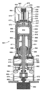
an axis into or out of the page. FIG. 7 shows a side view of the press 370,
wherein the
workpiece upon which the press would be brought to bear would move into and
out of the
press 370 along an axis going from side to side.
[0079] In both drawings, two pneumatically biasable linear actuators 320,
according to
the invention, and being preferentially biased for assisting extension of the
linear actuators
320, in the manner described above with regard to the first and second
exemplary
embodiments 100, 200 of the invention, each have a first end thereof mounted
to a first
structure, in the form of a base 374 and a second end thereof connected to a
second
structure, in the form of a bridge 372.
18
CA 02622810 2008-03-14
WO 2007/038426 PCT/US2006/037242
[0080] The bridge 372 has a surface or "platen" designed to hold an upper die
376. The
base 374 has a similar surface designed to hold a lower die 378. The press
shown uses two
linear actuators 320, but it should be understood that any number of actuators
320 could be
used depending on the size of the bridge 372 and the forces required.
Typically, there
would be an even number of linear actuators 320. Also, for the preferred
embodiment, a
roller screw and roller nut are used for the mechanical drive arrangement of
the linear
actuators 320, to make advantageous use of the longer life provided by this
type of drive
arrangement. However, in some applications, a ball screw assembly or some
other linear
actuator may be preferred.
[0081] FIG. 9 shows a fourth exemplary embodiment of the invention, in the
form of a
material forming machine, according to the invention, and more particularly,
in the form of
a die cushion arrangement 470, having two pneumatically biasable linear
actuators 420,
according to the invention, in the base of a press. hi an actual installation,
any number of
pneumatically biasable linear actuators 420, according to the invention, may
be utilized as
die cushion mechanisms in such an application. For purposes of simplicity of
illustration,
only two linear actuators 420 are shown in FIG. 9.
[0082] The linear actuators 420 each has a first end thereof mounted to a base
of the 474
of the press and a second, distal, end thereof coupled to a movable portion
475 of the lower
die 472. The upper die 478 is designed to mate with the fixed portion of a
lower die 472 to
form the workpiece 476. The workpiece 476 is interposed and clamped between
the upper
die 478 and the movable portions 475 of the lower die 472 throughout the
forming
operation. The die cushion mechanism 470 shown uses two linear actuators 420,
according
to the invention, but it should be understood that any number of actuators 420
could be used
depending on the number of movable portions 475 of the lower die 472, and the
clamping
forces required.
[0083] FIG. 9 shows the movable portions 475 of the lower die 472 as being
mounted
directly to the linear actuators 420, but in actual practice there are
frequently pins interposed
between the actuators 420 and the movable portions 475 of the lower die 472.
Also, for the
preferred embodiment, a roller screw and roller nut are used for the
mechanical drive
arrangement of the linear actuators 420, to make advantageous use of the
longer life
provided by this type of drive arrangement. However, in some applications, a
ball screw
assembly or some other linear actuator may be preferred.
19
CA 02622810 2008-03-14
WO 2007/038426 PCT/US2006/037242
[0084] In operation in a press, the upper die 478 is brought into contact with
the
workpiece 476. The linear actuator 420 may begin accelerating in a downward
direction
before the workpiece 476 contacts it. This "pre-acceleration" reduces the
impact force on
the workpiece 476, the dies 472, 478 and the press. As the upper die 478 is
lowered further,
the edges of the workpiece 476 are clamped between the upper die 478 and the
movable
portions 475 of the lower die 472. The clamping force exerted by the actuators
420 maybe
individually controlled during the forming cycle, to control the flow of the
material within
the dies 472, 478.
[0085] As the upper die 478 is lowered further still, the workpiece 476 is
formed
according to the clearance space between the die portions and the forces
applied. As a
result of the pressing operation, portions of the material of the workpiece
are caused to
stretch or flow within the clearance spaces. To properly control this flow of
material within
the dies 472, 478, the movable portions 475 of the lower die 472, must be
pressed upward
with the proper force by the linear actuators 420 as the upper die 478
continues its
downward motion. After the upper die 478 has reached its lowest point, the
motion of the
upper die 478 is reversed and it is returned to its initial position. The
linear actuators 420
may briefly continue the downward motion of the movable portions 475 of the
lower die
472 to separate the formed workpiece 476 from the upper die 478, before moving
the
movable portions 475 of the lower die 472 upward to their initial position.
[0086] It is desired to use the pneumatically biasable mechanical linear
actuators,
according to the invention, in a die press mechanism, according to the
invention, to thereby
minimize the amount of power required from the motor of the actuators 420 and
also for
reducing the load on the mechanical drive arrangement of the actuators 420. By
doing this,
the size of the motor and roller screw mechanism may be minimized, while
extending the
life of the drive arrangement of the actuators 420.
[0087] Throughout most of the press cycle the linear actuators 420 must exert
force in
an upward direction. The amount of pressurized gas in the cavities of the
pneumatic biasing
arrangement, the initial volume of the cavity, and any surge tanks can be set
to adjust the
average force and the variation of forces provided by the pneumatics in order
to reduce the
peak and average load on the screw mechanism, in a manner taking into account
factors
such as, but not limited to, the desired forces for forming the workpiece 476,
weights of
components, and acceleration of machine components during operation of the
die.
CA 02622810 2008-03-14
WO 2007/038426 PCT/US2006/037242
[0088] FIG. 10 is a simplified representation of a fifth exemplary embodiment
of the
invention in the form of a material forming machine, and more specifically, in
the form of a
mechanical press 520 incorporating a pneumatically biasable mechanical linear
actuator
apparatus 521 according to the present invention. The mechanical press 520
includes a
fixed base 522 on which is mounted a fixed platen 524 or bed for receiving a
workpiece or
stock material 526 to be processed by the mechanical press 520. The mechanical
press 520
further includes a movable platen 528 supported above the base 522 by the
pneumatically
biasable mechanical linear actuator apparatus 521, according to the present
invention, which
provides vertical movement of the platen 528 relative to the fixed platen 524.
[0089] Referring also to FIG. 11, in accordance with the invention, the
pneumatically
biasable mechanical linear actuator apparatus 521 for the mechanical press 520
includes a
plurality of pneumatically augmented linear actuators 531-534 which support
the movable
platen 528 in overlying relationship with the fixed platen 524 and provide
relative vertical
movement between the fixed and movable platens. In general, the linear
actuators 531-534,
of the fifth exemplary embodiment 520 of the invention, are functionally and
structurally
substantially identical to the linear actuator 200 of the second exemplary
embodiment of the
invention 200, described above in relation to the schematic illustrations of
FIGS. 2 and 3.
[0090] Preferably, one of the linear actuators 531-534 is provided near each
corner 536
of the mechanical press 520. The linear actuators 531-534 are oriented
vertically and have
their lower ends connected to the base 522 and their upper ends connected to
the movable
platen 528. The linear actuators 531-534 support the movable platen 528 in
overlying
relation with the fixed platen 524 and guide movement of the movable platen
528.
[0091] The pneumatically biased linear actuators 531-534, of the fifth
exemplary
embodiment of the invention, are described with reference to an application in
a straight
press machine of the type that is used to cut or form stock material 526 into
predetermined
length portions in a manner known in the art. In such application, the movable
platen 528
carries a die 540 that can include one or more cutting blades or material
forming tools.
Although the die 540 is shown mounted in the center of the movable platen 528,
the die can
be carried by the movable platen at any location that allows cutting or
forming of the stock
material 526 located on the fixed platen. The fixed platen 524 can be mounted
on a center
portion of the base 522 and is adapted to receive stock material 526 to be cut
or formed by
the die 540.
21
CA 02622810 2008-03-14
WO 2007/038426 PCT/US2006/037242
[0092] As was the case for the other exemplary embodiments of pneumatically
biased
mechanical linear actuators 108, 200 described hereinabove, the linear
actuators 531-534 of
the fifth exemplary embodiment of the invention can be used in material
forming machinery
other than the straight press machine 520, such as swing shear presses,
blanking shear
presses, forming presses, and in die cushions, for example.
[0093] The pneumatically augmented linear actuators 531-534 are identical, and
accordingly, only one linear actuator 531 is described in detail, with
reference to FIGS. 12-
16.
[0094] FIG. 14, is a vertical section view of the linear actuator 531 of FIG.
12 taken
along section line 14-14. In FIG. 14, the linear actuator 531 is shown at an
at rest or home
position which corresponds to the beginning of a down stroke.
[0095] The linear actuator 531 includes a actuator support structure 550,
including a
support pedestal 562, and a cylinder guide 564, supporting a drive
arrangement, in the form
of a roller screw mechanism 554, and a pneumatic biasing arrangement 556 which
is
connected at an upper end 622 thereof to movable bridge 558.
[0096] The cylinder guide 564 is attached at its lower end 560 to the top of
the pedestal
562. The pedestal 562 is generally rectangular in shape and includes four
sides 571-574
(FIG. 13) and a top 575. The sides 571-574 form a box-like structure, the
upper end of
which is closed by the top 575. The top 575 is generally rectangular in shape
and is secured
to the sides 571-574. The top 575 has a central aperture 576 in which is
mounted a thrust
bearing and seal assembly 583 for a screw member 593 of the roller screw
mechanism 554.
[0097] The lower end of the pedestal 562 terminates in an actuator mounting
plate 580
which is generally rectangular in shape. The actuator mounting plate 580 has a
central
aperture 582 that is aligned axially with the aperture 576 in the top 575. As
will be shown,
the screw member 593 is coupled to a drive motor 592, the shaft 595 of which
extends
through the aperture 582. The pedestal 562 contains an intermediate plate 584
including a
central aperture 585 that is aligned axially with apertures 576 and 582 and in
which is
mounted a further thrust bearing and seal assembly 606 for the screw member
593.
[0098] The cylinder guide 564 is a hollow tubular member that is supported on
and
fixed to the top 575 of the pedestal 562. The sidewall of the cylinder guide
564 has
22
CA 02622810 2008-03-14
WO 2007/038426 PCT/US2006/037242
diametrically opposed access openings 566 near the lower end 578 of the
cylinder guide
564.
[0099] Referring to FIGS. 10 and 11, the pedestal 552 is adapted for mounting
the linear
actuator 531 to the base 522 of the mechanical press 520. The upper end of the
linear
actuator 531 is adapted for attachment to the movable bridge 558, with the
movable bridge
558, in turn, being adapted for coupling the upper ends of the linear
actuators 531-534
collectively to the movable platen 528.
[00100] Reference is now made to FIGS. 14-16, which are vertical section views
(taken
alone lines 14-14, 15-15, and 16-16, as shown in FIG. 13, of the linear
actuator 531. FIG.
15 illustrates the condition of the linear actuator 531 in a fully extended
condition
corresponding to the beginning and end of a down stroke cycle of the movable
platen 528.
FIG. 16 illustrates the linear actuator 531 in a fully retracted condition
corresponding to the
lowermost movement of the movable platen 528 at approximately the mid-point of
a down
stroke cycle of the movable platen 528.
[00101] The roller screw mechanism 554, of the linear actuator 531, includes a
driving
member, in form of the screw member 593, and a driven member in the form of a
roller
screw nut member 594. The screw member 593 is rotatably driven directly by the
drive
shaft 595 of the drive motor 592. The roller screw nut member 594 is
operatively connected
to the screw member 593, and to a disc 609 at the lower end 578 of an axially
movable
cylinder 612 of the pneumatic biasing arrangement 556, such that rotary motion
of the
motor shaft 595 is converted into linear motion of the roller screw nut 594
and the axially
movable cylinder 612, in substantially the same manner as described above in
relation to the
linear actuators 108, 200 of the first and second exemplary embodiments 100,
200 of the
invention.
[00102] The screw member 593 is supported vertically within the cylinder guide
564.
The lower end 601 of the screw member 593 projects into the pedestal 562 and
is coupled to
the shaft 595 of the drive motor 592 through a coupling mechanism 600. The
upper end
602 of the screw member 593 is journalled in a recess 603 in a lower surface
604 of a fixed
piston 614 of a first cylinder structure, of the pneumatic biasing arrangement
556, formed
collectively by the fixed piston 614, a pair of guide posts 624, and the top
575 of the support
pedestal 562. The screw member 593 is supported intermediate the upper axial
end 602 and
the lower end 601 of the screw member 593 by the bearing and seal assemblies
583 and
606.
23
CA 02622810 2008-03-14
WO 2007/038426 PCT/US2006/037242
[00103] The drive motor 592 is mounted within the pedestal 552 with the shaft
595 of the
drive motor 592 extending through the aperture 582 in the actuator mounting
plate 580 into
the lower end of the pedestal 562, allowing the shaft 595 to be coupled to the
screw member
593 by the coupling mechanism 600.
[00104] The roller screw nut member 594 is enclosed within the cylinder guide
564. The
roller screw nut member 594 is threadedly engaged by the screw member 593 and
is
movable vertically relative to the cylinder guide 564 in response to rotation
of the screw
member 593 by the drive motor 592. The roller screw nut member 594 is coupled
by a disk
609 to an axially movable cylinder 612 of the pneumatic component 596. The
roller screw
nut member 594 is connected to the disk 609 by a plurality of screws 597 (FIG.
15). The
disk 609 is connected to the bottom of the axially movable cylinder 612 by a
plurality of
screws 599. The disk 609 and the axially movable cylinder 612 are translatable
vertically
up and down by the roller screw mechanism 554 to produce vertical
reciprocating motion
for the movable platen 528 as will be shown.
[00105] Referring to FIGS. 14-16, a pair of guide posts 624 are provided for
guiding the
disk 609 as it is moved vertically up and down. The disk 609 has through-bores
611
through which the guide posts 624 extend. The lower ends 613 of the guide
posts 624 are
mounted in the top 575 of the pedestal 562. The upper ends 615 of the guide
posts 624 are
secured in apertures 617 in the lower surface 619 of the fixed piston 614. The
guide posts
624 provide vertical guidance for the disk 609 and the axially movable
cylinder 612 carried
by the disk 609, and thus for the movable bridge 558 and the movable platen
528 which are
supported on the axially movable cylinder 612. The upper and lower ends of the
guide
posts 624 carry positive upper stops 623 (FIG. 15) and lower stops 625 (FIG.
15),
respectively, which define end of travel positions for the roller screw nut
member 594.
[00106] Referring to FIGS. 15 and 16, the pneumatic biasing arrangement 556
includes
the axially movable cylinder 612, the fixed piston 614 and a movable piston
616. The fixed
piston 614 is located within the axially movable cylinder 612 and is fixed to
and supported
by the screw member 593 to be located near the center portion of the axially
movable
cylinder 612. The fixed piston 614 closes the lower portion axially movable
cylinder 612
which is movable vertically relative to the fixed piston 614 and the cylinder
guide 564.
There is a sleeve bushing 627 interposed between the outer surface of the
axially movable
cylinder 612 and the inner surface of the cylinder guide 564. The concentric
axially
movable cylinder 612 and cylinder guide 564 provide a sliding joint and
function as guide
mechanism of the linear actuators 531-534 for maintaining parallelism for the
press 520.
24
CA 02622810 2008-03-14
WO 2007/038426 PCT/US2006/037242
[00107] The fixed piston 614 includes peripheral seals 626 that are located in
annular
grooves on the periphery of the fixed piston 614.
[00108] Referring to FIG. 16, the axially movable cylinder 612, the fixed
piston 614 and
the movable piston 616 form a closed, pressurized air chamber 610. As will be
shown,
pressurized air is introduced into the air chamber 610 to produce to offset
force for use in
returning the movable platen 528 to the home position during the up stroke of
an operating
cycle.
[00109] The pneumatic biasing arrangement 556 includes a fill tube 634 (FIG.
16) to
allow pressurized gas to be introduced into the pressurized chamber 610. The
fill tube 634
is normally sealed, in embodiments of the invention where a fixed precharge of
pressurized
gas is utilized, and is replaced with a connection to a control
arrangement(not shown) in
embodiments of the invention where the pressure in the cavity 610 is actively
controlled.
The fill tube 634 extends through an aperture 635 in a base 670 of the movable
bridge 558.
[00110] As shown in FIG. 12, the movable bridge 558 is a generally rectangular
structure including the base 670, four sides 671-674 and a top 675. The base
670 is secured
to the upper end of the axially movable cylinder 612 by a plurality of screws
676. The top
675 and at least opposite sides 672 and 674 include access openings, such as
access opening
678 in the top 675. The top 675 is adapted to be connected to the movable
platen 528.
[00111] The lower end 637 of the fill tube 634 is seated in a throughbore 638
of a volume
adjustment piston 616, described in more detail below, for communicating the
interior of the
fill tube 634 with the interior of the pressurized chamber 610. The fill port
636 defined by
the upper end of the fill tube 634 is located near the upper end 639 of the
movable bridge
558, providing access to the fill tube 634 through the access opening 678 for
introducing
pressurized gas into the pressurized air chamber 610.
[00112] In some embodiments of the invention, the cavity 610 contains an
amount of
pressurized gas sufficient to impose a unidirectional biasing force between
the roller screw
nut 594 and the screw member 593 of the roller screw mechanism 554. Two
parameters,
the pressure within the cavity 610 and the volume height of the cavity 610,
are adjusted to
provide the desired functionality for the pneumatic biasing arrangement 556.
The pressure
within the cavity 610 decreases over the length of the extension stroke of the
linear actuator
531. The volume of the cavity 610 determines how large the change in pressure
is from the
top to the bottom of a stroke.
CA 02622810 2008-03-14
WO 2007/038426 PCT/US2006/037242
[00113] The pneumatic biasing arrangement 556 is adjustable to allow the
mechanical
press 520 to be set up for processing workpieces of different sizes and to
provide different
processing functions (cutting, forming, etc.) as is known. The pressure and
volume height
are set at the values needed to cause the die 540 to properly interact with
the workpiece 526
during operating cycles of the mechanical press 520.
[00114] While in the exemplary embodiment 531, the size of the cavity 610 is
adjusted
using a hydraulic mechanism, the size of the cavity 610 can be adjusted in
other ways, such
as through the use of binary volume arrangement in which a plurality of
external are
selectively communicated with the interior of the cavity 610.
[00115] The pressure within the cavity 610 is selected to produce an upwardly
directed
force for causing the roller screw nut member 594 to be maintained in
engagement with the
screw member 593 at the same side of the screw thread of the screw actuator on
the
upstroke following reversal, thereby minimizing wear on the screw actuator.
Stated in
another way, the roller screw nut member 594 is pulled up due to the
unidirectional biasing
force generated by the pneumatic biasing arrangement 556, in the same manner
as described
above in relation to the actuator 200 of the second exemplary embodiment shown
in FIG. 4.
This results in reduction on force applied to the screw member 593 and roller
screw nut 594,
thereby extending the life of the roller screw mechanism 254. In addition,
this allows
reduction in the size of the screw member 593 and in the size of the drive
motor 592 and the
overall size of the pneumatically biasable mechanical linear actuator
apparatus 521.
[00116] Referring to FIGS. 14 and 15, the linear actuator 531 also includes a
pressure
cavity volume adjustment arrangement 598. The pressure cavity volume
adjustment
arrangement 598 includes a movable volume adjustment piston 616, and a volume
adjustment actuator, in the form of a hydraulic cylinder 640 and a hydraulic
piston 642
located within the hydraulic cylinder 640 for slidable movement along the
inner wall of the
hydraulic cylinder 640. The adjustment arrangement 598 is disposed in-line
with the
components of the pneumatic biasing arrangement 556, and with the screw member
593.
The adjustment arrangement 598 is enclosed within the movable bridge 558.
[00117] Referring to FIGS. 14 and 15, the hydraulic cylinder 640 includes a
tubular
member having a lower end 643 closed by a bottom member 644 and an upper end
645
closed by a top member 646. The bottom member 644 has an aperture 648 through
which
extends the rod end 650 of the hydraulic piston 642.
26
CA 02622810 2008-03-14
WO 2007/038426 PCT/US2006/037242
[00118] Referring to FIGS. 15 and 16, the hydraulic piston 640 has a piston
head 652
that is located within the hydraulic cylinder 640. The rod end 650 of the
hydraulic piston
642 extends through aligned apertures 648 and 656 in the bottom member 644 of
the
hydraulic cylinder 642 and in the base 670 of the movable bridge 558,
respectively. The
rod end 650 is connected to the movable piston 616 by a collar 660 (FIG. 15)
that traps an
enlarged end portion 662 of the piston rod 660. A post 664 indexes the movable
bridge 558
to the movable piston 616 of the pneumatic component 596.
[00119] The movable piston 616 is located within the axially movable cylinder
612, of
the pneumatic biasing arrangement 556, near the upper portion of the axially
movable
cylinder 612 for slidable movement along the inner wall of the axially movable
cylinder
612. The movable piston 616 closes the upper end of the axially movable
cylinder 612, and,
in combination with the fixed piston 614 and the portion of the inner surface
of the axially
movable cylinder 612 between the fixed piston 614 and the volume adjusting
piston 616,
defines the volume within the cavity 610 available for receiving pressurized
gas. The
volume adjusting piston 616 is movable relative to the axially movable
cylinder 612. The
axis of the movable piston 616 extends coaxially with the axis of the screw
member 593.
Peripheral seals 630 are located in annular grooves on the periphery of the
movable piston
616, for slidingly sealing the juncture of the piston 616 with the axially
movable cylinder
612.
[00120] The volume adjusting piston 616 is moved axially up or down (when the
actuator 531 is oriented as shown in 14 and 15) to provide an additional
mechanism for
conveniently adjusting the working volume of the cavity 610, and thereby
facilitate set up
and use of the linear actuator 321, of the fifth exemplary embodiment of the
invention,
when the operating load and/or operating force conditions, or the operating
stroke of the
actuator 531 change significantly.
[00121] As will be understood from a comparison of FIGS. 14 and 15, which both
show
the movable piston 616 spaced the same axial distance from the fixed piston
614, to thereby
provide the same volume in the cavity 610, the movable piston 616 of the
cavity volume
and minimum actuator length adjustment arrangement 598 may also be utilized
for
adjusting other operating parameters of the actuator 531, such as, but not
limited to, for
example: adjusting the relationship between the stroke length, and/or stoke
direction, of the
linear actuator 531, and the change in pressure within the cavity 610
resulting from the
stroke; adjusting the axial length of the linear actuator 531; setting maximum
and/or
27
CA 02622810 2008-03-14
WO 2007/038426 PCT/US2006/037242
minimum operating pressures for the pressurized gas within the cavity 610;
and/or, setting a
desired maximum or minimum magnitude of the unidirectional biasing force.
[00122] By operating the motor 592, to advance the roller screw nut 594 in a
manner
which keeps the axial spacing between movable piston 616 and the fixed piston
614
constant, as the extensible piston 642 of the adjustment arrangement 598 is
advanced into
the cavity 610, the fully retracted length of the linear actuator 531 can be
increased in an
amount equal to the distance that the piston 642 is advanced into the cavity
610, while
keeping the same operating stroke and biasing force. In this manner, the
length of the linear
actuator 200 may be selectively varied to allow use of die sets having
different vertical
heights, or for stroking in an opposite direction, for example, to thereby
facilitate and
expedite initial set-up and changing of set ups involving die sets having
different heights.
In FIG 14, the actuator 14 is set up for use in a downward stroke, from the
rest position
shown in FIG. 14, and in FIG. 15, the actuator 15 is set up for an up stroke,
from the rest
position shown in FIG. 15, with the volume of the cavity 610 being
substantially the same
in both set ups of the actuator 531.
[00123] Referring to FIG. 16, the linear actuator 531 includes a braking
mechanism 680
for holding the screw member 593. Preferably, the brakes are spring-applied,
pneumatic-
release brakes used to hold position and provide for emergency stopping. The
brakes 680
are located within the pedestal 562, in the exemplary embodiment of the linear
actuator 531,
but could be located elsewhere in other embodiments of the invention.. The
brakes 680, in
the exemplary embodiment 532, are caliper-type brakes including spring loaded
calipers
682 which engage a brake disk 684 that extends outward radially from the screw
member
593. The calipers 682 are actuated pneumatically to release the screw member
593 for
rotation by the drive motor 592.
[00124] The use of the terms "a" and "an" and "the" and similar referents in
the context
of describing the invention (especially in the context of the following
claims) is to be
construed to cover both the singular and the plural, unless otherwise
indicated herein or
clearly contradicted by context. The terms "comprising," "having,"
"including," and
"containing" are to be construed as open-ended terms (i.e., meaning
"including, but not
limited to,") unless otherwise noted. Recitation of ranges of values herein
are merely
intended to serve as a shorthand method of referring individually to each
separate value
falling within the range, unless otherwise indicated herein, and each separate
value is
incorporated into the specification as if it were individually recited herein.
All methods
described herein can be performed in any suitable order unless otherwise
indicated herein or
28
CA 02622810 2008-03-14
WO 2007/038426 PCT/US2006/037242
otherwise clearly contradicted by context. The use of any and all examples, or
exemplary
language (e.g., "such as") provided herein, is intended merely to better
illuminate the
invention and does not pose a limitation on the scope of the invention unless
otherwise
claimed. No language in the specification should be construed as indicating
any non-
claimed element as essential to the practice of the invention.
[00125] Preferred embodiments of this invention are described herein,
including the best
mode known to the inventors for carrying out the invention. Variations of
those preferred
embodiments may become apparent to those of ordinary skill in the art upon
reading the
foregoing description. The inventors expect skilled artisans to employ such
variations as
appropriate, and the inventors intend for the invention to be practiced
otherwise than as
specifically described herein. Accordingly, this invention includes all
modifications and
equivalents of the subject matter recited in the claims appended hereto as
permitted by
applicable law. Moreover, any combination of the above-described elements in
all possible
variations thereof is encompassed by the invention unless otherwise indicated
herein or
otherwise clearly contradicted by context.
29