Note: Descriptions are shown in the official language in which they were submitted.
CA 02623001 2008-03-18
WO 2007/034273 PCT/IB2006/002509
INVENTION TITLE
PROTECTIVE BARRIERS FOR SMALL DEVICES
DESCRIPTION
TECHNICAL FIELD
The present invention relates to the field of small devices, such as sensors,
actuators,
flow control devices, heaters, fluid injectors, among others, having
applications in harsh
environmental conditions. More particularly, the present invention is directed
to protective
barriers suitable for small devices with applications in harsh environmental
conditions, for
example, by immersion in oilfield fluids, such as high pressure-high
temperature downhole
fluids that are erosive and/or corrosive in nature.
BACKGROUND OF THE INVENTION
Development and extraction of hydrocarbon reserves involves the collection and
analysis of extensive data pertaining to fluids in the geological formations.
For example,
economic evaluations of hydrocarbon reserves in geological formations involve
a thorough
analysis of the formation fluids. Similarly, development and production
considerations, such
as methods of production, efficiency of recovery, and design of production
systems for the
hydrocarbon reserves, all depend upon accuracy in initial and continuing
analyses of the
nature and characteristics of reservoir hydrocarbon fluids. Formation analysis
and evaluation
requires constant measurements of formation fluids to acquire data with
respect to fluid
properties.
Determination of formation fluid characteristics, such as density, viscosity,
temperature, pressure, gas-oil ratio (GOR), bubble point, among others,
provides a way to
analyze the nature and characteristics of a reservoir formation. Measurements
of formation
fluid properties yield insight into geological formations, such as
permeability and flow
characteristics. The data also provide a way to assess the economic value of
hydrocarbon
reserves.
Typically, formation fluid samples are obtained during the exploration phase
of
oilfield development, and the thermophysical properties of the fluids are
determined at the
1
CA 02623001 2008-03-18
WO 2007/034273 PCT/IB2006/002509
surface. However, often it is necessary andJor desirable to determine certain
reservoir fluid
properties, such as density and viscosity of crude oil or brine, at the
pressure and temperature
of a hydrocarbon reservoir. Although the pressure and temperature of fluid
samples at the
surface can be adjusted to the conditions in the reservoir, it is sometimes
difficult to obtain a
fluid sample at the surface that closely replicates the downhole formation
fluid in chemical
composition.
It has been found that variations tend to occur in the extracted fluid samples
due to
volatility of lighter hydrocarbons, deposition of solids, contamination by
drilling fluids, and so
on. Moreover, it is very expensive to extract downhole fluid samples from a
borehole, and to
maintain and handle the extracted fluid samples at the surface under downhole
pressure and
temperature conditions. It is advantageous, therefore, to acquire and transmit
fluid properties
data downhole for the data to be analyzed at the surface, thereby
significantly reducing the
time and costs associated with hydrocarbon reservoir analysis and evaluation.
Answer products, such as analyses based on downhole fluid analysis, that
relate to
reservoir production and optimization are typically based on analyzing
extremely small
samples of downhole fluid, i.e., by volume relatively less than 10-9 of the
hydrocarbon
reserves in a typical geological formation. Moreover, the composition and
characteristics of
formation fluids in a reservoir are subject to change as the hydrocarbon
reserves are developed
and extracted. Therefore, it is advantageous to regularly monitor formation
fluid properties by
taking frequent downhole measurements of formation fluids throughout the
exploration and
production phases of an oilfield.
The oilfield fluids typically handled in the oil exploration and production
industries
are an extremely harsh operating environment in comparison with the customary
conditions
where small measuring and data collection devices, such as microchip sensors,
are used. For
example, typical downhole fluid conditions in producing hydrocarbon reservoirs
include
downhole temperatures from 50 to 175 degrees Celsius or more, downhole
pressures from 100
to 2,000 bar, densities in the range 500 to 1300 kg m 3, and viscosities from
0.1 to 1000 mPa s.
As a result of their chemical and compositional properties, oilfield fluids
tend to be
erosive and corrosive in nature. Due to the difficult environments in which
oilfield equipment
is deployed, the equipment must be capable of withstanding severe shoclc and
corrosion due to
the possibility of corrosive fluid constituents, such as H2S and C a, and
solid particulates,
such as sand, being present in flowing formation fluids. Reference is made to
J. A. C.
Humphrey, Fundanaental of Fluid Motion in Erosion by Solid Particle Iinpact,
Int. J. Heat and
2
CA 02623001 2008-03-18
WO 2007/034273 PCT/IB2006/002509
Fluid Flow, Volume 11, #3, September 3, 1990, and references therein, for a
discussion on
erosion that is caused by solid particulates, such as sand, in fluids.
Furthermore, hydrocarbon reservoir fluids tend to be complex and may contain
chemical components ranging from asphaltenes and waxes to methane. The
composition of
hydrocarbon fluids makes deposition of waxy materials on downhole tools a
distinct
possibility, which often is a cause of fouling of the tools.
SUMMARY OF THE INVENTION
In consequence of the background discussed above, and other factors that are
known
in the field of oilfield exploration and production, applicants recognized a
need for robust
small devices capable of withstanding extreme exposure to oilfield fluids in
applications under
downhole conditions.
Applicants further recognized that in the oil exploration and production
industries
small devices have potential applications in numerous areas relating to the
evaluation and
development of hydrocarbon fluids, if the small devices were suitably
protected against
adverse downhole-type conditions.
Applicants noted that at the present time there is no generally known
protective
coating or barrier suitable for protecting small devices in high pressure-high
temperature harsh
environments of oil industry applications.
Applicants discovered surface coatings and protective barriers that would
produce a
robust device suitable for applications in harsh environments, such as by
immersion in
formation fluids at or near downhole conditions.
Applicants recognized that their discovery would provide an integrated
solution to
various related failure modes of small devices in harsh downhole applications.
In this,
protective barriers of the present invention provide a solution to failure of
the devices due to
corrosion as well as erosion of electrical insulation, such as by downhole
fluids. Applicants
recognized that the present invention also offers a solution to failure of
small devices due to
the rapid flow of larger particulates or thread-like strands that could foul
the behavior of a
microelectromechanical systems (MEMS) type device. For example, such a failure
mode
would be advantageously addressed by placing suitable flow diversion elements,
such as in
one preferred embodiment of the invention small baffle-type devices, on one or
both sides of
the MEMS-type device to divert the potentially damaging materials away from
the MEMS-
type device.
3
CA 02623001 2008-03-18
WO 2007/034273 PCT/IB2006/002509
The present invention includes a range of small devices, such as devices based
on
MEMS technology. The devices may be used for applications such as analyzing or
measuring
thermophysical properties of fluids, for example, oilfield reservoir fluids,
or for flow and rate
control of fluids under difficult, harsh conditions, such as downhole or in a
pipeline. As used
herein, the phrase "thermophysical properties" of fluids describes, for a
phase of fixed
chemical composition, fluid properties that change with changes in pressure
and temperature,
such as density and viscosity. For example, CRC Handbook of Chemistry and
Physics, CRC
Press, 81St Ed., 2000, pages 6-16, provides a list of thermophysical
properties of fluids where
the tabulated properties include density, energy, enthalpy, entropy, isochoric
heat capacity,
isobaric heat capacity, speed of sound, viscosity, thermal conductivity, and
dielectric constant.
Moreover, calculated thermophysical properties include compressibility factor,
specific
volume, density, enthalpy, internal energy, entropy, isochoric and isobaric
specific heat, speed
of sound, Joule-Thomson coefficient, adiabatic exponent, volume expansion
coefficient,
thermal pressure coefficient, saturated vapor pressure, heat of vaporization,
dynamic and
kinematic viscosity, thermal conductivity, temperature conductivity and
Prandtl number.
Applicants recognized that problems associated with placing MEMS-based devices
without suitable protection in contact with fluids at or near downhole
conditions stemmed
from corrosion and/or erosion effects on the devices by the fluids.
Applicants further discovered that robustness issues with respect to MEMS
devices
in harsh applications could be overcome by a surprisingly thin protective
coating, which
advantageously would not interfere with or impede operational effectiveness of
the MEMS
devices.
Applicants recognized that protection of MEMS-based devices that measure
density
and viscosity of hydrocarbon fluids would be particularly effective, though
protective barriers
of the invention would serve to protect any small device exposed to downhole
fluids or other
similar erosive and/or corrosive fluid-based environmental conditions.
Applicants further recognized that the present invention would protect MEMS-
based
devices from chemical-based corrosion that readily occurs in high pressure-
high temperature
(HPHT) saltwater found downhole. As used herein, the term "HPHT" refers to
downhole
temperatures in excess of ambient temperature, typically in the order of 100
degrees Celsius
and more, downhole pressures typically from 100 to 2,000 bar, densities in the
range 300 to
1300 kg m 3, and viscosities from 0.1 to 1000 mPa s. In this, it is a feature
of applicants'
discovery that the protective coatings of the invention are surprisingly
efficacious in the
atypical conditions found in downhole fluids. It is applicants' unique
understanding and
4
CA 02623001 2008-03-18
WO 2007/034273 PCT/IB2006/002509
realization of the conditions that exist in downhole fluids, in relation to
placing MEMS-based
devices in such adverse conditions, which led applicants to the protective
barriers of the
present invention.
Applicants also recognized that the protective barriers of the present
invention would
protect against erosion of unprotected MEMS devices by particulates suspended
in rapidly
flowing fluids, such as sand particulates in reservoir fluids.
Applicants further recognized that the protective barriers of the present
invention
would protect against fouling of small devices by drop-out materials from
reservoir fluids.
In accordance with the invention, a downhole fluid analysis system includes a
small
device adapted for downhole use to measure a property of a flowing fluid in
contact with the
device and a protective barrier for protecting the device against the fluid,
such as, against
erosion and corrosion by the fluid. The protective barrier may comprise a
coating on the
device and, in one aspect of the invention, the coating may be selected from
the group
consisting of tantalum, tungsten, titanium, silicon, boron, aluminum,
chromium, and their the
oxides, carbides and nitrides. In one preferred embodiment of the invention,
the coating may
be selected from the group consisting of silicon carbide, boron nitride, boron
carbide, tungsten
carbide, chromiunl nitride, titanium nitride, silicon nitride, titanium
carbide, tantalum carbide,
tungsten, titanium, aluminum nitride, tantalum oxide, silicon carbide and
titanium oxide.
In one embodiment of the invention, the coating comprises titanium nitride. In
another embodiment of the invention, the coating comprises tantalum oxide. In
yet another
embodiment of the invention, the coating comprises an anti-adhesion layer as
an outer layer of
the coating on the device. In yet another embodiment of the invention, the
protective barrier
comprises two or more layers of coating on the device.
In another embodiment of the invention, the protective barrier comprises a
first layer
of tantalum oxide and a second layer of titanium nitride; the tantalum oxide
layer protects
against corrosion and the titanium nitride layer protects against erosion with
the titanium
nitride layer being over the tantalum oxide layer. An anti-adhesion layer may
be deposited
over the titanium nitride layer as an outer layer on the device. In yet
another embodiment of
the invention, the protective barrier comprises a baffle device for deflecting
particulate laden
flow away from the device. At least one coating may be provided on the device.
In another embodiment of the invention, a tool adapted to be movable through a
borehole that traverses an earth formation comprises means for extracting a
fluid from the
earth fonnation into the tool and a small device arranged to be in fluid
contact with the fluid in
5
CA 02623001 2008-03-18
WO 2007/034273 PCT/IB2006/002509
the tool to determine a fluid property. A protective barrier is associated
with the small device
for shielding the device against corrosion and erosion by the fluid.
In another aspect of the invention, a device having high temperature, high
pressure
applications comprises a portion for exposure to high temperature, high
pressure subterranean
fluids that are at least one of erosive and corrosive in nature, and a
protective barrier
associated with the downhole device for protecting the exposed portion of the
device against at
least one of erosion and corrosion by the fluids. In one preferred embodiment
of the invention,
the downhole device comprises a MEMS sensor.
In yet another aspect of the invention, a method of downhole fluid analysis
comprises
establishing fluid communication between a downhole device, adapted for
measuring fluid
properties under high temperature and high pressure conditions, and
subterranean formation
fluids in a borehole. The method of the invention provides at least one
protective barrier
associated with the downhole device for protecting the downhole device against
erosion and
corrosion by the formation fluids.
Additional advantages and novel features of the invention will be set forth in
the
description which follows or may be learned by those skilled in the art
through reading the
materials herein or practicing the invention. The advantages of the invention
may be achieved
through the means recited in the attached claims.
BRIEF DESCRIPTION OF THE DRAWINGS
The accompanying drawings illustrate preferred embodiments of the present
invention and are a part of the specification. Together with the following
description, the
drawings demonstrate and explain principles of the present invention.
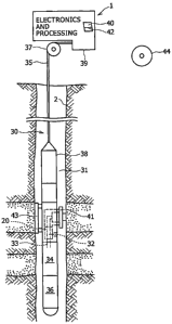
Figure 1 is a schematic representation of one embodiment of a system for
downhole
analysis of formation fluids according to the present invention with an
exemplary tool string
deployed in a wellbore.
Figure 2(A) shows a schematic representation in cross-section of silicon oxide
encapsulating metal (M) lines on a silicon chip; Figure 2(B) is a schematic
representation in
cross-section of tantalum oxide encapsulating the silicon chip depicted in
Figure 2(A), in one
embodiment of the present invention; Figure 2(C) is a plan view of a portion
of a silicon chip,
as schematically represented in Figure 2(A), after immersion into saltwater,
showing that
silicon oxide barrier is not sufficient protection as evidenced by vertical
broken wires and
variation of color, the color variation being indicative of corrosion; and
Figure 2(D) is a plan
6
CA 02623001 2008-03-18
WO 2007/034273 PCT/IB2006/002509
view of a similar portion of another silicon chip, as schematically
represented in Figure 2 (B),
after immersion into saltwater, showing that a protective barrier of tantalum
oxide protects
aluminum wires from corrosion by saltwater since the wires (vertical lines)
are still intact.
Figures 3(A) and 3(B) are plan views of portions of silicon chips, shown
schematically in Figures 2(A) and 2(B), respectively, after exposure to
downhole fluids during
a Gulf of Mexico job using Schlumberger's Modular Formation Dynamics Tester
(MDT).
Figure 3(A) shows that the chip protected with a coating of silicon oxide is
disabled due to
corrosion of the metal wires. Figure 3(B) shows that the chip protected with a
protective
coating of tantalum oxide is not attacked by downhole fluids.
Figures 4(A) and 4(B) are plan views of the exact same regions of a silicon
chip,
shown schematically in Figure 2(B); before and after exposure to downhole
fluids during a
Gulf of Mexico job using Schlumberger's Modular Formation Dynamics Tester
(MDT).
These two images allow for direct comparison of the metal wires before and
after immersion
into downhole fluids.
Figure 5(A) is a schematic depiction in cross-section of a protective barrier
according
to another embodiment of the present invention encapsulating an exemplary
silicon chip and
Figure 5(B) schematically depicts in cross-section yet another embodiment of a
protective
barrier according to the present invention.
Figure 6 is a schematic depiction of yet another embodiment of a protective
barrier
according to the present invention
Figure 7 illustrates one exemplary embodiment of a MEMS fluid sensor with a
protective barrier according to one embodiment of the present invention.
Throughout the drawings, identical reference numbers indicate similar, but not
necessarily identical elements. While the invention is susceptible to various
modifications and
alternative forms, specific embodiments have been shown by way of example in
the drawings
and will be described in detail herein. However, it should be understood that
the invention is
not intended to be limited to the particular forms disclosed. Rather, the
invention is to cover
all modifications, equivalents and alternatives falling within the scope of
the invention as
defined by the appended claims.
DETAILED DESCRIPTION OF THE PREFERRED EMBODIMENTS
Illustrative embodiments and aspects of the invention are described below. In
the
interest of clarity, not all features of an actual implementation are
described in the
7
CA 02623001 2008-03-18
WO 2007/034273 PCT/IB2006/002509
specification. It will of course be appreciated that in the development of any
such actual
embodiment, numerous implementation-specific decisions must be made to achieve
the
developers' specific goals, such as compliance with system-related and
business-related
constraints, that will vary from one implementation to another. Moreover, it
will be
appreciated that such development effort might be complex and time-consuming,
but would
nevertheless be a routine undertaking for those of ordinary skill in the art
having benefit of the
disclosure herein.
Microfabricated and microelectromechanical (MEMS) devices are increasingly
used
in applications that require immersion into a variety of gases and corrosive
fluids, including
acids, bases, and brine. The applications range from biological, such as
chemical analysis of
blood samples with lab-on-a-chip implementations, to materials-based, such as
conibinatorial
examination of various alloys in weathering tests. MEMS-based devices are also
being
developed to measure acceleration, resistivity, or the physical properties of
fluids, as described
in Schlumberger-Doll Research's (SDR) published United States patent
application: Pub. No.:
2002/0194906, the entire contents of which are incorporated herein by
reference. MEMS and
other sensors for high pressure-high temperature environments are also
described in U.S.
Patent Application No.: 11/230,793, titled Apparatus for pownhole Fluids
Analysis Utilizing
Micro Electrical Mechanical Systems (MEMS) or Other Sensors, with inventors
Chikenji et al.,
filed concurrently herewith and having common ownership, the entire contents
of which are
incorporated herein by reference.
In many cases, a measurement is performed which necessitates application of an
electric field or voltage on a MEMS sensor immersed in a fluid. In such cases,
saltwater is a
special challenge to electronic circuits as the resulting electric fields can
induce
electrochemical effects; even when coated with an insulator that inhibits
corrosion. Such
electrochemical effects can quickly (-l second) destroy the sensor and lead to
the production
of explosive, physically damaging, or chemically corrosive gases. Furthermore,
erosion of the
sensor by impact of flowing suspensions of particulates can be highly
damaging.
There are methods known for protecting conventional tools and instruments
exposed
to corrosive fluids found downhole, but the thickness of the protective
coatings is typically
greater than can be tolerated by a small device, such as a MEMS-based sensor.
These coatings,
were they to be applied to a typical MEMS device, would cause either complete
failure of the
sensor or, at a minimum, a highly detrimental effect to device performance.
Moreover, the
coatings typically contain micrometer-scale grains, the size of which is set
by heat treatment
and forming. This grain size is often larger than the relevant dimensions of
microfabricated
8
CA 02623001 2008-03-18
WO 2007/034273 PCT/IB2006/002509
chips, making their use impossible or impractical at best as a protective
layer for MEMS
devices.
Furthermore, many of the methods of application of such coatings are
incompatible
with MEMS microfabrication methods due to high temperatures or electroplating
baths. As a
part of the invention, applicants recognized that only those materials whose
grain sizes as well
as fabrication and application processes are compatible with microfabrication
would be
acceptable as protective barriers for MEMS-type devices.
Due to a growing interest in MEMS-based sensors and measurement devices, there
has been work performed on protective materials that are suitable for
microfabricated sensors.
It is known that humidity and moisture are "killers" of such sensors, and
protective coatings
for microfabricated devices have been evaluated. In their invention,
applicants recognized that
deficiencies such as pinholes and cracks in sputtered films would eliminate
such films as a
possibility for high pressure-high temperature (HPHT) oil services
applications. Such cracks
act as pores and allow penetration by high conductivity saltwater, destroying
the device.
Other known coatings are aggressively attacked by saltwater and have not
performed well in
tests that use the coatings as protective layers for oilfield applications. In
this, applicants have
found that HPHT saltwater is surprisingly effective at corroding a variety of
materials that are
thought of as completely compatible with water, such as glass, and that few
materials can
withstand this environment.
There are conventional coatings that are used to protect tools from erosion
caused by
wear and tear. However, usage of the conventional protective coatings has been
limited to
protecting macroscopic tools; it is believed that no use has been made of a
hard coating to
protect microfabricated products from erosion caused, for example, by the flow
of suspended
particles such as sand, in ultra corrosive and/or erosive environments found
downhole.
In the difficult environment of HPHT oil services applications, it is highly
desirable
to have small devices with one or more protective barrier so that the devices
can operate
effectively in complicated and harsh operating environments. Applicants found
no
commercially available device that exists today to satisfy these requirements.
Figure 1 is an exemplary embodiment of one system 30 for downhole analysis and
sampling of formation fluids according to the present invention, for example,
while a service
vehicle or other surface facility 1 is situated at a wellsite. In Figure 1, a
borehole system 30
includes a borehole tool string 31, which may be used for testing earth
formations and
analyzing the composition of fluids from a formation. The borehole too131
typically is
suspended in a borehole 2 from the lower end of a multiconductor logging cable
or wireline 35
9
CA 02623001 2008-03-18
WO 2007/034273 PCT/IB2006/002509
spooled on a winch 37 at the formation surface. The logging cable 35 typically
is electrically
coupled to a surface electrical control system 39 having appropriate
electronics and processing
systems for the borehole tool 31.
The borehole tool 31 includes an elongated body 3 8 encasing a variety of
electronic
components and modules, which are schematically represented in Figure 1, for
providing
necessary and desirable functionality to the borehole tool string 31. A
selectively extendible
fluid admitting assembly 41 and a selectively extendible tool-anchoring member
43 are
respectively arranged on opposite sides of the elongated body 38. Fluid
admitting assembly
41 is operable for selectively sealing off or isolating selected portions of a
borehole wal12
such that pressure or fluid communication with adjacent earth formation is
established. The
fluid admitting assembly 41 may be a single probe module and/or a packer
module. Examples
of borehole tools are disclosed in U.S. Patent Nos. 3,780,575, 3,859,851 and
4,860,581, the
contents of which are incorporated herein by reference in their entirety.
One or more fluid analysis modules 32 may be provided in the tool body 38.
Fluids
obtained from a formation and/or borehole flow through a flowline 33, via the
fluid analysis
module or modules 32, and then may be discharged through a port of a pumpout
module (not
shown). Alternatively, formation fluids in the flowline 33 may be directed to
one or more
fluid collecting chambers 34 and 36, such as 1, 2 3/4, or 6 gallon (1 gallon =
0.0038 m) sample
chambers and/or six 450 cm3 multi-sample modules, for receiving and retaining
the fluids
obtained from the formation for transportation to the surface.
The fluid admitting assemblies, one or more fluid analysis modules, the flow
path
and the collecting chambers, and other operational elements of the borehole
tool string 31, are
controlled by electrical control systems, such as the surface electrical
control system 39.
Preferably, the electrical control system 39, and other control systems
situated in the tool body
38, for example, include processor capability for characterization of
formation fluids in the
tool 31.
The system 30 of the present invention, in its various embodiments, preferably
includes a control processor 40 operatively connected with the borehole tool
string 31. The
control processor 40 is depicted in Figure 1 as an element of the electrical
control system 39.
Preferably, processing and control methods are embodied in a computer program
that runs in
the processor 401ocated, for example, in the control system 39. In operation,
the program is
coupled to receive data, for example, from the fluid analysis module 32, via
the wireline cable
35, and to transmit control signals to operative elements of the borehole tool
string 31.
CA 02623001 2008-03-18
WO 2007/034273 PCT/IB2006/002509
The computer program may be stored on a computer usable storage medium 42
associated with the processor 40, or may be stored on an external computer
usable storage
medium 44 and electronically coupled to processor 40 for use as needed. The
storage mediutn
44 may be any one or more of presently known storage media, such as a magnetic
disk fitting
into a disk drive, or an optically readable CD-ROM, or a readable device of
any other kind,
including a remote storage device coupled over a switched telecommunication
link, or future
storage media suitable for the purposes and objectives described herein.
In preferred embodiments of the present invention, small devices 20 with
protective
barriers of the invention may be embodied in one or more fluid analysis
modules of
Schlumberger's formation tester tool, the Modular Formation Dynamics Tester
(MDT). The
present invention advantageously provides a formation tester tool, such as the
MDT, with
enhanced functionality for the downhole characterization of formation fluids
and the collection
of formation fluid samples. In this, the formation tester tool may
advantageously be used for
sampling formation fluids in conjunction with downhole characterization of the
formation
fluids.
Applicants have addressed the shortcomings in the prior art by suitable
protective
barriers that provide advantageous and surprising results when used with small
devices, in
particular, small measuring and data collection tools that are intended for
immersion in
formation fluids at or near downhole conditions. In this, it is the
applicants' discovery that
one or more suitable barrier may be used with a device depending on the nature
and
characteristics of the fluid of interest and the parameters to be measured.
For example, if the
fluid of interest is corrosive, but not erosive, one or more suitable
protective barrier may be
selected based on that prior knowledge. Similarly, if the fluid has suspended,
flowing
particulates, but not corrosive elements, a coating and/or baffle-type
protective barrier could
be selected accordingly. Such selections of suitable protective barriers are
possible, without
undue experimentation, by a person having skill in the art, with knowledge of
the composition
and nature of the fluid or fluids of interest, in light of the present
invention.
Protective barriers of the present invention include, but are not limited to,
coatings
comprising elements such as tantalum, tungsten, titanium, silicon, boron,
aluminum,
chromium, among others, and their compounds such as oxides, carbides and
nitrides. For
example, the present invention contemplates one or more coatings of silicon
carbide, boron
nitride, boron carbide, tungsten carbide, chromium nitride, titanium nitride,
silicon nitride,
titanium carbide, tantalum carbide, tungsten, titanium, aluminum nitride,
tantalum oxide,
silicon carbide, titanium oxide. It is noted here that stoichiometry data for
the referenced
11
CA 02623001 2008-03-18
WO 2007/034273 PCT/IB2006/002509
coatings have not been provided since stoichiometrical parameters of the
coatings are not
considered necessary features that define the coatings. Rather, suitability of
any coating is
determined by the utility of the coating for the protective purposes of the
present invention.
Protective barriers in accordance with the present invention also may be
provided by
insertion of baffles in a flowline for the fluids. Moreover, small devices
that are exposed to
fluid borne particulates may be protected by providing streamline, steps,
ramps and/or wells
by modifying the flowline for the fluids in the vicinity of the small devices.
In tests performed concerning corrosion prevention with tantalum oxide, it has
been
found that tantalum oxide is easily applied to MEMS chips, adheres well to the
sublayer, does
not interfere with the chips' resonance behavior, and does not degrade upon
immersion into
HPHT salt water. Moreover, tantalum oxide films can easily be patterned by
plasma etching,
a technique known to those skilled in the art of microfabrication.
Laboratory experiments have demonstrated that MEMS sensors protected with a
coating of tantalum oxide show a higher lifetime when exposed to corrosive
fluids than
MEMS sensors that are not protected with a tantalum oxide coating. Figure 2(A)
is a
schematic representation in cross-section of silicon oxide encapsulating metal
(M) lines on a
silicon chip. Figure 2(B) depicts an embodiment of the invention having
tantalum oxide as a
protective barrier encapsulating the silicon chip in Figure 2(A). Figure 2(C)
is a plan view of
a portion of a silicon chip, schematically represented in Figure 2(A), after
immersion into
saltwater. Figure 2(D) is a plan view of a portion of another silicon chip
according to one
embodiment of the invention with a tantalum oxide protective barrier,
schematically
represented in Figure 2(B), after immersion into saltwater.
Referring to Figure 2(A), a silicon chip 10 with aluminum wires 12 was
protected
with approximately 1 micrometer of silicon oxide coating 14. In Figure 2(B),
the silicon chip
10 in Figure 2(A) is shown with the aluminum wires 12 having approximately 1
micrometer
coating of amorphous tantalum oxide 16 on top of the silicon oxide coating 14
according to
the present invention. After four days of being exposed to 150 C 1.5 molar
saltwater, with
pressure below 10 atmospheres, the aluminum wires of the silicon oxide coated
sample
(Figure 2(A)) corroded and the chip was unable to function. Figure 2(C) is a
micrograph of a
portion of the silicon chip depicted in Figure 2(A) showing corrosion and
damage to the
aluminum wires of the chip. In contrast, wires protected by tantalum oxide
(Figure 2(B))
exposed to the same conditions were intact and functionally unaffected by
saltwater fluid, as
shown in the micrograph of Figure 2(D).
12
CA 02623001 2008-03-18
WO 2007/034273 PCT/IB2006/002509
In Figure 2(C), the wide vertical lines, broken in certain regions, correspond
to the
aluminum wires (M). There is a narrow gap between each of the wires that
isolates each one
from the others. Figure 2(C) shows that the silicon oxide is not sufficient
protection as
evidenced by the broken wires and variation of color; the color variation
being indicative of
corrosion that has attacked or removed the aluminum wire in the darker
regions.
As in Figure 2(C), Figure 2(D) shows vertical wires with narrow gaps in
between.
The small dark spots on the wires result from the grain structure of aluminum
and not from
corrosion. The uniform color of the wires and their unbrolcen structure
indicate that corrosion
has been inliibited by the protective coating. Hence, Figure 2(D) shows that
the tantalum
oxide protects aluminum wires from corrosion. The thin horizontal line in the
bottom of
Figure 2(D) is an artifact of fabrication and unrelated to the testing. It is
noted that the net
thickness of the coatings in Figure 2(D) is twice that of Figure 2(C),
however, the laboratory
experience of the applicants is that this comparatively small increase in film
thickness does not
greatly augment a coating's ability to protect a chip in the manner shown
here. Rather the
corrosion inhibition demonstrated by the tantalum oxide in Figure 2(D) is
ascribed to be
chemical in origin.
Figures 3(A) and 3(B) are micrographs of portions of silicon chips, shown
schematically in Figures 2(A) and 2(B), respectively, after exposure to
downhole fluids during
a job in the Gulf of Mexico using Schlumberger's Modular Formation Dynamics
Tester
(MDT). The MDT, and hence the chips, were exposed to maximum temperature of
239
degrees Fahrenheit and pressure of 10343 psi. Figure 3(A) shows that the chip
protected with
only a coating of silicon oxide (note Figure 2(A)) is disabled due to
corrosion of the metal
wires. Figure 3(B) shows that the chip protected with a coating of tantalum
oxide according to
the invention (note Figure 2(B)) is not attacked after immersion into downhole
fluids at a Gulf
of Mexico wellsite. This qualifies as the erosive and/or corrosive HPHT
environment
described earlier.
The metal wires on the silicon chips appear as vertical or horizontal lines in
Figures
3(A) and 3(B). The chip in Figure 3(A) has been protected by a layer of
silicon oxide and the
metal wires have been attacked by the downhole fluids. In the circled region
of Figure 3(A),
the color of the wire has changed to pink, indicative of corrosion. This
indicator of corrosion
is consistent with applicants' accelerated corrosion tests in the laboratory.
The metal wires of
the chip shown in Figure 3(B), while covered with particulates and mud (darker
matter), show
no evidence of corrosion as they have been protected by a layer of tantalum
oxide.
13
CA 02623001 2008-03-18
WO 2007/034273 PCT/IB2006/002509
Figures 4(A) and 4(B) are plan views of portions of silicon chips, shown
schematically in Figure 2(B), before and after exposure to downhole fluids
during a Gulf of
Mexico job using Schlumberger's Modular Formation Dynamics Tester (MDT).
Figure 4(B)
shows that the chip protected with a protective coating of tantalum oxide
(shown in Figures
4(A) and 4(B)) is not attacked after immersion into downhole fluids. The chip
shown in
Figure 4(B) was immersed into downhole fluids at a maximum depth of 9867 feet
and
maximum temperature of 195 degrees Fahrenheit for 10 hours. The water based
mud had a
pH of 5.4. This qualifies as the erosive and/or corrosive HPHT environment
described earlier.
As these two micrographs correspond to the exact same locations on the silicon
chip before
and after the job, they afford a direct comparison of the chip before and
after exposure to the
downhole fluids. The unbroken metal lines and uniform color indicate that
corrosion was
successfully inhibited. The dark spots that are randomly distributed are most
likely mud or
contamination that was not removed before the micrograph was obtained. -
Figure 5(A) is a schematic depiction of another embodiment of the invention.
In
Figure 5(A), a chip 10, as depicted in Figure 2(A), is encapsulated with
titanium nitride 18 as a
protective coating according to the present invention.
Applicants discovered that for HPHT, highly corrosive and/or erosive
conditions,
which are found downhole at certain wellsites, a particularly advantageous
protective barrier is
achieved by a multi-layer, composite coating having at least two back-to-back
coatings. In
one preferred embodiment of the protective barrier, one layer is provided as a
corrosion barrier
and a second layer is provided as a hardness coating. Advantageously, the
hardness coating
encapsulates the corrosion barrier.
Figure 5(B) shows schematically a composite protective barrier, according to
one
preferred embodiment of the present invention, encapsulating an exemplary
silicon chip 10
with metal wires 12. In one preferred embodiment depicted in Figure 5(B),
tantalum oxide
functions as a corrosion barrier 16 and titanium nitride as a hardness coating
18. The
embodiment of Figure 5(B) is particularly advantageous as a composite barrier
for protecting
small devices in the extremely harsh, particulate-laden fluid environments of
the type
described herein.
Advantageously, coatings of the invention are applied so that thickness of an
individual coating, and combined thickness of a composite protective barrier,
preferably are in
the range from about 0.01 micrometer to about 100 micrometers. More
preferably,
thicknesses of individual coatings and combined layers are in the range from
about 0.1
micrometer to about 10 micrometers. In this, it is noted that coating
thickness is important
14
CA 02623001 2008-03-18
WO 2007/034273 PCT/IB2006/002509
from the point of suitability with respect to functionality of a device having
the coating, i.e.,
the applied coating should not impede or prevent operation of the device.
Moreover, the
applied coating or combination of coatings may be varied in thickness
depending on the
operating conditions for the device, as previously discussed above in
connection with selecting
a suitable coating or combination of coatings for the device.
Applicants recognize that a single-layer coating would provide beneficial
results, in
particular, if the coating thickness were sufficient to provide an adequate
measure of
protection against fluid corrosion and/or erosion. It is also recognized that
a single coating
would suffice if the small device with the coating were to have an operational
life for a pre-
determined period of time and be considered as expendable after the time-based
period of use.
Applicants, however, identified desirable, unexpected results in using a multi-
layer
coating in particularly harsh, difficult environments found in certain
wellbores. In such
environniental applications, it is believed that a single-layer coating alone
would suffice only
to protect a microfabricated device for a limited period of time, i.e., no
more than about less
than 1 second to about several minutes, if immersed into a HPHT flowing,
particulate-laden,
corrosive fluid. For example, tantalunl oxide might not have sufficient
hardness to protect the
device from erosion by flow of suspended particles. Rather, a multi-layer
coating is preferred,
advantageously with an outer layer of titanium nitride and an inner layer of
tantalum oxide.
Embodiments of the present invention, such as those described above, may be
made
by a variety of methods.
Sputtering of tantalum oxide targets by a sputtering agent, such as a driven
plasma of
argon or oxygen. The sputtering agent is used to bombard a pressure ceramic
target of
tantalum oxide, which then sprays a beam of blasted tantalum oxide onto the
substrate.
Alternatively, a tantalum target can be sputtered with an oxygen plasma,
thereby reacting and
creating a tantalum oxide plume.
Tantalum oxide or tantalum is evaporated with an electron beam in an oxygen
environment to provide a coating on the substrate.
Thin tantalum films are oxidized to produce coating of tantalum oxide on the
substrate. Firstly a tantalum film is deposited, by sputtering or thermal
evaporation. One
implementation is to convert the metal to an oxide by immersion into an
electrolytic fluid,
such as acetic acid, and applying a voltage between the film and a solution. A
second
implementation is to convert the film to an oxide by application of an oxygen
plasma,
subjected to radiofrequency or other power source. A third implementation is
to convert the
CA 02623001 2008-03-18
WO 2007/034273 PCT/IB2006/002509
metal film thermally, that is, by heating it up to 800 degrees Centigrade in
an oxygen rich
environment.
Chemical vapor deposition is a preferred method that is also used in the
microchip
industry. Chemical vapor deposition includes low pressure chemical vapor
deposition
(LPCVD) and plasma enhanced chemical vapor deposition (PECVD). In this
implementation,
the coating is more conformal; that is, its coating follows surface structures
to form a better
seal, especially those on steps. However, in order to form the gaseous
organometallic
precursors, corrosive or explosive gases must be handled, for which there is
standard handling
equipment available now. Though some carbon and hydrogen may be incorporated
into the
final film, perhaps changing the electrical properties, it has been found not
to affect the
intended use of the coating.
Titanium nitride coatings may be provided by chemical or plasma vapor
deposition
(CVD or PVD) and sputtering. In this, reference is made here to Cunha et al.,
Thin Solid
Films, 317, (1998), at page 351 for a further description of the noted
methods. PVD is a
preferred method for coating titanium nitride as it provides a better
conformal coating, but
alternative coating methods are also contemplated in practicing the invention.
It is to be understood that while applicants have chosen the above particular
parameters, such as materials, methods, other parameters and processing steps
may be used to
manufacture protective barriers according to the present invention. Thus, the
present
invention is not intended to be limited to the small devices and coating
methods described
herein.
Fouling of tool components, such as microfabricated sensors, optical windows,
among others, exposed to downhole fluids is a concern when using the tools.
Fouling can be
caused by, for example, asphaltene or wax drop out. Such a thickening coating
during use of a
sensor alters the sensor's measurements to the point of being useless.
Applicants discovered
that a protective coating, deposited from a fluorine-based plasma, is
compatible with MEMS-
focused microfabrication processes and would prevent fouling due to its low
surface-energy.
Accordingly, in yet another embodiment of the invention, a fluorinated anti-
adhesion layer 19
(note Figure 5(B)) may be applied to a small device, such as a sensor, as a
coating to prevent
fouling of the small device by adhesion of drop-out materials from downhole
fluids in contact
with the device.
MEMS devices that are protected by the present invention may be used, for
example,
by the oil industry, to accurately and efficiently measure fluid properties,
both downhole while
immersed in formation fluids and at the surface in a laboratory environment,
under conditions
16
CA 02623001 2008-03-18
WO 2007/034273 PCT/IB2006/002509
which would quickly malce unprotected MEMS devices inoperative. In this, MEMS-
based
devices having one or more protective barriers according to the present
invention may be
embedded in a well or in a formation. The devices also may be incorporated
into downhole
sampling and fluid analysis tools, such as Schlumberger's Modular Formation
Dynamics
Tester (MDT), or into a sample bottle designed to hold formation fluid samples
under
downhole conditions.
Figure 6 is a schematic representation of a MEMS-based sensor with protective
barriers according to another embodiment of the present invention. Figure 6
shows a small
device 10, for example, a vibrating plate MEMS sensor, immersed in a fluid
(arrows in Figure
6 represent fluid flow around the device 10) flowing through a flowline of a
downhole tool,
such as the MDT. Since particulate laden fluid flowing over the device 10
would damage the
fragile device 10, protective plates or baffles 13 may be provided in the
flowline to
substantially divert the particulate laden flow around the device 10, as
indicated by the arrows
in Figure 6. In this, configurations of the baffles 13 may be based on the
nature and
configuration of the device 10 as well as operational considerations, such as
fluid flow rates
and nature of the particulate materials of the fluids flowing in the flowline.
The device 10 may be separated from the protective barrier or barriers 13 by a
minimum value. In this, each barrier 13 is separated from the device 10 so
that negligible
systematic error, or one that can be compensated for, is introduced into the
measurements
obtained from the device 10. This value will depend upon the specific property
measured.
For example, in the embodiment of Figure 6, the minimum separation value
equals the largest
characteristic dimension of the object, such as the width of the vibrating
plate. Preferably, the
thickness and length of a baffle are at least equal to the same dimensions for
a device which
the baffle protects. In addition to particulate materials, the flowing media
might have threads
or filament-like contaminants. It is intended that the baffles would protect
the small devices
from damage by such contaminants and these considerations also determine the
dimensions of
the baffles.
Figure 6 represents schematically one preferred embodiment of the present
invention.
The protective barriers that are depicted in Figure 6 may be modified so that
only one baffle
13 is provided before the device 10, i.e., upstream to the device 10, so that
the particulate
laden fluid flows over the baffle 13 before crossing the device 10. Moreover,
the baffle 13
need not be rectangular in shape as depicted in Figure 6, but may be a wedge
shaped baffle
with the sharp edge toward the flowing fluid; a baffle with a profile similar
to an aerofoil; a
triangular baffle with the apex of the triangle toward the MEMS; and/or a
semicircular baffle.
17
CA 02623001 2008-03-18
WO 2007/034273 PCT/IB2006/002509
Furthermore, additional barriers for protecting the small devices may include
modifications to
the flowline of the tool in the vicinity of the small devices, for example, by
providing
streamlines, steps, ramps and/or wells in the flowline to suitably divert
particulate laden fluids
in the flowline about the small devices.
The present invention has applicability to a range of small devices, in
particular, but
without limitation, a range of electro-mechanical devices. These devices tend
to have a
characteristic dimension less than about 500 micrometers, such as the width,
thickness or
length. Preferably, the devices tend to have a characteristic dimension in the
range of about 10
to about 250 micrometers. In particular, the present invention contemplates
protecting devices
having a thickness of about 50 micrometers and less. The devices are adapted
for applications
in harsh and complicated fluid environments, such as analyzing and measuring
thermophysical
properties of oilfield fluids under downhole conditions and during
transportation of erosive
and/or corrosive fluids, such as for refining. In one preferred embodiment of
the present
invention, the coatings described herein also may be used to protect any
vibrating element
directly exposed to downhole fluids. In particular, vibrating element devices
having sub-
micrometer amplitude, which are used to measure thermophysical properties of
fluids, such as
viscosity and density, in the field of downhole fluid analysis may be
protected by the present
invention.
Typically, the electro-mechanical devices described herein are micro-machined
out
of a substrate material and are fabricated using technologies that have been
developed to
produce electronic integrated circuit (IC) devices at low cost and in large
quantities, i.e., batch
fabrication. Devices of this type are typically referred to as
microelectromechanical systems
(MEMS) devices, and applicants believe the present invention provides the
first protective
barriers for such small devices having applications in oilfield fluid
environments, in particular,
downhole fluid environments.
Figure 7 illustrate an exemplary sensor embodiment that may be protected with
one
or more protective barriers of the present invention. In this, only the parts
of the sensor that
are to be coated are shown in Figure 7 and other parts have been omitted.
Figure 7 is a schematic representation of a flexural plate-type MEMS-based
sensor
20 having a planar member 24 with a flexural plate 22 attached thereto along
one side 23.
Fluid in contact with sensor 20 surrounds the flexural plate 22 and fills area
21 so that, when
activated, the flexural plate 22 vibrates and causes the fluid to move. Cross-
hatching in Figure
7 represents a protective barrier for the sensor 20 to protect the sensor
against adverse fluid
conditions. Furthermore, as described above in connection with Figure -6,
protective barriers
18
CA 02623001 2008-03-18
WO 2007/034273 PCT/IB2006/002509
such as baffles and other similar devices may be provided to protect the
sensor 20 from fluid
damage. Though the protective barrier in Figure 7 is shown as covering most of
the sensor 20,
the protective barrier may be selectively applied to cover the areas of the
sensor that are at risk
of being damaged by fluid contact.
In downhole tests conducted by applicants, it was found that a MEMS device
protected with a protective coating of the present invention was able to
withstand the high
flow rates of fluids in a downhole tool. In this, applicants surprisingly
found that particulate
materials in the fluids did not immediately destroy the MEMS device protected
in accordance
with the present invention. Unexpectedly, a comparatively thin coating
according to the
present invention was found to be surprisingly effective in protecting a MEMS
device.
Applicants found that saltwater in pa'rticular rapidly corrodes a MEMS device
when
operated, for example, when voltages are applied to the device in saltwater
environments. In
somewhat less than one minute a MEMS-based sensor is corroded by saltwater.
Unexpectedly,
applicants discovered that protective coatings of the present invention,
having thicknesses, for
example,.in the range of about 1 micrometer, could extend the life of the MEMS-
type device
almost 10000 times longer, for example, up to 20 hours. In this, the efficacy
of the coatings of
the present invention in extending the life of MEMS devices was a surprising
and unexpected
result obtained by applicants.
Moreover, applicants found that the protective barriers of the present
invention were
unexpectedly effective in protecting MEMS-based devices from chemical based
corrosion,
which tends to occur more quickly even for coated chips at the surfaces of the
chip where a
wire or strain gauge is at a greater height than the rest of the chip, for
example, at a step or a
sidewall of the chip device. The protective coatings of the present invention
were found to be
surprisingly effective in spite of the almost certain existence of pin-holes
in the coated
MEMS-based devices tested by applicants.
The preceding description has been presented only to illustrate and describe
the
invention and some examples of its implementation. It is not intended to be
exhaustive or to
limit the invention to any precise form disclosed. Many modifications and
variations are
possible in light of the above teaching.
The preferred aspects were chosen and described in order to best explain
principles
of the invention and its practical applications. The preceding description is
intended to enable
others skilled in the art to best utilize the invention in various embodiments
and aspects and
with various modifications as are suited to the particular use contemplated.
It is intended that
the scope of the invention be defined by the following claims.
19