Note: Descriptions are shown in the official language in which they were submitted.
CA 02623006 2008-03-18
WO 2007/047484 PCT/US2006/040177
APPARATUS FOR THE UNINTERRUPTIBLE FILTERING OF GAS
CROSS REFERENCE TO RELATED APPLICATION
[0001] This application hereby claims the benefit of
commonly owned pending U.S. Provisional Patent Application
Ser. No. 60/726,154, for Uninterruptible Evaporate Removal,
Storage, and Transfer Device, filed October 13, 2005.
BACKGROUND OF THE INVENTION
[0002] The present invention relates to the field of
evaporated liquid removers. More specifically, the
invention relates to a device for eliminating moisture in an
environment.
[0003] Devices such as dehumidifiers, air-conditioners,
desiccant-based devices, and the like remove excess moisture
from the air. Known devices for this purpose are
electrically powered dehumidifiers that remove evaporated
liquid from a gas by passing the liquid-laden gas over a
cooled surface where the evaporated liquid condenses,
thereby reducing the evaporated liquid content of the gas.
[0004] A problem with conventional evaporated liquid
removers is their reliance upon utility-provided electrical
power (via an electrical grid) or fueled generators to
function. As a result, conventional evaporated liquid
removers cease to operate following a disaster (e.g.,
hurricane or electrical storm) that damages a community's
utility infrastructure. Failure of the conventional
evaporated liquid removers results in the growth.of mold
(e.g., black mold) within a building or dwelling. The mold
damages or destroys wall surfaces, rugs, floors, textile-
1
CA 02623006 2008-03-18
WO 2007/047484 PCT/US2006/040177
based furniture coverings, and similar articles contained
within a building or dwelling. Further, the growth of mold
presents a health hazard to occupants of the building or
dwelling and to repair crews during reconstruction efforts.
[0005] An additional problem with known devices is their
inability to operate on low-voltage, low-current power
sources such as small photovoltaic cells or other small
nature-powered electrical generating devices.
[0006] Although known devices may be suitable for the
particular purpose to which they address, they are not
suitable for uninterruptible reduction, removal, storage,
and transfer of an evaporated liquid. In this respect, the
apparatus for the uninterruptible filtering of a volume of
gas according to the present invention substantially departs
from the conventional concepts and designs provided in the
prior art. In so doing, the present invention is ideally
suited for 'situations requiring the uninterrupted reduction,
removal, storage, and transfer of an evaporated liquid
contained in a gas.
' SUMMARY OF THE INVENTION
[0007] In one aspect the invention is an apparatus for
filtering a volume of gas. The apparatus contains a hollow
vessel having at least one inlet to and at least one outlet
from an internal cavity defined by the vessel. A filter or
filtering media, such as a desiccant or other adsorbing or
absorbing material, is provided to perform the filtering. A
flow controlling device, such as an electric fan or
impeller, is mounted within or adjacent to an end of the
vessel to regulate the flow of gas through the system.
2
CA 02623006 2008-03-18
WO 2007/047484 PCT/US2006/040177
[0008] In another aspect, the invention is a method for
filtering a volume of gas using a filtering device. Gas is
drawn into the device through at least one inlet and passes
over a filter media, which separates the undesired suspended
matter from the gas. The filtered gas is then discharged
through at least one outlet.
[0009] The foregoing, as well as other objectives and
advantages of the invention and the manner in which the same
are accomplished, is further discussed within the following
detailed description and its accompanying drawings.
BRIEF DESCRIPTION OF THE DRAWINGS
[0010] The present invention now will be described more
fully hereinafter with reference to the accompanying
drawings, in which some, but not all embodiments of the
invention are shown. Indeed, this invention may be embodied
in many different forms and should not be construed as
limited to the embodiments set forth herein; rather, these
embodiments are provided so that this disclosure will
satisfy applicable legal requirements.
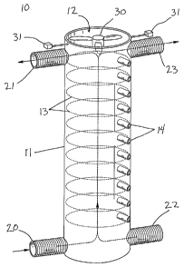
[0011] Figure 1 is a perspective view of one embodiment of
the apparatus having a cylindrical vessel, four channels
that may serve as inlets or outlets, an electric fan, two
sensors, and a plurality of openings for accessing the
filter media.
[0012] Figure 2a is a cross-sectional side view of one
embodiment of the apparatus having an electric fan connected
to a power source and two sensors, and four solenoid-
3
CA 02623006 2008-03-18
WO 2007/047484 PCT/US2006/040177
controlled valves regulating the flow paths into and out of
the inlets and outlets.
[0013] Figure 2b is a perspective view of one embodiment of
the filter media for the apparatus depicting an exploded
view of a series of stackable disc filters on a central hub.
[0014] Figure 2c is a perspective view of another embodiment
of the filter media in the form of a circular tray capable
of holding a filtering substance.
[0015] Figure 3 is a view of one embodiment of the apparatus
incorporated into a building wall and having a rectangular
shape and a plurality of openings for accessing the filter
media contained within the apparatus.
DETAILED DESCRIPTION
[0016] The invention relates to an apparatus for the
uninterruptible filtering of a volume of gas. More
specifically, the invention relates to an apparatus for
removing excess moisture from the air using a filtering
device powered independently of electricity provided by a
utility via an electrical (or power) grid.
[0017] The terminology used herein is for the purpose of
describing particular embodiments only and is not intended
to be limiting of the invention. As used herein, the term
"and/or" includes any and all combinations of one or more of
the associated listed items. As used herein, the singular
forms "a," "an," and "the" are intended to include the
plural forms as well as the singular forms, unless the
context clearly indicates otherwise. It will be further
understood that the terms "comprises" and/or "comprising,"
4
CA 02623006 2008-03-18
WO 2007/047484 PCT/US2006/040177
when used in this specification, specify the presence of
stated features, integers, steps, operations, elements,
and/or components, but do not preclude the presence or
addition of one or more other features, integers, steps,
operations, elements, components, and/or groups thereof.
[0018] Unless otherwise defined, all terms (including
technical and scientific terms) used herein have the same
meaning as commonly understood by one having ordinary skill
in the art to which this invention belongs. It will be
further understood that terms, such as those defined in
commonly used dictionaries, should be interpreted as having
a meaning that is consistent with their meaning in the
context of the relevant art and the present disclosure and
will not be-interpreted in'an idealized or overly formal
sense unless expressly so defined herein.
[0019] In describing the invention, it will be understood
that a number of techniques and steps are disclosed. Each
of these has individual benefits and each can also be used
in conjunction with one or more, or in some cases all, of
the other disclosed techniques. Accordingly, for the sake
of clarity, this description will refrain from repeating
every possible combination of the individual steps in an
unnecessary fashion. Nevertheless,"the specification and
claims should be read with the understanding that such
combinations are entirely within the scope of the invention
and the claims.
[0020] For ease of discussion, the apparatus will be
described with reference to the removal of excess evaporated
liquid from the air within an environment. Those having
ordinary skill in the art will recognize that the invention
is applicable to any application where undesirable matter is
CA 02623006 2008-03-18
WO 2007/047484 PCT/US2006/040177
suspended in a gas (e.g., moisture or contaminants). The
use of the term "filter" or "filtering" is intended to
include any device or process that separates distinct
components from within a gas and is not intended to indicate
only'the removal of solid particulate by means of a screen
or strainer.
[0021] The concept of a component or element of the
invention being "between" two other components does not
necessarily imply that the three components are contiguous
(i.e., in intimate contact). Rather, as used herein, the
concept of one component being between two other components
is meant to describe the relative positions of the
components within the assembly structure, respectively.
[0022] Those skilled in the art will also appreciate that
the term "adjacent" refers to two or more, for example,
components or elements that have a common border or are in
close proximity to one another. Nevertheless, it will be
understood that adjacent may or may not imply contact, but
always implies the absence of anything of the same kind in
between.
[0023] In one aspect, the invention is an apparatus 10 for
filtering a volume of gas. The filtering of a volume of gas
is accomplished through a combination of elements in this
apparatus 10. Referring to Figure 1, the invention provides
a hollow vessel 11 defining an internal cavity 12 for
containing various elements of the apparatus 10. The
internal cavity 12 is accessible via a first inlet 20 and a
first outlet 21. The first inlet 20 and first outlet 21
provide a flow path into and out of the internal cavity 12
of the hollow vessel 11. The hollow vessel 11 may be formed
in any number of shapes, such as a cylinder, a cube, a
6
CA 02623006 2008-03-18
WO 2007/047484 PCT/US2006/040177
sphere, a rectangular prism, or any other shape for a
container known in the art (see Figures 1 and 3).
[0024] With reference to Figures 2b and 2c, the invention
further provides filter media 13 for separating components
of the volume of gas brought into the internal cavity 12 of
the hollow vessel 11. In one embodiment, the filter media
13 may include one or more stackable disc filters 16
positioned on a central hub 17. In another embodiment,
filter media 13 may be contained within a circular tray 18
capable of holding a filtering substance. The filter media
13 may include desiccants, conditioners, modifiers,
ionization devices, acids, salts, other liquid adsorbing or
absorbing materials or chemicals, or any combination of the
above. The process of separating components accomplished by
the filter media 13 may encompass removing unwanted
suspended particles, viruses, or bacteria from within a
gaseous mixture. That said, the embodiment discussed in
detail serves to remove excess evaporated liquid from a
volume of air.
[0025] Further provided is a flow control device 30 as
depicted in Figure 1 for advancing the volume of gas across
the filter media 13. Preferably, the flow control device 30
requires little to no electric power such that it can
operate in the event of a power failure in an electrical
grid, meaning the failure of electricity provided to a
region, city, community, or building by a central utility or
fuel-fired generator. The apparatus 10 may thus remain
operational in emergency situations (e.g., post-natural
disaster). Examples of such a flow control device 30
include small electric fans or impellers requiring a low-
voltage power source. The flow control device 30 may be
7
CA 02623006 2008-03-18
WO 2007/047484 PCT/US2006/040177
positioned within the hollow vessel 11 and adjacent to the
inlet 20 or outlet 21 of the hollow vessel, or any position
facilitating the effective drawing of the volume of gas into
the internal cavity 12 through the inlet 20, across the
filter media 13 contained within the hollow vessel 11, and
then out through the outlet.
[0026] Referring to Figure 1, the apparatus 10 may also
include at least one sensor 31 configured to identify the
presence or characteristics of a gaseous component, a vapor
component, a liquid component, a solid component, a
particulate component, a bacterial component, a viral
component, and combinations thereof in the environment to be
filtered. In one embodiment, the sensor 31 detects the
relative humidity of the air in an environment. The
measurements taken by the sensor 31 may then be output by a
transmitter to a controller. The signal transmitted from
the sensor 31 to the,controller may be a simple "on or off"
value to indicate the presence of a component or a specific
measurement of a component. Alternatively, the signal may
provide the precise value of a measurement.
[0027] The controller used in conjunction with the sensor 31
receives the signal from the sensor. The controller in turn
is connected to the flow control device 30 and is capable of
regulating the operation of the flow control device. The
way in which the controller regulates the operation of the
flow control device 30 depends upon the signal received from
the sensor 31 and the kind of controller used.
[0028] For example, if the sensor 31 produces a simple "on
or off" signal, or if the controller is only capable of "on
or off" commands, the controller may turn the flow control
device 30 on or off in response to the conditions measured
8
CA 02623006 2008-03-18
WO 2007/047484 PCT/US2006/040177
by the sensor. Alternatively, if the sensor 31 provides a
signal containing precise values, and the controller and
flow control device 30 are capable of variable outputs, the
controller may regulate the intensity of output from the
flow control device 30 based upon the difference between the
values measured by the sensor 31 and the target value. In
other words, the controller may turn the flow control device
30 to maximum power if the sensor 31 detects an excessive
amount of the undesirable component in the environment
measured.
[0029] Further, if there are multiple environments involved
in the operation of the apparatus 10, such as an interior
and exterior of a building, additional sensors 31 may be
provided to likewise measure the composition or
characteristics of the additional environments. The
additional sensors 31 also communicate via a transmitter
with the controller to control the operation of the flow
control device 30. For example, one sensor 31 may measure
the relative humidity of the air in the interior of a
building, and a second sensor 31 may measure the humidity of
the ambient air outside of the building. The controller may
then regulate the operation of a fan to draw outside air
through the apparatus 10 to provide fresh air having a pre-
selected humidity as depicted in Figure 3.
[0030] In one embodiment, the signal transmitted from the
sensor 31 is a measurement of the relative humidity of the
air in a selected environment (e.g., first or*second
environment). The controller regulates the operation of the
flow control device 30 to maintain the relative humidity of
the environment within a predetermined range of values. For
instance, it may be desirable to keep the humidity of the
9
CA 02623006 2008-03-18
WO 2007/047484 PCT/US2006/040177
air in a building below 60o to prevent the growth of mold
and other fungi capable of destroying articles contained
within the building (e.g., carpet, furniture, curtains, and
foodstuffs). .
[0031] The apparatus 10 may also provide a power supply 33
to provide electric power to the powered components of the
apparatus 10, such as the flow control device 30, the
controller, and the sensors 31.. Because the apparatus 10 is
intended to operate uninterrupted, even in the event of a
natural disaster or other loss of utility power, the power
supply 33 will preferably operate independently of utility-
provided electricity or fueled generators. Even with this
limitation, there exist a variety of devices that may serve
as the power supply 33 for this apparatus 10. For example,
a photovoltaic cell may provide the necessary power to drive
the flow control device 30, the controller, and the sensors
31. Other power supply devices suitable for this use
include batteries and other small nature-powered electrical
generating devices.
[0032] Referring to Figure 2a, the apparatus 10 may also
include a number of flow regulators 34, 35, such as valves,
serving to control the flow of the volume of gas into or out
of the inlets and outlets of the hollow vessel 11. An inlet
flow regulator 34 may control the flow of gas into the first
inlet 20. A outlet flow regulator 35 may control the flow
of the filtered gas out of the first outlet 21.
[0033] In one embodiment, the inlet and outlet flow
regulators 34, 35 are solenoid-operated valves as
illustrated in Figure 2a. Further, because one embodiment
of the apparatus 10 is intended to operate in the absence of
utility-provided electric power, the solenoid-operated
CA 02623006 2008-03-18
WO 2007/047484 PCT/US2006/040177
valves may operate with a low-voltage power source as
disclosed above. With that limitation, magnets may be
employed to maintain the position of the valves 34 and 35
(e.g., secured to an internal surface of the hollow vessel
11). In such an arrangement, the positioning of the valves
34, 35 does not require a constant draw of power. in this
embodiment, the invention may provide a capacitor in
communication with the valves 34, 35 to provide a sufficient
burst of current to overcome the magnetic bond securing the
valves 34, 35 to the hollow vessel 11 and operate the
solenoid. Of course, this example is but one possible flow
regulator that may be used. Many other magnetic, hydraulic,
air, memory metal, or other means of opening and closing
channels, ducts, or passageways may be employed to
accomplish this function.
[0034] The apparatus 10 may additionally provide a second
inlet 22 for conveying a volume of gas into the hollow
vessel 11 (see Figures 1, 2a, and 3). The second inlet 22
may convey gas from a different environment than that from
which the first inlet 20 draws. For example, the first
inlet 20 may draw air from a space within the interior of a
building (e.g., a first environment) while the second inlet
22 may draw air from the exterior of the building (e.g., a
second environment) as depicted in Figure 3. Alternatively,
the second inlet 22 may draw from a different location
within the same environment. An example of this alternative
would be a situation wherein the first inlet 20 and second
inlet 22 draw air from opposite sides of a single room in a
building. These two situations are described only as
examples of the variety of applications requiring multiple
inlets.
11
CA 02623006 2008-03-18
WO 2007/047484 PCT/US2006/040177
[0035] ,Likewise, a second outlet 23 may be provided for
conveying a volume of filtered gas out of the hollow vessel
11. The second outlet 23 may convey the filtered gas to an
environment other than that into which the first outlet 21
discharges. The second outlet 23 thus provides an optional
avenue for discharging the volume of filtered gas. For
example, moisture laden air drawn by the apparatus 10 from a
space contained within a building (i.e., a first
environment) and then filtered may either be discharged
through the first outlet 21 back into the same space or
through the second outlet 23 to the exterior of the building
(i.e., a second environment).
[0036] In a similar configuration with respect to the first
inlet 20 and first outlet 21, flow regulators 34, 35 may
control the flow of gas into and out of the hollow vessel 11
through the second inlet 22 and second outlet 23,
respectively. Depending on the intended operation of the
apparatus 10, the additional inlets and outlets may
correspond with separate flow regulators or, or they may
,
share the flow regulators 34, 35 corresponding with the
first inlet 20 and first outlet 21.
[0037] For example, in the embodiment shown in Figure 2a,
the first inlet 20 and first outlet 21 are positioned on
opposite sides of the hollow vessel 11 from the second inlet
22 and second outlet 23, respectively. The solenoid-
operated valves serving as the flow regulators 34, 35 in
this embodiment are positioned with one valve 34 in between
the pair of inlets 20, 22and another valve 35 in between the
pair of outlets 21, 23. The valve 34 associated with the
inlets is configured to open the first inlet 20 when the
second inlet 22 is closed, and vice versa. Likewise, the
12
CA 02623006 2008-03-18
WO 2007/047484 PCT/US2006/040177
valve 35 associated with the outlets is configured to open
the first outlet 21 when the second outlet 23 is closed, and
vice versa. As a result, this configuration allows for the
volume of gas-filtered or unfiltered-to be conveyed from
either the first inlet 20 or the second inlet 22, and
exhausted through either the first outlet 21 or the second
outlet 23.
[0038] Referring to Figures 1 and 3, the apparatus 10 may
also include at least one opening 14 in the hollow vessel 11
that permits access to the filter media 13 for purposes of
filling, emptying, or otherwise maintaining the filter media
13. The openings 14 may include a series of small openings
as shown in Figures 1 and 3. This arrangement permits solid
materials (e.g., desiccant beads) or liquids used as the
filter media 13 to be pumped into and evacuated from the
hollow vessel 11. Provided in conjunction with these
openings 14 may be a cover 15 serving to protect the filter
media 13 when not being maintained. One example is a cover
strip having protrusions on one side that correspondingly
engage the openings 14.
[0039] With specific reference to the figures depicting
various embodiments of the invention, Figure 1 illustrates
one embodiment of the apparatus 10 having a cylindrical
hollow vessel 11, a first inlet 20, a second inlet 22, a
first outlet 21, a second outlet 23, a fan that serves as
the flow control device 30, two sensors 31 that may measure
the composition or characteristics of the environment on
either side of the hollow vessel 11, and a small opening 14
associated with each layer of the filter media 13 that
allows for maintenance access.
13
CA 02623006 2008-03-18
WO 2007/047484 PCT/US2006/040177
[0040] In this embodiment, a volume of gas is supplied to
either or both of the first inlet 20 and second inlet 22 at
the bottom of the hollow vessel 11. The volume of gas is
then advanced upwards through the filter media 13 by means
of the fan serving as the flow control device 30. Once the
volume of air passes through each layer of the filter media
13 and reaches the top of the hollow vessel 11, it is then
exhausted through either or both of the first outlet 21 or
the second outlet 23.
[0041] Figure 2a depicts another embodiment of the apparatus
having an electric fan connected to a power supply 33 and
two sensors 31, andrfour solenoid-controlled valves serving
as flow regulators 34, 35 for the first inlet 20, second
inlet 22, first outlet 21, and second outlet 23. In this
embodiment, the solenoid-controlled valve 34 at a lower end
of the apparatus 10 allows flow to be conveyed into the
hollow vessel 11 either through the first inlet 20 or the
second inlet 22. Likewise, the solenoid-controlled valve 35
at an upper end of the apparatus 10 allows flow to be
exhausted from the hollow vessel 11 either through the first
outlet 21 or the second outlet 23. In this embodiment,
connections from the power supply 33 to the flow regulators
34, 35, sensors 31, and flow control device 30 are shown.
The embodiment of the apparatus 10 configured as shown in
Figure 2a allows for gas to be conveyed through the first
inlet 20, where it is drawn through the layers of filter
media 13 by the flow control device 30, and then the gas is
exhausted through the first outlet 21.
[0042] Figure 2b illustrates a perspective view of one
embodiment of the filter media 13 for the apparatus 10. In
this figure, a series of disposable stackable disc filters
14
CA 02623006 2008-03-18
WO 2007/047484 PCT/US2006/040177
16 are positioned on a central hub 17. In this embodiment,
the filter media 13 and hub 17 may be removed and replaced
via an opening 14 provided at the top or side of the hollow
vessel 11.
[0043] Figure 2c depicts another embodiment of the filter
media 13 in the form of a circular tray 18 capable of
holding a filtering substance. In this embodiment, the
filter media 13 may be likewise be removed and replaced via
an opening 14 provided at the top or side of the hollow
vessel 11.
[0044] Figure 3 illustrates another embodiment of the
apparatus 10 incorporated into the corner of a building,
wherein the hollow vessel 11 is rectangular shape and
includes a plurality of openings 14 for accessing (i.e.,
removing and replacing) the filter media 13. The openings
14 are protected by a cover 15 for use at times when the
filter media 13 is not being maintained.
[0045] In another aspect, the invention is a method of
filtering a volume of gas using an apparatus 10 as described
above. In a first step, the method includes providing an
apparatus 10 that includes a hollow vessel 11 defining an
internal cavity 12, a first inlet 20, and a first outlet 21.
The hollow vessel 11 for use in this method also contains
filter media 13 for separating components of a volume of gas
conveyed into the hollow vessel 11. The hollow vessel 11
further contains a flow control device 30 for directing the
volume of gas through the hollow vessel 11 and over the
filter media 13.
[0046] In a next step, the method includes directing a
volume of gas into the first inlet 20 of the hollow vessel
CA 02623006 2008-03-18
WO 2007/047484 PCT/US2006/040177
11 and across the filter media 13. Upon arrival at the
filter media 13, the method includes separating components
of the volume of gas to form a filtered volume of gas. As
this invention is intended to operate continuously as
needed, even in the event of a major disaster or other loss
of utility-provided power, it is important that the step of
separating continues uninterrupted until a pre-selected
condition is achieved. The pre-selected condition may, for
example, be the reduction of the relative humidity in the
air within an environment sought to be filtered, the
elimination of a contaminant or otherwise undesirable
suspended inatter in a volume of gas, or any other measurable
characteristic or composition of a volume of gas.
[0047] The method further provides an apparatus 10 that
facilitates communication between a first environment and a
second environment. As configured in this one embodiment,
the apparatus 10 draws a volume of gas from either the first
environment or the second environment.
[0048] The method may further involve the step of directing
the filtered volume of gas through the first outlet 21 after
the components of the volume of gas are separated. Much
like the options available for the inlets, the filtered
volume of gas may be exhausted from the apparatus 10 into
either the first environment or the second environment.
[0049] If the availability of more than one flow path is
desired when using a single apparatus 10, a second inlet 22
and a second outlet 23 may be provided. In this embodiment,
the first inlet 20 and first outlet 21 are in communication
with the first environment, and the second inlet 22 and
second outlet 23 are in communication with the second
environment. The method may be performed in this
16
CA 02623006 2008-03-18
WO 2007/047484 PCT/US2006/040177
arrangement by drawing gas from either the first environment
or the second environment and then expelling the filtered
gas into either the first environment or the second
environment.
[0050] The apparatus 10 used for the method may also include
at least one sensor 31 for measuring the pre-selected
indicator or indicators in the environment to be filtered.
In this embodiment, the method further includes the step of
regulating the operation of the flow control device 30 in
response to the signal communicated by the sensor 31.
Although the step of regulating occurs continuously as the
apparatus 10 operates, in one embodiment of the method the
regulating step is performed before the-step of separating
the components of the volume of gas so as to ensure the pre-
selected condition is achieved.
[0051] In the specification, drawings, and examples, there
have been disclosed typical embodiments of the invention
and, although specific terms have been employed, they have
been used in a generic and descriptive sense only and not
for purposes of limitation, the scope of the invention being
set forth in the following claims.
17