Note: Descriptions are shown in the official language in which they were submitted.
CA 02623055 2009-11-23
79404-71
1
DENTAL APPLIANCE
Field of the Invention
[0002] The present invention relates generally to the field
of dentistry and more particularly, to a dental appliance which
can easily be applied to improve the smile of a patient.
BACKGROUND OF THE INVENTION
[0003] For years, dentistry has been evolving and has seen
huge technological advances. Included among these advances are
extreme makeovers with the use of bridgework or veneers as well
as implants to replace the missing teeth. These reconstructions
have a number of drawbacks.
[0004] Typical reconstruction procedures include a need to
drill down healthy tooth structures. This is done to allow the
seating of the artificial material either on or around the teeth.
Some patients have a severe problem allowing a dentist to drill
down natural tooth structure to accommodate something cosmetic.
Healthy tooth structure is the most congenial and disease
preventing material we can place near or over gingival gum
tissue. Typical cosmetic reconstructions require removal of
tooth structure to accommodate the reconstructive veneer.
Typical veneers need anywhere from 1/2 to 1 mm in thickness of
porcelain to be bonded onto the tooth.
[0005] Once a tooth, whether it be for a crown or an implant
or even a veneer is subjected to reconstruction or a restorative
procedure, the material or enamel that was taken away by a high
powerful electric, air driven, hand piece can never grow back.
CA 02623055 2008-03-19
WO 2007/037851 PCT/US2006/032807
2
This means that these dental fixtures or restorations must be
redone over time.
[0006] The procedures used for cosmetic purposes must make
room for the cosmetic materials. Therefore, there is a need for
drilling of tooth structure and this tooth structure can never
come back.
[0007] These prosthesis are placed on a fluid, oral cavity and
conditions change over time. Over time, the gingival tissue
changes and there is erosion of other teeth. As a result, there
will be a need for changing these prosthetics over time. When
teeth are drilled, there is only a matter of time or distance
from the pulp cavity that would require the need for root canal
treatment.
[0008] Initial placement of these cosmetic appliances will
require extensive amount of time and effort to keep them clean
and healthy. Whether it be veneers or bridgework, extra time at
home is needed to take care of one's appliance.
[0009] If a patient is seeking to improve their smile, whether
it be for an occasion or for a look they are trying to attain,
unless that patient has perfect teeth and wants them whitened,
the patient must go through an extensive makeover.
[0010] When someone desires a smile makeover, they are at the
hands of the clinician. There is no trial run to see the
aesthetic result. A patient may want to have a say in the
aesthetics, e.g., size, shape and contours, but once a
conventional dental device is bonded, there is no going back.
OBJECTS AND SUMMARY OF THE INVENTION
[0011] It is an object of the present invention to provide an
easily applied dental appliance which results in the patient
having a beautiful smile.
[0012] Another object of the present invention is to provide
a dental appliance which can be considered to be non-invasive.
CA 02623055 2008-03-19
WO 2007/037851 PCT/US2006/032807
3
[0013] Another object of the present invention is to provide
a dental appliance which does not require removal of any portions
of the patient's teeth.
[0014] Another object of the present invention does not rely
on bonding or cementing in order to be retentive in the patient' s
mouth.
[0015] Another object of the present invention is to provide
a dental appliance which does not require any destruction or
preparation of the tooth structure to facilitate a tight
immovable fit.
[0016] Another object of the present invention is to provide
a dental appliance which utilizes the surface configuration of
the patient's natural dentition for retention.
[0017] Another object of the present invention is to provide
a dental appliance which requires only two dental visits.
[0018] Another object of the present invention is to provide
a dental appliance which allows an evaluation of a cosmetic
treatment prior to an invasive procedure being performed on a
patient's teeth.
[0019] Another object of the present invention is to provide
a dental appliance which can be fabricated either from molar to
molar incorporating up to fourteen teeth on each arch or for as
few as eight teeth.
[0020] Another object of the present invention is to provide
a dental appliance which will rest at the gingival margin or gum
tissue thereby causing no periodontal disease.
[0021] Another object of the present invention is to provide
a dental appliance which can be easily removed and reinstalled
by the patient.
[0022] Another object of the present invention which can be
used, in selected cases, to replace missing teeth.
[0023] Another object of the present invention is to provide
a dental appliance which is both economical and cost effective.
CA 02623055 2009-11-23
79404-71
4
[0024] Yet another object of the present invention is to provide a dental
appliance which provides an effective smile make-over which is reversible and
allows for future conventional dental procedures.
[0025] Other objects and advantages of the present invention will be made
clear hereinafter.
[0026] In accordance with one aspect of the invention, there is provided a
dental appliance which includes a plurality of simulated teeth. The interior
surfaces of each of the teeth closely fit and conform to the surface of a
patient's
real teeth while the outer surfaces of each of the simulated teeth present an
ideal
surface configuration. The dental appliance provides the patient with the
appearance of a perfect set of teeth and an ideal smile without a need to
alter the
dental structure of the patient's teeth.
[0026a] In accordance with another aspect of the invention, there is provided
a dental appliance for improving appearance of a patient's teeth, comprising:
a
continuous wall that engages facial and lingual surfaces of the patient's
teeth and
provides a desired visual impression including a selected color and a selected
contour wall comprising: an inner surface adapted to engage with the facial
and
lingual surfaces of the patient's teeth; and an outer surface comprising a
tongue
side arch and a visible cheek side arch, each of the arches extending from a
first
posterior location to an anterior location, and then to a second posterior
location;
and wherein thickness of the wall between the inner and outer surfaces on the
cheek side arch progressively increases toward the first and second posterior
locations relative to the anterior location, thereby achieving the desired
visual
impression.
BRIEF DESCRIPTION OF THE DRAWINGS
[0027] Other important objects and advantages of the invention will be
apparent from the following detailed description of the invention taken in
connection with the accompanying drawings in which:
[0028] Fig. 1 is a top plan view of a dental device made according to the
present invention;
CA 02623055 2009-11-23
79404-71
4a
[0029] Fig. 2 is a front view of the dental device of Fig. 1 taken along the
line 2-2 of Fig. 1;
[0030] Fig. 3 is a cross-sectional view of a canine tooth showing the contour
of the enamel;
[0031] Fig. 4 is a fragmentary front view showing the retentive areas of a
tooth;
CA 02623055 2008-03-19
WO 2007/037851 PCT/US2006/032807
[0032] Fig. 5 is a cross-sectional view of a tooth showing
retentive areas;
[0033] Fig. 6 is a top plan view similar to Fig. 1 showing a
dental device which has been fabricated to provide the appearance
of a wider smile;
[0034] Fig. 7 is a front view similar to Fig. 2 showing the
use of the dental appliance to increase the vertical dimensions
of the teeth; and
[0035] Fig. 8 is a top plan view similar to Fig. 1 showing a
dental device which has been fabricated to compensate for lingual
placement of incisors.
DETAILED DESCRIPTION OF THE INVENTION
[0036] With reference to the drawings, there is shown in Fig.
1 a dental appliance 10 made in accordance with the following
invention.
[0037] The dental appliance 10 comprises a plurality of
simulated teeth 12, 14, 16, 18, 20, 22, 24, 25, 28, 30, 32, 34,
36, 38 each of which is hollow. The interior surfaces of each
of the teeth closely fits and conforms to the surface of a
patient's real teeth while the outer surfaces 40 of each of the
simulated teeth 12, 14, 15, 18, 20, 22, 24, 26, 28, 30, 32, 34,
36, 38 has an ideal surface configuration and conformance thereby
providing the patient with the appearance of a perfect set of
teeth and an ideal smile without a need to alter the dental
structure of the patient's real teeth in any way. In the various
Figs., the thickness of the walls 42 of the- dental appliance has
been exaggerated for purposes of clarity of illustration.
[0038] The detailed method of construction of the dental
appliance including the securement and retention of the dental
appliance to the patient's real teeth will be described
presently.
CA 02623055 2008-03-19
WO 2007/037851 PCT/US2006/032807
6
[0039] Several key aspects of dental anatomy which relate to
the retention of the dental appliance may be best understood with
reference to Fig. 3.
[0040] As is best shown in Fig. 3, all teeth have what are
called contours as well as interproximal areas. Each tooth in
a patient's dentition has its own unique shape which lends itself
to have a certain protrusion or a bulge at a certain location of
the tooth. For example, if we look at the area designated by the
reference numeral 44 on this particular tooth 44, which happens
to be an upper canine or the eye tooth, we see what we call the
height of contour of the tooth with the pronounced amount of
enamel 48. This happens to be on the facial aspect of the tooth
44 or the cheek side.
[0041] The area designated by the reference numeral 50
indicates that there is a height of contour on the lingual or
tongue side of the tooth as well. For retentive purposes, these
contours are extremely important and will be explained in further
detail.
[0042] Another aspect of the retentive properties resulting
from the use of a patient's own detention is what in the dental
profession is referred to as the interproximal or area in between
the tooth themselves.
[0043] With reference to Fig. 5, which illustrates of some
anterior teeth 52, 54, 56 of a typical dentition, we can have an
understanding of the importance of the interproximal area 58.
This area or zone is the triangle indicated by the broken lines
60, 62, 64 and is designated generally by the reference numeral
58 and is defined as the area between the teeth 52, 54 and 56,
which is created by the emergence profile of the teeth 52, 54,
56. This profile is established by anatomical formation of teeth
52, 54, 56 coming out of the gingival gum 66 and then flaring out
to give a tooth its shape or body. As we can see, a tooth does
not just form a box when it arises or erupts from the socket,
rather it is thinner at the neck 68 of the tooth 54 and then fans
CA 02623055 2008-03-19
WO 2007/037851 PCT/US2006/032807
7
or flares till it reaches its maximum height 70, resulting in a
tooth that is wider at the top of what we refer to as an incisal
or occlusal surface. The occlusal surfaces are generally
designated by the reference numerals 72, 74, 76.
[0044] The thickness of the dental appliance 10 is decided by
a number of factors. The thickness of some teeth is made thicker
facially to have teeth in alignment from an aesthetic standpoint.
A common example is when two lateral incisors are lingually
placed and the patient has a desire to have his or her smile in
complete conformity. As is shown in Fig. 8, the dentist will
fabricate the dental appliance 102, 104 with the facial aspect
of the two lateral incisors 106, 108 thicker than any other of
the front teeth 110, 112.
[0045] Another example is termed "stepping out the smile."
There is a very common situation when a tapered arch causes the
patient to appear missing posterior teeth upon smiling. When the
patient presents with this appearance, we attempt utilizing the
dental appliance to bulk out the posterior aspect, to give the
patient the appearance and the result of someone who has a more
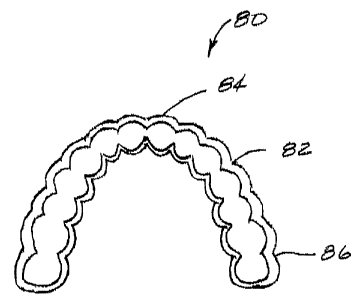
conformed aesthetically pleasing smile. The clinician and the
dental` technician would create a thicker facial aspect as the
dental appliance 80 goes from anterior to posterior. This has
been illustrated in Fig. 6 in which the thickness of the wall 82
has been progressively increased from anterior 84 to posterior
86.
[0046] Another example relates to increasing the vertical
dimension of the teeth. This is an extremely important
application for the dental appliance 10. A common occurrence in
dentistry is a result of severe grinding or bruxism. The only
tissue or structure that creates facial weight is a person's
teeth. Through the years, as a patient grinds or bruxes his or
her teeth, teeth surface is lost and the teeth become shorter and
so does a patient's vertical dimension or facial height. This
can cause a tremendous stress on the tempro-mandibular joint.
In the past, the common treatment was to use the crown and bridge
CA 02623055 2008-03-19
WO 2007/037851 PCT/US2006/032807
8
modality and cap or crown the teeth to restore facial height.
This treatment is done firstly through the use of acrylic
temporaries and this necessitates the doctor to drill down the
teeth to place these crowns even for the use of temporary crown.
Through the years, many patients would be extremely apprehensive
about committing to such a treatment without knowing the final
vertical or facial height. With the dental appliance 90
according to the present invention, the dentist can use the
appliance 90 to increase vertical dimension and achieve over the
same time period that conventional crown and bridge dentistry
takes to create a proper vertical dimension and facial height.
This has been illustrated in Fig. 7. In Fig. 7, the increased
vertical dimensions of the teeth, which are indicated typically
by the numeral 92, has been indicated by the broken line 94.
[0047] The dental appliance 90 can gain more patient
compliance and treatment plan acceptability as well as achieve
the same result without committing the patient to irreversible
crown and bridge therapy. Like any other method of treatment,
careful record taking and treatment planning must be accomplished
before dentist and patient choose the correct choice of
treatment.
[0048] In cases of use of the dental appliance 90, the
increase of vertical dimension, the clinician instructs the
technician to increase thickness on the occlusal aspects and
through proper bite records, the appliance can be made properly.
[0049] The dental appliance 10 is made of acetyl resin which
is much more durable than acrylic, and which is what conventional
crown and bridge temporaries are fabricated of. In some types
of cases, when it is a long term treatment, the dental appliance
would offer the patient more aesthetics and comfort, as well as
the knowledge that this treatment is totally reversible if so
desired.
[0050] The dental appliance 10 has been tested on over 300
patients. The patients seem to accommodate the appliances added
thickness quite well and this seems to be achieved via the design
CA 02623055 2008-03-19
WO 2007/037851 PCT/US2006/032807
9
of the appliance. First, the dental appliance 10 can be made as
thin as 0.4mm in thickness so that the dental appliance, by
itself, can create almost no interference with the occlusal
aspect. Secondly, the design of the dental appliance is such
that the liquid/aspect of the tooth of an upper arch has what we
termed occlusal windows. These allow the supporting cusp to
protrude out of these windows creating intercuspation of the two
arches, so to allow the patient to fully close. The dental
appliance 10 also enables patients to chew food and allows them
to utilize the appliance for extended periods of time.
[0051] The dental appliance 10 allows the patients to wear the
appliance without having the need to use any adhesive or cement
or the preparation of a patient's existing teeth.
[0052] The points of retention of the dental appliance 10 are
best shown in Fig. 5 in which a typical tooth 100 is shown. The
dental appliance 10 is engaged onto the tooth and rides over the
bulge 102 or height 104 of the contour of the tooth 100. The
dental appliance 10 flexes outwardly as this occurs and then
settles right under this height of contour and returns to its
original configuration thereby creating the retentive points 106,
108.
[0053] The retentive points 106, 108 are all supra gingivital
and do not impinge into the gingival tissue 110.
[0054] The utilization of the height 102, 104 of the contour
of the tooth 100 by the dental appliance 10 results in an
extremely large amount of retention capability. This retention
capability ensures that the dental appliance 10 will remain
securely in place during all normal activities.
[0055] In a typical case where the dental appliance 10 covers
twelve teeth, there are 24 areas or surface of retention.
[0056] As indicated previously, a preferred material for the
dental appliance 10 has been found to be acetyl resin. Acetyl
resin in crystallized form has a property which may be defined
as "memory." This property allows the dental appliance to flex
CA 02623055 2008-03-19
WO 2007/037851 PCT/US2006/032807
in order to ride over the contour of the tooth and then flex back
to its original configuration after the dental appliance
encounters the hard tooth structure. When it flexes back to
encounter this hard structure, very strong retentive points are
created, thus preventing the appliance from falling out or
slipping even during mastication.
[0057] The outer surfaces of the dental appliance 10 are made
as thick as the oral cavity will allow. For instance, the space
between the outer surface of a tooth and the inner surface of the
lip defines the space in which the dental appliance can reside.
If the outer surface of the dental appliance is too thick, then
the inner surface of the lip will be irritated. The outer
surfaces of the dental appliance are polished to the highest
possible degree in order to prevent irritation and to prevent
accumulation of tartar. The thickness of the outer surface is
also generally in line with the facial contours of the other
teeth. For instance, if the dental appliance covers eight teeth,
then the teeth on either side of the mid-line act as a guide for
the thickness of the dental appliance.
[0058] In some cases, the dentist will fabricate the dental
appliance 80 in a manner which will widen the smile by building
out the buccal aspect (cheek side) of the dental appliance from
anterior to posterior. An example of this type of case was shown
in Fig. 6. These cases are accomplished when there is arch
restriction of the teeth and there is sufficient space between
the teeth and the cheeks.
[0059] The following steps are followed during the fabrication
and installation of the dental. appliance 10, 80, 90 according to
the present invention.
[0060] Evaluating the patient's dentition and oral cavity, the
focus is on the teeth and their strength. The most important
contraindication to the application of the dental appliance is
severe periodontal disease. Mild periodontal disease is not a
problem as long as the teeth are not severely mobile.
CA 02623055 2008-03-19
WO 2007/037851 PCT/US2006/032807
11
[0061] Creating an accurate impression of the teeth using
stock dental trays. The trays should not touch any of the tooth
structure so that an accurate impression is formed of all of the
tooth surfaces, including facial, buccal and lingual surfaces.
Using a very accurate crown and bridge material preferably a
polyether or a polyvinyl siloxane, an accurate impression is
created of the entire arch for which the dental device is being
fabricated.
[0062] Creating an impression of the counter arch. The
material used for the counter arch impression may be standard
alginate material.
[0063] Creating an accurate bite registration impression using
reposil or other bite registration material.
[0064] Selecting the appropriate color and shade for the
dental appliance in accordance with the desired visual impression
to be created.
[0065] Using the various dental impression and bite
registration impression, fabricating the dental appliance. The
outer contours follow the general contours of the patient's
dentition; however, the visible outer surfaces are fabricated to
provide the desired visual effect by adjusting the thickness of
the dental appliance as needed and adjusting the length and
contour of each tooth to conform with an ideal standard as well
as the aesthetics desired by the patient.
[0066] Installing the dental appliance by snapping the dental
appliance over the patient's dentition into the aforesaid
retentive areas.
[0067] Allowing the patient to sit with the dental appliance
for several minutes in order to accommodate any slight settling,
tongue adaptations and for any pressure areas to subside.
[0068] Checking the occlusion using disclosing paper.
[0069] Performing occlusion adjustments if needed.
[0070] Polishing any areas of the dental appliance which have
been adjusted.
CA 02623055 2008-03-19
WO 2007/037851 PCT/US2006/032807
12
[0071] The foregoing specific embodiments of the present
invention as set forth in the specification herein are for
illustrative purposes only. Various deviations and modifications
may be made within the spirit and scope of the invention without
departing from the main theme thereof.