Note: Descriptions are shown in the official language in which they were submitted.
CA 02623075 2008-02-27
ADJUSTABLE RISER ASSEMBLY
FIELD OF THE INVENTION
[0001] This invention relates generally to snowmobiles and more specifically
to
steering systems for snowmobiles.
BACKGROUND OF THE INVENTION
[0002] Snowmobiles are manufactured in only a limited range of sizes and
configurations, in contrast with the sizes of riders who enjoy riding
snowmobiles. Riders
will often use a snowmobile differently at different times. However, typical
snowmobiles
are designed for riders having a limited range of sizes and for a designated
purpose.
Typical snowmobiles are dedicated to purposes such as racing, long distance
touring,
mountain riding, and the like.
[0003] Such snowmobiles do not accommodate a variety of users and riding
styles. Some attempts have been made to provide adjustable handlebars to
accommodate
riders of different sizes. However, the range of motion of many of these
systems is
limited to adjusting the length of a tube or pivoting a steering tube to which
the
handlebars secure. Such systems do not permit the user to adjust the angle of
the
handlebars in order to compensate for the change in orientation of the
handlebars caused
by the adjustment. Some systems allow greater adjustability but such systems
have
multiple points of adjustment with multiple fastening means, requiring the
user to adjust
one portion of the steering system and secure it, then adjust and secure
another portion,
then asses the suitability of the orientation, and then repeat the process
until a suitable
configuration is found.
[0004] It would therefore be an advancement in the art to provide a system
allowing a user to readily adjust the position and orientation of handlebars
and
conveniently secure the handlebars in a desired orientation and height.
-1-
CA 02623075 2008-02-27
SUMMARY OF THE INVENTION
[00051 A vehicle, such as a snowmobile, includes a handlebar assembly for
steering the vehicle. The handlebar assembly includes a riser pivotally
secured to a
steering shaft and handlebars pivotally secured to the riser. A clamp
selectively engages
both handlebars and steering shaft to fix the position of the riser relative
to the handlebars
and steering shaft.
[0006] The clamp includes upper and lower clamps selectively drawn toward
one another by a locking member. The upper and lower clamps are preferably
pivotally
secured to the riser. In one embodiment, the locking member is a cam-lock
including a
rod having a cam eccentrically and pivotally connected to one end and an
enlargement
secured to the opposite end. A lever secures to the cam. The cam engages one
of the
upper and lower clamps and the enlargement engages the other of the upper and
lower
clamps. Pivoting of the lever causes the cam to shorten or lengthen the
distance between
a lower surface of the cam and the enlargement, thereby locking or releasing
the upper
and lower clamps. To prevent accidental release, a releasable latch secures
the lever to
the rod when the clamps are in a locked position. A spring engaging the riser
and the
lower clamp, biases the lower clamp away from the riser.
BRIEF DESCRIPTION OF THE DRAWINGS
[0007] Preferred and alternative embodiments of the present invention are
described in detail below with reference to the following drawings:
[0008] FIGURE 1 is isometric view of a snowmobile;
[0009] FIGURE 2 is a isometric view of a steering system having an adjustable
riser assembly, in accordance with an embodiment of the present invention;
[0010] FIGURE 3 is an exploded view of a steering system having an adjustable
riser assembly, in accordance with an embodiment of the present invention;
[0011] FIGURE 4 is a isometric view of a cam-lock suitable for use in the
adjustable riser assembly, in accordance with an embodiment of the present
invention;
-2-
CA 02623075 2008-02-27
[0012] FIGURES 5A and 5B are a side views of an adjustable riser assembly in
released and locked positions, in accordance with an embodiment of the present
invention; and
[0013] FIGURE 6 is a isometric view of handlebars suitable for use in the
adjustable riser assembly, in accordance with an embodiment of the present
invention.
DETAILED DESCRIPTION OF THE PREFERRED EMBODIMENT
[0014] Referring to FIGURE 1, a snowmobile 10 typically includes handlebars
12 mounted at the forward end of a seat 14 mounted to a tunnel 16 housing an
endless
track drive system. A driver wishing to travel large distances comfortably
will typically
prefer to have the handlebars positioned such that the user may sit upright
with the legs
bent at a comfortable angle and the arms slightly bent. On the other hand, a
driver
wishing to drive aggressively may sit close to the handle bars in a crouched
position with
the body forward and the arms bent sharply in order to shift the center of
gravity of the
combined snowmobile and driver toward the dimensional center of the snowmobile
to
improve handling. The mountain rider may stand frequently with more upright
hand
forward handlebars.
[0015] In each of these riding styles, the wrist and hands of the user will be
at a
different angle relative to the handlebars. In a similar fashion, the hands
and wrists of
riders having different heights will also be at different angles relative to
the handlebars.
Accordingly, the controls should also be positioned to be comfortably actuated
by users
of different heights and having different riding positions.
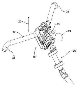
[0016] Referring to FIGURE 2, in one embodiment of the present invention, a
riser assembly 18 secures the handlebars 12 to a steering post 20. The riser
assembly 18
includes a lever 22 operated by a user to release or secure both the
handlebars 12 and the
steering post 20. When released, the handlebars 12 and riser assembly 18 are
permitted to
rotate in rotational direction 24. Accordingly, the handlebars 12 are
pivotable up and
down to accomplish and adjustment in the vertical direction 26. As the riser
18 is pivoted
to adjust the general height of the handlebars 12, the handlebars 12 may be
rotated to
-3-
CA 02623075 2008-02-27
maintain the proper orientation of the handlebars and the various controls
attached thereto
and to accomplish further height adjustment at the ends 28 of the angled
handlebars 12.
[0017] Referring to FIGURE 2 and 3, in one embodiment, the riser assembly 18
includes a frame 30 having seats 32a, 32b formed therein, or secured thereto,
at its upper
and lower ends. The upper seat 32a receives a central portion of the
handlebars 12 and
the lower seat 32b receives a steering post tube 34 secured to the steering
post 20. Upper
and lower clamps 38a, 38b are positionable over the seats 32a, 32b to capture
the
handlebars 12 and steering post tube 34, respectively between the frame 30 and
the
clamps 38a, 38b. In the illustrated embodiment, the clamps 38a, 38b are
pivotally
secured to the frame 30.
[0018] Referring to FIGURE 4, while still referring to FIGURE 3, a lock 40
pulls the clamps 38a, 38b toward the frame 30 to fix the position of the frame
30 relative
to the handlebars 12 and steering post tube 34. In the illustrated embodiment,
the lock 40
is a cam-lock device having a lever 22 actuating an over-center cam 44. The
lever 22 and
cam 44 are pivotally mounted to a rod 46 having an enlarged portion, such as a
cross bar
48 secured to the end opposite the lever 22. In some embodiments, a latch 50
is provided
to maintain the lever in a locked position when the riser assembly 18 is not
being
adjusted. A button 52 secured to a rod 54 is pushed by a user to disengage the
latch 50
from the rod 46 to allow the lever 22 to be actuated to release the clamps
38a, 38b. A
spring may engage the latch 50 and lever 22 to bias the latch 50 in direction
56 toward
engagement with the rod 46. The latch 50 has an angled or rounded surface 58
positioned
such that the latch 50 will be deflected when pressed against the rod 46, such
that the
latch 50 automatically latches to the rod 46 when pressed thereagainst.
[0019] Referring again to FIGURE 3, the cam 44 engages a seat 60 positioned
over an aperture 62 formed in the upper or lower clamp 38a, 38b. The seat 60
typically
includes a wear resistant or low friction material facilitating movement of
the cam 44. In
the illustrated embodiment, the upper clamp 38a includes a recess 64 or inset
portion 64
shaped to receive the cam 44 or seat 60.
-4-
CA 02623075 2008-02-27
[0020] The other of the upper and lower clamps 38a, 38b includes a seat 66
shaped to receive the cross bar 48, or other enlargement, secured to the rod
46. In the
illustrated embodiment, the lower clamp 38b includes two flanges 68 each
having a
concave lower surface sized to receive the cross bar 48. The gap between the
flanges 68
is typically sufficiently large to allow the rod 46 and a mount 70 of the
steering post tube
34 to pass therethrough.
[0021] A biasing mechanism, such as one or more springs 72, bias one or both
of the top and bottom clamps 38a, 38b away from the frame 30. In the
illustrated
embodiment, the springs 72 engage the lower clamp 38b and are positioned near
the free
end of the clamp 38b such that the steering post tube 34 is positioned between
the springs
72 and the hinged end of the clamp 38b.
[0022] In some embodiments, retainers 74 secure to the frame 30 and engage
the steering post tube 34. The retainers 74 restrain the steering post tube 34
against
lateral movement when the lower clamp 38b is released. In some embodiments,
the
retainers 74 may include projections 76 positioned within the ends of the
steering post
tube 34 or surrounding the ends of the steering post tube 34. The projections
76 provide
an axis about which the steering post tube 34 may rotate, such that even when
the clamp
38b is released, the tube 34 is constrained to rotation about the projections
76 rather than
shifting position within the seat 32b and the clamp 38b.
[0023] A preferable method of using the riser assembly 18 is illustrated in
FIGURE 5A and 5B. In the released position of FIGURE 5A, the lever 22 is
pivoted
away from frame 30, rotating the cam 44 such that the smaller radius portion
of the cam
profile is positioned over the seat 60. The springs 72 pivot the lower clamp
38b away
from the frame 30. The springs 72 serve to maintain some clamping force on the
upper
clamp 38a through force transmitted by the rod 46. In this manner, the
handlebars 12 will
retain their original position unless the user applies sufficient force to
overcome the force
of the springs 72. Thus, a user is not required to adjust both the handlebar
angle and riser
-5-
CA 02623075 2008-02-27
angle at the same time, but may readily do so if desired. With the clamps 38a,
38b
released, the frame 30 and handlebars 12 may be rotated.
[0024] Referring to FIGURE 5B, in the locked position, the lever 22 is pivoted
toward the frame 30, rotating the cam 44 such that a larger radius portion of
the cam
profile is positioned over the seat 60. The clamps 38a, 38b are pivoted toward
the frame
30 because of the decreased distance between the cam 44 and the cross bar 48.
In the
locked position, the latch 50 is brought into engagement with the rod 46 to
prevent
accidental lifting of the lever 22.
[0025] In some embodiments, inner surfaces of the clamps 38a, 38b or the seats
32a, 32b include one or more projections or recesses engageable with a
corresponding
projection or recess on the handlebars 12 and steering shaft tube 34 to
restrain the
handlebars 12 and steering shaft tube 34 when the clamps 38a, 38b are drawn
toward the
frame 30. In the illustrated embodiment, the clamps 38a, 38b include splined
or knurled
areas 78 engaging corresponding splined or knurled areas 80 formed on the
handlebars 12
and steering shaft tube 34.
[0026] Referring to FIGURE 6, while referring generally to FIGURE 3, in some
embodiments a stop 82 secures to either the top clamp 38a or the handlebars 12
to limit
the rotation of the handlebars 12. Limiting the range of rotation of the
handlebars 12
promotes safety in the event of accidental release of the lock 40. Limiting
the range of
motion also promotes ease of use by ensuring that the handlebars 12 will
generally be
positioned close to a zone of usable orientations. The stop 82 may also
function to keep
the handlebar 12 generally laterally centered by being captured within the
frame 30, such
as between the sides of the seat 32.
[0027] In the illustrated embodiment, the stop 82 is embodied as a projection
84
welded or otherwise secured to the handlebars 12. In use, the stop 82 is
positioned within
the frame 30. The frame 30 in the illustrated embodiment has a generally boxed
shape
such that the space within the frame 30 provides room for some movement of the
projection.
-6-
CA 02623075 2008-02-27
[0028] While the preferred embodiment of the invention has been illustrated
and
described, as noted above, many changes can be made without departing from the
spirit
and scope of the invention. Accordingly, the scope of the invention is not
limited by the
disclosure of the preferred embodiment. Instead, the invention should be
determined
entirely by reference to the claims that follow.
-7-