Language selection

Search

Patent 2623225 Summary

Third-party information liability

Some of the information on this Web page has been provided by external sources. The Government of Canada is not responsible for the accuracy, reliability or currency of the information supplied by external sources. Users wishing to rely upon this information should consult directly with the source of the information. Content provided by external sources is not subject to official languages, privacy and accessibility requirements.

Claims and Abstract availability

Any discrepancies in the text and image of the Claims and Abstract are due to differing posting times. Text of the Claims and Abstract are posted:

  • At the time the application is open to public inspection;
  • At the time of issue of the patent (grant).
(12) Patent: (11) CA 2623225
(54) English Title: LOCATOR ASSEMBLY
(54) French Title: ENSEMBLE DE POSITIONNEMENT
Status: Deemed expired
Bibliographic Data
(51) International Patent Classification (IPC):
  • B62D 65/00 (2006.01)
  • B62D 25/08 (2006.01)
  • B62D 27/02 (2006.01)
(72) Inventors :
  • KAPADIA, AMEIL A. (United States of America)
  • SCHALTE, GARI M. (United States of America)
  • PILETTE, THOMAS (United States of America)
(73) Owners :
  • MAGNA INTERNATIONAL INC. (Canada)
(71) Applicants :
  • MAGNA INTERNATIONAL INC. (Canada)
(74) Agent: BRANDT, KERSTIN B.
(74) Associate agent:
(45) Issued: 2013-11-12
(86) PCT Filing Date: 2006-09-29
(87) Open to Public Inspection: 2007-04-12
Examination requested: 2011-09-27
Availability of licence: N/A
(25) Language of filing: English

Patent Cooperation Treaty (PCT): Yes
(86) PCT Filing Number: PCT/US2006/038630
(87) International Publication Number: WO2007/041583
(85) National Entry: 2008-03-19

(30) Application Priority Data:
Application No. Country/Territory Date
60/722,273 United States of America 2005-09-30

Abstracts

English Abstract


In accordance with the present invention, there is provided a locator pin (20)
and a retention clip (22) . The locator pin (20) and the retention clip (22)
allow alignment of the front end module (14) with the body structure (12) and
the retention clip (22) secures the two assemblies in place which allows
alignment of fastener holes (16,18) . This conserves time in the assembly line
and allows more accurate and rapid assembly of the front end module on the
body structure reducing the time necessary for assembly.


French Abstract

La présente invention concerne un doigt de positionnement (20) et une agrafe de retenue (22). Le doigt de positionnement (20) et l~agrafe de retenue (22) permettent d~aligner un module frontal (14) avec une structure de châssis (12), et l~agrafe de retenue (22) fixe les deux ensembles en place pour un alignement de trous de fixation (16, 18). Ceci permet un gain de temps dans la chaîne de montage et un montage plus précis et rapide du module frontal sur la structure de châssis, d~où un procédé de production optimisé.

Claims

Note: Claims are shown in the official language in which they were submitted.

Claims
What is claimed is:
1. A locator assembly comprising:
a front end module configured to support one or more body panels of a
vehicle;
a body structure for attachment and support of said front end module
during assembly;
at least one locator hole positioned on said front end module;
at least one locator hole positioned on said body structure;
at least one locator pin extending from said body structure for slidably
engaging said at least one locator hole on said front end module;
at least one locator pin extending from said front end module for slidably
engaging said at least one locator hole on said body structure;
one or more attachment holes on said body structure;
one or more attachment holes on said front end module, wherein said
one or more attachment holes on said body structure align with said one or
more attachment holes on said front end module during assembly;
one or more retaining clips extending from said front end module; and
one or more retention holes on said body structure for receiving said one
or more retaining clips from said front end module.
2. The locator assembly of claim 1 further comprising fasteners placed in said

one or more attachment holes of said body structure and said one or more
attachment holes of said front end module.
3. The locator assembly of claim 1 further comprising:
one or more retaining clips extending from said body structure; and
one or more retaining holes on said front end module for receiving said
one or more retaining clips from said body structure.

4. A locator assembly comprising:
a front end module configured to support one or more body panels, said
front end module having at least one locator pin extending from said front end

module for aligning said front end module during assembly, said front end
module having one or more retaining clips extending from said front end
module;
a body structure for attachment and support of said front end module;
and
one or more retention holes in said body structure for receiving said one
or more retaining clips from said front end module.
5. The locator pin assembly of claim 4 further comprising:
one or more attachment holes on said vehicle body structure;
one or more attachment holes on said front end module, wherein said
one or more said attachment holes on said vehicle body structure align with
said one or more attachment holes on said front end module when said at least
one locator pin is positioned at said at least one locator hole; and
wherein said one or more retaining clips are positioned in said one or
more retaining holes to temporarily support said front end module to said
vehicle body structure during attachment.
6. The locator pin assembly of claim 5 further comprising:
fasteners placed in said one or more attachment holes on said vehicle
body structure and said one or more attachment holes on said front end
module when said at least one locator pin is positioned in said at least one
locator hole.
6

7. A locator assembly comprising:
a front end module configured to support one or more body panels of a
vehicle;
at least one locator hole positioned on said front end module for aligning
said front end module during assembly;
one or more retaining clips extending from said front end module;
a body structure for attachment and support of said front end module;
and
one or more retention holes on said body structure for receiving said one
or more retaining clips from said front end module.
8. The locator pin assembly of claim 7 further comprising:
one or more attachment holes on said vehicle body structure;
one or more attachment holes on said front end module, wherein said
one or more attachment holes on said vehicle body structure align with said
one or more attachment holes on said front end module when said at least one
locator pin is positioned in said at least one locator hole; and
wherein said one or more retaining clips are positioned in said one or
more retaining holes to temporarily support said front end module to said body

structure during attachment.
9. The locator assembly of claim 8 further comprising fasteners placed in said

one or more attachment holes on said vehicle body structure and said one or
more attachment holes on said front end module when said at least one locator
pin is positioned in said at least one locator hole.
10. A locator assembly comprising:
a front end module configured to support one or more body panels, said
front end module having at least one locator hole, said front end module
having
one or more retaining clips extending from said front end module;
a body structure for attachment and support of said front end module
said body structure having at least one locator pin extending from said body
7

structure for slidably engaging at least one said locator hole of said front
end
module during assembly; and
one or more retention holes in said body structure for receiving said one
or more retaining clips from said front end module.
11. A locator assembly comprising:
a front end module configured to support one or more body panels of a
vehicle;
a body structure for attachment and support of said front end module;
at least one locator hole positioned on one of said front end module and
said body structure for aligning said front end module during assembly;
one or more retaining clips extending from said one of said body
structure and front end module; and
one or more retention holes on said other of said body structure and said
front end module for receiving said one or more retaining clips from said one
of
said body structure and front end module.
12. A locator assembly comprising:
a front end module configured to support one or more body panels;
a body structure for attachment and support of said front end module;
at least one locator pin extending from one of said front end module and
said body structure for aligning said front end module during assembly;
at least one locator hole in said other one of said front end module and
said body structure for sliding engagement with said locator pin; and
one or more retention holes in one of said front end module and said
body structure for receiving one or more retaining clips is said other one of
said
front end module and said body structure.
13. A locator assembly as described in claim 12 wherein both of said front end

module and said body structure have at least one extending locator pin and
locator hole.
8

14. A locator assembly as described in claim 12 wherein both of said front end

module and said body structures have at least one retaining clip and one
retention hole receiving one of said retaining clips.
9

Description

Note: Descriptions are shown in the official language in which they were submitted.


CA 02623225 2013-02-13
=
LOCATOR ASSEMBLY
TECHNICAL FIELD
The present invention relates to a locator assembly, in more particularly,
to a locator assembly for temporarily aligning a front module with a body
structure.
BACKGROUND OF THE INVENTION
In the automotive industry, one of the assembly steps is the necessity of
attaching the front end module having various components onto a body
structure. Typically, an assembly person requires a lift-assist to align the
components and thereafter fasteners need to be positioned and fastened for
securing the assembly of the front end module or other modules to the body
structure. Because the rate of production is so high in many cases, this
portion
of the assembly process is more time consuming than the allotted time allowed
for the operation. Therefore, there remains a need in the art to provide a
better
method for allowing alignment of the body structure with a front end or other
module to allow ample time and more efficient fastening of the front end
module to the body structure.
1

CA 02623225 2008-03-19
WO 2007/041583
PCT/US2006/038630
SUMMARY OF THE INVENTION
In accordance with the present invention, there is provided a locating
pin and a retention clip. The locating pin and the retention clip allow
alignment of the front end module with the body structure and the retention
clip secures the two assemblies in place which allows alignment of fastener
holes. This conserves time in the assembly line and allows more accurate
and rapid assembly of the front end module on the body structure reducing
the time necessary for assembly.
Further areas of applicability of the present invention will become
apparent from the detailed description provided hereinafter. It should be
understood that the detailed description and specific examples, while
indicating the preferred embodiment of the invention, are intended for
purposes of illustration only and are not intended to limit the scope of the
invention.
DESCRIPTION OF THE DRAWINGS
The present invention will become more fully understood from the
detailed description and the accompanying drawings, wherein:
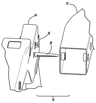
Figure 1 is a perspective view of a front end module and body structure
in which the present invention is used;
Figure 2 is a detailed perspective view of the locator assembly of the
present invention prior to location; and
Figure 3 is a perspective partially assembled view of the locator
assembly of the present invention.
2

CA 02623225 2008-03-19
WO 2007/041583
PCT/US2006/038630
DETAILED DESCRIPTION OF THE PREFERRED EMBODIMENTS
The following description of the preferred embodiment(s) is merely
exemplary in nature and is in no way intended to limit the invention, its
application, or uses.
Referring now to Figs. 1-3, a locator assembly 10 is generally shown.
The locator assembly is used for locating and affixing the body structure 12
to
the front end module 14. As shown in Figure 1, front end module 14 includes
various fixtures attached and is assembled in an assembly line to the body
structure 12. Typically, an operator uses a lift-assist type arrangement to
align a number of mounting holes 16 and 18 between the front end module
and the body structure. Then the module is attached via holes as they are
kept aligned until.
In the present invention, the locator assembly includes a locator pin 20
and a retention clip 22. As shown in Figure 3, locator pin 20 is elongated and
inserted through a location hole 24. This brings the body 12 and module 14 in
alignment. As the parts are assembled toward one another, the retention clip
22 is inserted in the retention hole 26 of the structure member which secures
the front end module 14 with the body structure 12 to allow enough time for
efficient insertion of the fasteners into the holes 16 and 18 for fastening
the
assemblies together.
In the present case, the clip 22 and locator pin 20 are typically made of
a plastic material, however, other materials which will allow retention of the

assembly until fastening is complete such as metal, composite materials, or
the like, can also be advantageously used in the subject invention. The
assembly can be a one piece clip which is inserted through the outside of the
3

CA 02623225 2013-02-13
front end module. Alternatively, these features could be integrally formed
with
a module overmolded into the module or placed into apertures of the front end
module at the respective locations with quick attach assemblies. While the
locator assembly is shown as attached to the front end module, it is also
within
the scope of the present invention to have these features either alone or in
combination attached to the support structure as shown in FIG. 4 noted as
items 51 and 53. Similarly, a clip could be attached to the support structure
with
the pin attached to the module or vice versa.
The description of the invention is merely exemplary in nature and numerous
other embodiments may be envisaged without departing from the scope of the
instant invention.
4

Representative Drawing
A single figure which represents the drawing illustrating the invention.
Administrative Status

For a clearer understanding of the status of the application/patent presented on this page, the site Disclaimer , as well as the definitions for Patent , Administrative Status , Maintenance Fee  and Payment History  should be consulted.

Administrative Status

Title Date
Forecasted Issue Date 2013-11-12
(86) PCT Filing Date 2006-09-29
(87) PCT Publication Date 2007-04-12
(85) National Entry 2008-03-19
Examination Requested 2011-09-27
(45) Issued 2013-11-12
Deemed Expired 2020-09-29

Abandonment History

There is no abandonment history.

Payment History

Fee Type Anniversary Year Due Date Amount Paid Paid Date
Application Fee $400.00 2008-03-19
Maintenance Fee - Application - New Act 2 2008-09-29 $100.00 2008-06-18
Maintenance Fee - Application - New Act 3 2009-09-29 $100.00 2009-06-12
Maintenance Fee - Application - New Act 4 2010-09-29 $100.00 2010-06-15
Maintenance Fee - Application - New Act 5 2011-09-29 $200.00 2011-06-14
Request for Examination $800.00 2011-09-27
Maintenance Fee - Application - New Act 6 2012-10-01 $200.00 2012-06-26
Maintenance Fee - Application - New Act 7 2013-09-30 $200.00 2013-06-27
Final Fee $300.00 2013-08-26
Maintenance Fee - Patent - New Act 8 2014-09-29 $200.00 2014-09-04
Maintenance Fee - Patent - New Act 9 2015-09-29 $200.00 2015-09-09
Maintenance Fee - Patent - New Act 10 2016-09-29 $250.00 2016-09-08
Maintenance Fee - Patent - New Act 11 2017-09-29 $250.00 2017-09-06
Maintenance Fee - Patent - New Act 12 2018-10-01 $250.00 2018-09-05
Owners on Record

Note: Records showing the ownership history in alphabetical order.

Current Owners on Record
MAGNA INTERNATIONAL INC.
Past Owners on Record
KAPADIA, AMEIL A.
PILETTE, THOMAS
SCHALTE, GARI M.
Past Owners that do not appear in the "Owners on Record" listing will appear in other documentation within the application.
Documents

To view selected files, please enter reCAPTCHA code :


To view images, click a link in the Document Description column. To download the documents, select one or more checkboxes in the first column and then click the "Download Selected in PDF format (Zip Archive)" or the "Download Selected as Single PDF" button.

List of published and non-published patent-specific documents on the CPD .

If you have any difficulty accessing content, you can call the Client Service Centre at 1-866-997-1936 or send them an e-mail at CIPO Client Service Centre.


Document
Description 
Date
(yyyy-mm-dd) 
Number of pages   Size of Image (KB) 
Abstract 2008-03-19 2 69
Claims 2008-03-19 4 147
Drawings 2008-03-19 3 42
Description 2008-03-19 4 125
Representative Drawing 2008-06-19 1 6
Cover Page 2008-06-19 2 38
Claims 2013-02-13 5 162
Description 2013-02-13 4 118
Cover Page 2013-10-09 1 36
PCT 2008-03-19 5 192
Assignment 2008-03-19 4 116
Prosecution-Amendment 2011-09-27 1 28
Prosecution-Amendment 2012-07-24 1 25
Prosecution-Amendment 2012-08-14 2 87
Prosecution-Amendment 2013-02-13 10 287
Correspondence 2013-08-26 1 24