Note: Descriptions are shown in the official language in which they were submitted.
CA 02623262 2012-12-10
54106-358
- I -
CONTROL METHOD FOR DIRECT CURRENT TRANSMISSION BY MEANS OF
SEVERAL POWER CONVERTERS
Description
The present invention relates to a method for
controlling at least three converters, which can be controlled
as rectifiers or inverters and are connected to one another via
a DC power supply system, in the field of power distribution
and transmission.
Some methods are already known, for example, from
DE 195 44 777 Cl. The method described there is used to
control a so-called high-voltage direct-current transmission
system, which comprises a plurality of converters, in which
case the converter may be selectively operated as inverters or
rectifiers. In this case, the converters are connected to one
another via a DC power supply system. Transformers are
provided in order to couple the converters to a respectively
associated power distribution system. The direct currents and
DC voltages are recorded as measured values at the respective
converters in order to control the rectifiers or inverters.
Furthermore, nominal value pairs in the form of a nominal
current and nominal voltage are defined for each converter.
Each control system calculates a control discrepancy relating
to this, that is to say in other words it forms the difference
between the measured values and nominal values. The rectifiers
are controlled such that the sum of the control discrepancies
is minimized. In contrast, the inverters are controlled such
that the difference between the control discrepancies is
minimized. The already known method has the disadvantage that
it requires a higher control level. However, a hierarchical
CA 02623262 2012-12-10
54106-358
- 2 -
control structure is complex and can lead to undesirable
instabilities.
Some embodiments of the present invention may provide
a method for controlling converters, which has a simple
structure and at the same time operates reliably and in a
stable manner.
Some embodiments of the invention may provide a
method in which a respective measured DC voltage and a
respective measured direct current are measured at each
converter and are transmitted to a rectifier control system in
order to control the respective rectifier, or to an inverter
control system in order to control a respectively associated
inverter, a respectively associated rectifier nominal DC power
and a respective inverter nominal DC power are defined for each
rectifier control system and for each inverter control system,
with the sum of all the rectifier nominal DC powers and all the
inverter nominal DC powers being equal to zero, a respectively
associated inverter nominal DC voltage is determined from each
inverter nominal DC power, the lowest inverter nominal DC
voltage of all the inverters which are connected to the DC
power supply system is defined as the minimum DC voltage, a
rectifier nominal direct current and an inverter nominal direct
current are respectively calculated by means of the minimum DC
voltage from each rectifier nominal DC power and from each
inverter nominal DC power, with each rectifier control system
forming the difference between the minimum DC voltage and the
respectively received rectifier measured DC voltage, resulting
in a rectifier difference DC voltage, and forming the
difference between the respective rectifier nominal current and
the respectively received rectifier measured direct current,
CA 02623262 2012-12-10
' 54106-358
- 3 -
resulting in a rectifier difference direct current, and
controlling the associated rectifier such that the sum of the
difference DC voltage and the difference direct current is
minimized, and with each inverter control system forming the
difference between the minimum DC voltage and the respectively
received inverter measured DC voltage, resulting in an inverter
difference DC voltage, and forming the difference between the
respective inverter nominal current and the respectively
received inverter measured direct current, resulting in an
inverter difference direct current, and controlling the
respectively associated inverter such that the difference
between the inverter difference direct current and the inverter
difference DC voltage is minimized.
According to an aspect of the present invention,
there is provided a method for controlling at least three
converters which can be controlled as rectifiers or inverters
and are connected to one another via a DC power supply system,
in the field of power distribution and transmission, in which a
respective measured DC voltage and a respective measured direct
current are measured at each converter and are transmitted to a
rectifier control system in order to control the respective
rectifier, or to an inverter control system in order to control
a respectively associated inverter, a respectively associated
rectifier nominal DC power and a respective inverter nominal DC
power are defined for each rectifier control system and for
each inverter control system, with the sum of all the rectifier
nominal DC powers and all the inverter nominal DC powers being
equal to zero, a respectively associated inverter nominal DC
voltage is determined from each inverter nominal DC power, the
lowest inverter nominal DC voltage of all the inverters which
are connected to the DC power supply system is defined as the
CA 02623262 2012-12-10
54106-358
- 3a -
'
minimum DC voltage, a rectifier nominal direct current and an
inverter nominal direct current are respectively calculated by
means of the minimum DC voltage from each rectifier nominal DC
power and from each inverter nominal DC power, with each
rectifier control system forming the difference between the
minimum DC voltage and the respectively received rectifier
measured DC voltage, resulting in a rectifier difference DC
voltage, and forming the difference between the respective
rectifier nominal current and the respectively received
rectifier measured direct current, resulting in a rectifier
difference direct current, and controlling the associated
rectifier such that the sum of the difference DC voltage and
the difference direct current is minimized, and with each
inverter control system forming the difference between the
minimum DC voltage and the respectively received inverter
measured DC voltage, resulting in an inverter difference DC
voltage, and forming the difference between the respective
inverter nominal current and the respectively received inverter
measured direct current, resulting in an inverter difference
direct current, and controlling the respectively associated
inverter such that the difference between the inverter
difference direct current and the inverter difference DC
voltage is minimized.
Fundamentally, some embodiments of the invention may
avoid the need not only for a hierarchical structure of the
control method but also for control separation.
By way of example, the power nominal values for the
control systems for the converters are defined by a central
control point, with the power nominal values being transmitted
from the control point via an expedient form of data
CA 02623262 2012-12-10
54106-358
- 3b -
transmission to the individual control systems. However, the
invention avoids the need for a higher-level control system, as
has become known from the prior art, actively intervening in
the control process in specific, previously defined situations.
The control point just defines the necessary power nominal
values. In fact, instead of the central higher-level control
system, the lowest inverter nominal DC voltage is selected and
the selected minimum DC voltage is used as the nominal DC
voltage for all the control systems for the converters. This
avoids excessively high DC voltages on the DC voltage side of
the converters, so that the invention avoids the need for a
higher-level control system. The method according to the
invention is therefore decentralized, more dynamic, less
complex and more stable than the methods known from the prior
art. The lowest
CA 02623262 2008-03-20
PCT/DE2005/001708 - 4 -
2005P17201W0US
inverter nominal DC voltage is preferably selected on a
decentralized basis, that is to say separately for each control
system.
It should be noted that, for example, the measured values are
recorded by means of current transformers and/or voltage
transformers, whose output signal is in each case proportional
to a monitored DC voltage, for example 500 kV, and/or to a
direct current, for example 3000 A, that is produced by this DC
voltage. The output signal from the current transformer or from
the voltage transformer is, finally, sampled by a sampling unit
in order to produce sample values, and the sample values are
converted to digital measured values by an analogue/digital
converter. In other words, the measured DC voltage and the
measured direct current are, for example, digital measured
values which are supplied to the respective control system and
are processed further by its software.
Each rectifier and each inverter is advantageously controlled
over the entire operating range of the rectifier and,
respectively, of the inverter both on the basis of the
respectively associated rectifier difference direct current and
on the basis of the rectifier difference DC voltage and,
respectively, on the basis of the respectively associated
inverter difference direct current and on the basis of the
associated inverter difference DC voltage. This expedient
further development means that control limiting at the sum of
or the difference between the difference direct current and the
difference DC voltage can be dispensed with. This avoids
control separation and even further enhances the stability of
the method.
CA 02623262 2008-03-20
PCT/DE2005/001708 - 5 -
2005P17201WOUS
The converters are advantageously positioned physically
alongside one another in order to form a back-to-back link. The
back-to-back link formed in this way is used, for example, in
order to couple a plurality of AC voltage power supply systems.
In one further development of the invention, which differs from
this, the converters are positioned at least one kilometer away
from one another in order to form a long-distance direct-
current transmission system. This further development of the
method according to the invention allows electrical power to be
transmitted over long distances between more than two
converters, as a traditional field of application of a direct-
current transmission system. In this case, the converters are
generally positioned such that they are separated from one
another at several hundred kilometers, and are connected to one
another via a direct-current link of appropriate length, and
are networked and coupled to form a DC power supply system.
This allows power transmission between a plurality of grid
points over relatively long distances with low losses.
In one exemplary embodiment, a control point transmits the
nominal DC power, as defined by the user of the method
according to the invention, with details of the operating mode
as a rectifier or inverter to the respectively associated
control system for the converters, with each control system
having means to determine the inverter nominal DC voltage from
the transmitted nominal DC power. Means such as these are, for
example, function transmitters with a characteristic whose
profile is dependent on the design and configuration of the
respective converter, and of the entire installation, and on
empirical values. The inverter control systems send the nominal
DC voltage determined by them to the other control systems by
means of long-distance data transmission.
CA 02623262 2008-03-20
PCT/DE2005/001708 - 6 -
2005P17201W0US
In the long-distance direct-current transmission process which
can be carried out by means of the further development
according to the invention, the respectively required nominal
values, such as the respective nominal DC voltage, are
interchanged between the converters by long-distance data
transmission means. Expedient long-distance data transmission
means include both cable-based transmission means, such as the
Internet or communication via high-voltage lines, and
transmission means without cables, such as radios or the like.
The rectifier and the inverter expediently each have a bridge
circuit formed by thyristors. In comparison to other power
semiconductor valves, thyristors operate with low losses and
are used in particular for high-voltage direct-current
transmission.
Each rectifier measured direct current, which is normalized
with respect to a rated current, is expediently renormalized
with respect to the respectively associated rectifier nominal
direct current, which is likewise normalized with respect to
the rated current, each inverter measured direct current which
has been normalized with respect to the rated current is
renormalized with respect to the respectively associated
inverter nominal direct current, which has likewise been
normalized with respect to the rated current, and both each
rectifier measured DC voltage and each inverter measured DC
voltage which have been normalized with respect to the rated
voltage are renormalized with respect to the minimum voltage,
with each rectifier difference direct current and each inverter
difference direct current being calculated as the difference
between unity and the respectively associated rectifier
measured direct current, which has been renormalized in this
way, and the respective inverter measured direct current, which
has been renormalized in this way, and with the rectifier
difference DC voltage and the inverter difference DC voltage
being calculated as the difference between unity and the
CA 02623262 2008-03-20
PCT/DE2005/001708 - 6a -
2005P17201W0US
respectively associated rectifier measured DC voltage, which
has been renormalized in this way, and the respective inverter
measured DC voltage which has been renormalized in this
CA 02623262 2008-03-20
PCT/DE2005/001708 - 7 -
2005P17201W0US
way. According to this advantageous further development, the
values are renormalized while maintaining the required
transmission power, that is to say the nominal DC power. This
renormalization process is particularly advantageous when
operating on low loads. The marginal-current process according
to the prior art has a poor control response in the low-load
range even in powerful AC voltage power supply systems, that is
to say in AC voltage power supply systems with a high so-called
short-circuit ratio, that is to say the ratio of the power
system short-circuit power to the rated power of the direct-
current transmission system. By way of example, a high short-
circuit ratio is 5. The further development according to the
invention in contrast allows the desired operating points to be
approached quickly even in the low-load range.
Advantageously, a measured turn-off angle is measured at each
inverter and is transmitted to a respectively associated gamma
control system, with the gamma control system comparing the
measured turn-off angle with a nominal turn-off angle
associated with that inverter, and, if the respective measured
turn-off angle is less than the associated nominal turn-off
angle, producing an inverter DC voltage nominal value which is
less than the predetermined inverter nominal DC voltage, with
the reduced inverter DC voltage nominal value being transmitted
to all the other inverter control systems and all the other
rectifier control systems, and being used to determine the
minimum DC voltage. According to this further development of
the invention, a gamma control system is provided in order to
reliably avoid commutation errors when turning on the converter
valves in each inverter. However, in contrast to the prior art,
this avoids competitive control using minimum or maximum
selection between a gamma control system and, for example, a
current control system, for the purposes of the invention.
According to the invention,
CA 02623262 2008-03-20
PCT/DE2005/001708 - 8 -
2005P17201W0US
the gamma control system does not operate when the installation
to be controlled is being operated normally. For this purpose,
for example, a gamma regulator for the gamma control system is
locked to the inverter nominal DC voltage set by a user of the
method. For this purpose, the gamma regulator is limited, for
example at the top, to this selected inverter nominal DC
voltage. If the selected nominal turn-off angle is undershot,
the gamma control system, in contrast, defines an inverter
nominal DC voltage which is less than the originally selected
inverter nominal DC voltage as the inverter DC voltage nominal
value, which is then used to determine the minimum DC voltage.
For this purpose, the inverter DC voltage nominal value is
advantageously sent to all the control systems. The gamma
regulator also expediently has a lower control limit, which
ensures that the reduced inverter nominal DC voltage does not
fall below a lower threshold value.
According to a further advantageous further development of the
invention, each rectifier control system has a limiting
regulator which limits a rectifier regulator in this rectifier
control system at the top such that a predetermined maximum
current and/or a predetermined maximum voltage are/is not
exceeded. The limit, which comes into force for example in the
event of a fault, is used to protect the controlled systems and
for additional stabilization of the method according to the
invention.
According to one expedient further development relating to
this, the limiting regulator limits the associated rectifier
regulator when the respectively received rectifier measured
direct current is greater than the sum of the respective
rectifier nominal direct current and a predetermined difference
direct-current discrepancy, which is in each case associated
with the rectifier, or when
CA 02623262 2008-03-20
PCT/DE2005/001708 - 9 -
2005P17201W0US
the respectively received rectifier measured DC voltage is
greater than the sum of the minimum DC voltage and a
predetermined difference DC voltage discrepancy. The difference
DC current discrepancy and the difference voltage discrepancy
make it possible to set up any desired tolerance band in which
a discrepancy between the respective measured value and the
associated nominal value is permissible without infringing the
rectifier control system limit as described above.
According to one expedient further development, if the
rectifier measured DC voltage and/or the inverter measured DC
voltage are/is falling, the rectifier nominal DC power and/or
the respective inverter nominal DC power are/is reduced as a
function of the respective rectifier measured DC voltage and/or
as a function of the respective inverter measured DC voltage to
a lower value, resulting in a respectively associated fault
nominal DC power, with the rectifier nominal direct current
and/or respectively the inverter nominal direct current being
determined from the respective fault nominal DC power rather
than from the rectifier nominal DC power and/or the respective
inverter nominal DC power. The decrease in the nominal DC power
is used to control the direct-current transmission system in
the event of a fault in which, for example, a voltage dip
occurs in one of the AC voltage power supply systems or in the
DC circuit.
According to one expedient further development relating to
this, the fault nominal DC power is defined using a function
transmitter which is provided with a characteristic based on
empirical values. In this case, the measured DC voltage is
expediently smoothed, and is supplied to the function
transmitter. The measured DC voltage generally has to be
smoothed since the measured DC voltage may
CA 02623262 2008-03-20
PCT/DE2005/001708 - 10 -
2005P17201WOUS
fluctuate severely in the event of a fault. The function
transmitter produces a fault limiting power as a function of
the smoothed measured DC voltage. This is expediently used to
limit the output value of an integrator at the top, with the
output value of the integrator being the fault nominal DC
power. The output of the integrator is used to determine the
nominal DC voltage and the nominal direct current. During
normal operation, the output value of the integrator is equal
to the nominal DC power selected by the user, in other words
the fault handling process is inactive during normal operation.
If, in contrast, the respective measured DC voltage falls below
a predetermined threshold value, the function transmitter
produces a fault limiting power which is lower than the nominal
DC power. Initially, this is then the output value of the
integrator, and therefore at the same time the fault nominal DC
power. If the smoothed measured DC voltage at the input of the
function transmitter rises, it produces an increased fault
limiting power as the upper limit for the integrator. The
integrator then integrates to the increased fault limiting
power, for example at a variable integration rate. In one
preferred exemplary embodiment the integration rate is made
dependent on the nature and magnitude of the fluctuation in the
measured DC voltage. In this case, the fluctuation of the
measured DC voltage is used as an indication as to whether a
given fault is still present or has already been overcome.
The method according to the invention is suitable not only for
high-voltage direct-current transmission, and medium-voltage
direct-current transmission but also for low-voltage direct-
current transmission.
CA 02623262 2008-03-20
PCT/DE2005/001708 - 11 -
2005P17201W0US
Further expedient refinements and advantages of the invention
are the subject matter of the following description of
exemplary embodiments of the invention, with reference to the
figures in the drawing, in which the same reference symbols
refer to components having the same effect, and in which:
Figure 1 shows one exemplary embodiment of the method
according to the invention, on the basis of a
high-voltage direct-current long-
distance
transmission system having a plurality of
converters; and
Figure 2 shows a detail view of the installation shown in
Figure 1, in order to illustrate fault limiting
in one exemplary embodiment of the method
according to the invention.
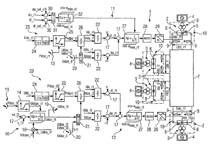
Figure 1 illustrates one exemplary embodiment of the method
according to the invention, in the form of a schematic
illustration. The figure shows a so-called multiterminal high-
voltage direct-current transmission (MT-HVDC) system 1 with a
plurality of converters 2, which are controlled by the
illustrated exemplary embodiment of the method according to the
invention. The MT-HVDC system 1 has a power supply system
connecting transformer 3 for each converter 2, which
transformers 3 are intended to couple the respective converter
2 to an AC voltage power supply system 4. In this case, each
power supply system connecting transformer 3 has a primary
winding, which is galvanically connected to the AC voltage
power supply system 4 and is inductively connected to two
secondary windings on the power supply system connecting
transformer 3. The secondary windings on the power supply
system connecting transformers provide a different phase shift,
therefore providing a so-called 12-pulse HVDC system 1 with a
plurality of converters 2. 12-pulse MT-HVDC systems are very
well known
CA 02623262 2008-03-20
PCT/DE2005/001708 - 12 -
2005P17201W0US
by those skilled in the art in this field, so that they do not
need to be described in any more detail at this point.
The secondary windings of the power supply system connecting
transformers 3 are each connected to a bridge circuit composed
of thyristors 5, which are illustrated only schematically in
Figure 1. Bridge circuits such as these are likewise very well
known. A more detailed description is therefore likewise
superfluous in this case. The bridge circuit formed from
thyristors 5 is controlled in the exemplary embodiment
illustrated in Figure 1 so as to provide a plurality of
rectifiers 6. The rectifiers 6 are connected via a DC power
supply system 7 to a plurality of inverters 8, with the DC
circuit 7 being grounded via resistors 9 to the converters 2.
Smoothing inductors 10 are provided in order to smooth the
direct current and are connected in the link between each
converter 2 and the DC power supply system 7. Each converter 2
may, of course, be operated both as an inverter and as a
rectifier.
Each rectifier 6 and each inverter 8 has current transformers
which are designed to detect a direct current flowing in the
rectifier 6 associated with it or a direct current flowing to
the inverter 8 associated with it. At their outputs, the
current transformers produce a signal which is proportional to
the direct current flowing to the rectifier 6 or to the
inverter 8. The direct current can be determined from the
measurement signal by the use of calibrated appliances. The
measurement signal is sampled by means of a sampling unit,
resulting in sample values, and the sample values are digitized
by an analog/digital converter in order to produce measured
direct-current values, with the measured direct-current values
of the rectifiers being referred to as the rectifier measured
direct current Idc rr and the measured direct current values of
_
the inverters being referred to as the inverter measured direct
current Idc ii.
_
CA 02623262 2008-03-20
PCT/DE2005/001708 - 13 -
2005217201W0US
A measurement signal which is proportional to the DC voltage
which is dropped across each rectifier 6 is detected across the
resistors 9. This signal is also sampled and digitized,
resulting in digital measured DC voltage values, which in this
case are referred to respectively as the rectifier measured DC
voltage Udc_rr and the inverter measured DC voltage Udc_ii.
In the MT-HVDC system 1, the rectifier 6 and the inverter 8 are
several kilometers apart from one another.
Converter control systems are provided in order to control the
converters 2, with each rectifier having a rectifier control
system 11, and each inverter 8 having an inverter control
system 12. For clarity reasons, Figure 1 shows only one
rectifier control system 11 and one inverter control system 12.
A respective rectifier nominal DC power Pdco_r1...Pdco_rr and
an inverter nominal DC power Pdco_il...dco_ii are defined by a
control point, which is not illustrated in the figures, for
each rectifier 6 and for each inverter 8, respectively. The
nominal DC powers are sent from the control point to a radio
receiver 13 for each converter 2.
The inverter control system 12 will be described first of all
in the following text. In each inverter control system 12, the
inverter nominal DC power Pdco_il received by the radio
receiver 13 is supplied to a function transmitter 14. The
function transmitter 14 has a characteristic which is used to
determine an inverter nominal DC voltage Udcpo_i1 as a function
of the received inverter nominal DC power
CA 02623262 2008-03-20
PCT/DE2005/001708 - 14 -
2005P17201W0US
Pdco il. The profile of the characteristic of the function
transmitter is dependent on the structure, the configuration
and the design of the HVDC installation, and is also based on
empirical values.
The inverter nominal DC voltage Udcpo_il calculated by the
function transmitter 14 is used as an upper limit for a gamma-
PI regulator 15 of a gamma control system 16 which has means
(which are not illustrated in the figures) for determining a
measured turn-off angle 'tji for the associated inverter 8.
Furthermore, the gamma control system 16 has a nominal turn-off
angle 70_11, which is applied to the negative input of the adder
17 and, in other words, is subtracted from the measured turn-
off angle 1111. The gamma control system 16 has said gamma-PI
regulator 15 and a multiplier 18 in addition to the adder 17.
The multiplier 18 is used to define the lower limit for the
gamma regulator 15 from the inverter nominal DC voltage
Udcpo_il, with Udcpo_il being multiplied by a factor LL_Udco_il
which is likewise predetermined. In the illustrated exemplary
embodiment the factor LL Udco il is equal to 0.7. The gamma
regulator 15 is accordingly limited at the top to the inverter
nominal DC voltage Udcpo_il and at the bottom to 70% of the
inverter nominal DC voltage Udcpo_il. During normal operation,
the gamma control system 16 is inactive, so that the upper
limit value Udcpo_il is the output value for the integrator 15
Udco il at the same time. However, if commutation errors can be
expected as a result of a corresponding measured turn-off angle
y11, the gamma-PI regulator 15 sets an expedient inverter
nominal DC voltage Udco_il, which is sent via a radio
transmitter 19 to all the rectifier control systems 11 and to
all the other inverter control systems 12. Each rectifier
control system 11 as well as each inverter control system 12
has a radio receiver 20 for receiving the transmitted inverter
nominal DC voltages Udco_i2, Udco ii
from all the
inverters 8, or from all the other inverters 8. The
CA 02623262 2008-03-20
PCT/DE2005/001708 - 15 -
2005P17201W0US
inverter nominal DC voltages Udc_il...Udc_ii are compared with
one another by a minimum selection unit 21, with the minimum
selection unit 21 determining the lowest inverter nominal DC
voltage value as the minimum DC voltage Udco. The rest of the
control process for the inverter 8 and for the rectifier 6 is
now carried out on the basis of the minimum voltage Udco, which
is common to all the control systems.
The minimum DC voltage Udco is used for renormalization of the
inverter measured DC voltage Udc_il. For this purpose, the
inverter measured DC voltage Udc_il and the minimum DC voltage
Udco are supplied to a divider 22 which divides the inverter
measured DC voltage Udc_il by the minimum DC voltage. The
output of the divider 22 is connected to a negative input of an
adder 17, with -1 being applied to its second input. An
inverter difference DC voltage du_il is calculated in this way.
The inverter difference direct current di il is added to the
inverter difference direct current di ii by means of the adder
17.
The process of determining the inverter difference direct
current di ii will be explained in the following text. Each
inverter control system 12 and each rectifier control system 11
has a limiting device 23 which comprises a smoothing unit 24
and a function transmitter 25. The limiting unit 23 decreases
the originally required inverter nominal DC power or rectifier
nominal DC power Pdco_il or the Pdco_rl, respectively, as a
function of the respectively measured inverter measured DC
power Udc_il or Udc_r1 to Pvdpo_il or Pvdpo_rl, respectively.
This is expediently done after the collapse of the DC voltage
in the event of a fault, that is to say for example in the
event of a fault in one of the AC voltage power supply systems
4 or
CA 02623262 2008-03-20
PCT/DE2005/001708 - 16 -
2005P17201W0US
else within the DC power supply system 7. Once the fault has
been rectified, the DC voltage on the DC voltage link 7 is
first of all increased before the nominal DC power is raised to
the original respective value Pdco_il or Pdco_rl. The details
of the method of operation of the limiting device 23 will be
described in conjunction with Figure 2. During
normal
operation, the output of the function transmitter 25 Pvdpo_il
or Pvdpo_rl, respectively, is equal to the respectively
predetermined inverter nominal DC power Pdco_il or the
rectifier nominal DC power Pdco_rl.
The output from the function transmitter 25 is supplied to a
divider 26 which divides the respective nominal DC power by the
minimum DC voltage Udco resulting in an inverter nominal direct
current Idco il or a rectifier nominal direct current Idco rl.
The inverter measured direct current Idc il or the rectifier
measured direct current Idc rl is then renormalized by means of
the divider 22, and the inverter difference direct current
di ii or, respectively, the rectifier difference direct current
dinl is then determined by the adder 17. The inverter
difference DC voltage du_il is subtracted from the inverter
difference direct current di il at the inverter 8. This is done
using the equation di ii - du il = 1 - x Idc - 1 + x
Udc rl,
_ _ _ _
where x Idc il and x Udc il are intended to represent the
_ _ _ _
renormalized measured variables. The difference formed in this
way is intended to be minimized or, in other words, regulated
at zero. For this purpose, the output of the adder 17 is
supplied to an inverter PI regulator 27 which determines the
cosine of the trigger angle a at its output. In this case, the
inverter PI regulator 27 is limited at the top and bottom to a
maximum trigger angle am ax and a minimum trigger angle amin. The
inverter PI regulator 27 is
CA 02623262 2008-03-20
PCT/DE2005/001708 - 17 -
2005P17201W0US
followed by an arccosine unit 28, which determines the
arccosine and thus the trigger angle a, and supplies them to a
trigger generator 29, which produces a trigger pulse for the
thyristors 5 in the inverter 8, as a function of the
transmitted trigger angle a.
Each rectifier control system 11 is essentially designed in a
corresponding manner to the described inverter control system
12, although the rectifier control system 11 has no gamma
regulator 16, and, of course, the rectifier control system 11
does not produce an inverter nominal DC voltage, but has said
minimum selection unit 21 in order to define the minimum DC
voltage Udco.
Like the inverter control system 12, the rectifier control
system 11 also has a limiting device 23 and carries out
renormalization by means of the divider 22. However, the adder
17 which precedes the PI DC voltage regulator 27 does not form
the difference between the rectifier difference current and the
rectifier difference voltage but, instead of these, the sum of
the rectifier difference current and the rectifier difference
voltage, to be precise, after renormalization, using the
formula: di rl + dunl = 1 - x Idc rl + 1 - x Idc rl.
_ _ _ _
In contrast to the inverter control system 12, the rectifier PI
regulator 27 has a maximum current limit and/or maximum voltage
limit. Two adders 30 as well as a minimum selection unit 31 and
a PI regulator 32 are provided for this purpose. The PI
regulator 32 acts on the upper limit of the rectifier PI
regulator 27. The adders 30 add a maximum difference voltage
discrepancy du xxl and a maximum difference current discrepancy
di xxl respectively to the difference DC voltage dunl and to
the difference direct current di rl, in each
CA 02623262 2008-03-20
PCT/DE2005/001708 - 18 -
2005P17201W0US
case. If the rectifier measured direct current Idc rl exceeds a
resultant rectifier nominal current value, which is calculated
from the sum of the rectifier nominal direct current Idco rl
and the maximum difference current discrepancy di_xxl, the
rectifier measured direct current is reduced with the aid of
the PI regulator 32 to the resultant rectifier nominal current
value. In a corresponding manner. The rectifier measured DC
voltage Udc_r1 is reduced to a resultant rectifier nominal
voltage value, which is obtained from the sum of the rectifier
nominal DC voltage Udco_r1 and the maximum difference voltage
discrepancy du_xxl. The greatest discrepancy results from the
minimum selection unit 31. For this purpose, the output of the
minimum selection unit 31 is supplied to the PI regulator 32
which, at its output, produces a cosine of a control angle
between cos ared_r1 and cos araln_rl. The output of the PI
regulator 32 is used to limit the PI regulator 27 in the
rectifier control system 11 at the top. Typical values for
du xxl and di xxl are between 0.01 and 0.1. Depending on the
performance of the HVDC installation, the limit ared_r varies
between 40 and 50 . The minimum turn-off angle of the
rectifier araiii_r1 is normally 50
.
At this point, it should be mentioned once again that the
values to be added are, of course, normalized values. In other
words, the measured values are normalized with respect to so-
called rated values before renormalization.
Figure 2 illustrates the effect of the limiting device 23 in
more detail using the example of a rectifier 6. The rectifier
measured DC voltage Udc_r1 is thus supplied to the smoothing
unit 24 in order to smooth the voltage fluctuations, which
frequently occur in the event of a voltage dip in one of the AC
voltage power supply systems 4, or in the event of some other
fault, and therefore to covert them to rectifier measured DC
voltages Udc_r1 which can be
CA 02623262 2008-03-20
PCT/DE2005/001708 - 19 -
2005P17201WOUS
processed. The smoothed rectifier measured DC voltage is
supplied to the function transmitter 25 together with the
rectifier nominal DC power Pdco_r1 which has been normalized
with respect to the respective rated value. At its output, the
function transmitter 25 produces a normalized fault limiting
power Pvdpol_r1 on the basis of a characteristic that is based
on the experience of the designer of the MT-HVDC system. If the
smoothed rectifier measured DC voltage Udc_r1 exceeds a maximum
DC voltage Umax_r1 as a threshold value, the function
transmitter 25 produces the rectifier nominal DC power Pdco_rl,
as applied to its input, at its output.
The output of the function transmitter 25 is used for maximum
limiting of an integrator 33, with the minimum output voltage
of the integrator 33 Pmino. Furthermore, a limit-value
signaling device 34 with two inputs is provided. The rectifier
measured DC voltage Udc_r1 is applied to the first input of the
limit-value signaling device 34. The maximum voltage Umax_r1 of
the function transmitter 25 is fed to the second input. The
limit-value signaling device 34 compares the two input values.
If the rectifier measured DC voltage Udc_r1 is greater than the
maximum voltage Umax_rl, as is normally the case during rated
operation, the output Y of the limit-value signaling device 34
is set to be equal to unity. If the rectifier measured DC
voltage Udo_ri falls below the maximum voltage Umax_r1 the
output of the limit-value signaling device 34 will in contrast
be equal to zero. A fault situation therefore results in a zero
as a factor in a multiplier 35, so that the integrator 33
produces values Pvdpo rl between the minimum power Pmino and
the maximum power Pdco_r1 as a function of the drop in the
rectifier measured DC voltage Udc_rl. As can be seen from
Figure 1, the rectifier difference direct current dinl is in
_
this case determined on the basis of Pvdpo rl.
CA 02623262 2008-03-20
PCT/DE2005/001708 - 20 -
2005P17201W0US
After fault rectification, the rectifier measured DC voltage
Udc rl rises. The characteristic of the function transmitter 25
_
results in this leading to an increase of Pvdpol_r1 at its
output. The output of the integrator 33 is, however, first of
all locked at the lowest value Pvdpol_r1 which occurred while
the fault existed. However, if the comparator 34 signals that
the rectifier measured DC voltage Udc_r1 is above a threshold
value Umax _rl, the integrator 33 integrates to the value
Pvdpol_r1 produced by the function transmitter 25. Finally,
Pdpo_rl, Pvdpol_r1 and Pdco_r1 match one another, so that a
change is made to normal operation.
The remaining components illustrated in Figure 2 are used for
the capability to adjust the integration rate of the integrator
33 from Pmino until the rectifier nominal DC power Pdco_r1 is
reached. A limiter 36 is first of all provided in order to
define the integration rate, and checks whether the rectifier
measured DC voltage Udc_r1 is in the range between Umin and
WUmin. If Udc rl is below Umin, then Umin is produced at the
_
output of the comparator 36, so that a zero signal is produced
at the output of the downstream adder 37, to whose negative
input Umin is applied. The divider 38 therefore likewise
produces a zero signal at its output, from which previous
voltage values are subtracted by means of the adder 39. The
previous voltage values between 0 and 1 are produced by the
smoothing unit 40 and, in the described situation, are likewise
zero.
If, in contrast, the rectifier measured DC voltage Udc rl is
_
between the limits Umin and WUmin, a difference voltage
normalized with respect to WUmin is therefore produced at the
output of the divider 38. Previous smoothed voltage values are
subtracted from it by means of the adder 39. The value dudt
CA 02623262 2008-03-20
PCT/DE2005/001708 - 21 -
2005P17201WOUS
produced at the output of the adder 39 may be positive or
negative, depending on whether the rectifier measured DC
voltage Udc_r1 is rising or falling. A subsequent minimum
selection 41 ensures that only negative dudt values are passed
on from the minimum selection 41. If the rectifier measured
voltage Udc_r1 rises, the product dudt is positive and the
minimum selection 41 passes on a zero to the multiplier 42,
which multiplies this by the predetermined parameter V_dudt and
passes the resultant product, in this case likewise zero, to
the adder 43, which then adds this to the likewise
predetermined parameter Kx_vdpol. The value Kx_vdpol is equal
to or greater than unity. If the voltage is falling, a further
minimum selection 44 therefore ensures that a value equal to
unity is passed to the multiplier 35, which multiplies this
unity by the output of the limit-value signaling device 34 and
the likewise preselectable parameter Km_vdpol, and finally
makes this available to the integrator 33. The product Y x
km vdpol x 1 is equal to Km vdpol. The integrator 33 integrates
at a selected standard rate.
If the rectifier measured DC voltage Udc_r1 falls during the
integration process because of a fault or because of a weak
power supply system, dudt is in contrast negative. The dudt
value is passed on, is multiplied by V_dudt and is finally
added to Kx vdpol by means of the adder 43, so that a value of
less than unity is produced at the output of the adder 43 and
is finally passed to the multiplier 35. The integrator 33
therefore increases the reduced rectifier nominal DC power
Pvdpo_r1 at its output more slowly, using the new time constant
determined in this way.