Note: Descriptions are shown in the official language in which they were submitted.
CA 02623347 2008-03-20
WO 2007/034203 PCT/GB2006/003533
A DEVICE
This invention relates to a device for causing dilation, and measuring
pressure
within a tubular anatomy, and particularly, but not exclusively, to a device
for
measuring pressure within the oesophagus of a human or animal.
The oesophagus is a tube that connects the mouth with the stomach. The walls
of
the oesophagus are very muscular, and contract rhythmically. This rhythmical
movement is known as peristalsis and serves to transfer food from the mouth to
the stomach for digestion within the stomach.
The oesophagus is connected to the stomach by a valve known as the lower
oesophageal sphincter. The sphincter prevents the backward flow of food from
the stomach into the oesophagus.
It can sometimes be necessary to measure how well the muscles of the
oesophagus
are working and to measure the strength of the lower oesophageal sphincter.
Such
measurements may assist diagnosis of a medical condition present in a patient.
These measurements are known as oesophageal manometry or as an oesophageal
function or oesophageal motility study.
It is known to carry out such measurements by passing a soft tube through the
nose or mouth of a patient. The tube has pressure sensors along its length and
when in place can measure the pressure that is produced by the oesophageal
muscles when relaxing or compressing during the peristaltic process, or the
pressure within a stricture.
It is known that strictures may develop in the oesophagus. The presence of one
or
more strictures in an oesophagus may lead to problems and clinical conditions
such as dyspepsia, dysphasia and asthma. It is therefore desirable to be able
to
dilate the oesophagus in the region of the stricture in order to reduce or
overcome
these problems.
CA 02623347 2008-03-20
WO 2007/034203 PCT/GB2006/003533
It is known to use a device which is generally olive shaped and made of metal
to
dilate the oesophagus in the region of a stricture. Such devices are available
in a
range of sizes, and are passed tlirough the stricture in turn, starting with
the largest
device that can just pass through the stricture, and increasing the size of
the device
until the desired dilation of the stricture is achieved. It is also possible
to use, in a
similar way, soft, flexible rubber tubes in place of the metal olive shaped
devices.
Surgery of the oesophagus, particularly conventional or laparoscopic
fundoplication used in the treatment of gastroesophageal reflux disease can
result
in severe post-operative dysphagia. This is because the wrap (i.e the stomach
wall
wrapped around the oesophagus) is too tight. The ability to perform manometry
in
the oesophagus pre, intra and post operation would reduce the extent of
dysphagia
suffered since it would enable the wrap tension to be measured.
In addition, a means for carrying out pre, intra and post operative manometry
combined with a means for measuring the dilation of strictures would assist in
the
selection of the most appropriate technique to use to carry out the surgery.
According to a first aspect of the present invention there is provided a
device for
causing dilation of a tubular anatomy comprising a distal end and a proximate
end,
and:
an active element comprising:
a flexible portion expandable between a first, non-expanded state, and a
second, expanded state;
an activator for causing expansion of the flexible portion; and
a pressure sensor operably connected to the flexible portion.
According to a second aspect of the present invention there is provided a
device
for causing dilation of a tubular anatomy comprising a distal end and a
proximate
end, and:
an active element comprising:
-2-
CA 02623347 2008-03-20
WO 2007/034203 PCT/GB2006/003533
a flexible portion expandable between a first, non-expanded state, and a
second, expanded state;
an activator for causing expansion of the flexible member;
wherein:
the flexible portion comprises a plurality of elongate flexible members
each having a first end positioned towards the distal end of the device, and a
second end positioned towards the proximate end of the device, wherein the
activator is adapted to cause circumferential movement of the distal end of
the
device relative to the proximate end of the device.
Advantageously, the activator is adapted to cause circumferential rotation of
the
distal end in a first sense, and to cause circumferential rotation of the
proximate
end in an opposite sense.
A device according to the present invention may be positioned within a tubular
anatoiny such as the oesophagus whilst the flexible member is in its first,
non-
expanded state. The activator may then be used to cause the flexible portion
to
expand into an expanded state.
Because the pressure sensor is operably connected to the flexible portion,
rather
than to any other part of the device, it is possible to accurately measure
pressure
within the tubular anatomy at any given time. Pressure data may be transmitted
to
a user by any desirable means. For example, the pressure data may be
transmitted
as an electrical signal and displayed via a display unit such as a digital
display.
The signal may also be inputted to a computer for analysis, collection and
display.
The activator is controlled to exert a predetermined pressure on the flexible
portion. This means that an appropriate degree of dilation may be achieved.
The pressure applied by the activator may be either constant or stepped to
allow a
gradual expansion of predetermined dilation sizes. It is thus possible to
achieve
controlled dilation of a stricture in the tubular anatomy.
-3-
CA 02623347 2008-03-20
WO 2007/034203 PCT/GB2006/003533
The pressure sensor may be any type of pressure sensor, but advantageously the
pressure sensor comprises a strain gauge.
The pressure sensor may also comprise a capacitive pressure sensor, TiN
pressure
sensor, or piezoelectric polymer sensors, for example.
Alternatively, the pressure sensor comprises a sensor skin mounted on an outer
surface of the flexible portion. Such a pressure sensor will provide
independent
pressure measurement of the pressure existing in the tubular anatomy
independent
of the pressure exerted on the device to maintain the device in its expanded
state.
Preferably, the flexible portion comprises a plurality of elongate flexible
members
each having a first end positioned towards the distal end of the device, and
the
second end positioned towards the proximate end of the device, the device
further
comprising a first connector connected to the first ends of the members, and a
second connector connected to the second end of the members.
Advantageously, the activator comprises a compressor for causing one of the
connectors to move towards the other connector, thereby causing the elongate
members to bow laterally.
Thus, in an embodiment of the device comprising a plurality of elongate
flexible
members, expansion of the device will expand radially and compress axially.
In one embodiment of the invention, the activator causes both radial and axial
expansion of the flexible portion.
The device may comprise a plurality of flexible portions connected to one
another
in a modular fashion. This enables the overall length of the device to be
increased
while enabling the size of each flexible portion to remain relatively short.
The
dimensions of the flexible portions will depend on the use to which the device
is
to be put.
-4-
CA 02623347 2008-03-20
WO 2007/034203 PCT/GB2006/003533
In another einbodiment of the invention, the flexible portion is enclosed
within a
passive outer shell. Expansion of the flexible member causes corresponding
expansion of the passive outer shell. Due to the presence of the flexible
portion
and the passive outer shell, the device has a greater structural strength than
a
device where no outer shell is present.
Advantageously, the pressure sensor is positioned on one of the elongate
flexible
members. By positioning the pressure sensor on one of the elongate members, it
is possible to obtain an accurate measurement of the pressure within the
tubular
anatomy.
Advantageously, the pressure sensor is defmed by one or more cuts formed in
the
elongate flexible member. The one or more cuts in the flexible elongate member
serve to substantially isolate the pressure sensor from the device thus
allowing the
pressure sensor to take pressure measurements of the tubular anatomy
independent
of any pressure exerted on the elongate member by the activator, to cause
expansion of the device.
Advantageously, the device comprises a plurality of pressure sensors, each of
which sensors is operably connected to an elongate flexible member.
By having a plurality of pressure sensors, it is possible to obtain pressure
readings
at different points within the tubular anatomy. This enables a user to obtain
more
accurate information relating to the pressure existing within the tubular
anatomy.
By means of the present invention, therefore, it is possible to achieve
dilation of a
stricture in a tubular anatomy without having to use a plurality of devices
each
having a predetermined size. This in turn means that the device does not have
to
be taken in and out of the tubular anatomy, since once the device has been
inserted, it can remain in place until the surgical operation or procedure is
complete. This reduces the severity of dysphagia experienced after the
operation
or procedure.
-5-
CA 02623347 2008-03-20
WO 2007/034203 PCT/GB2006/003533
Advantageously, the device further comprises at least one stop for preventing
over-compression of the active element. This ensures that over dilation does
not
occur. The expansion of the active element is restricted by the at least one
stop,
past which the moveable elements cannot move. In other words, maximum
expansion is set.
Preferably, the device comprises a plurality of stops positioned to ensure
stepped
dilation of the tubular anatomy. The stops may coinprise a plurality of
grooves
positioned along the length of the active element and a moveable member in the
form of a ring or disc. The grooves are adapted to retain the moveable ring
and
are each collated with a predetermined movement of the elongate members.
Alternatively, the device comprises a screw thread extending along the length
of
the active element, and a moveable member, moveable along the screw thread.
Conveniently, the moveable member is internally threaded.
The moveable member is moveable along the screw thread. This means that the
movement of the elongate members is not limited to predetermined positions
defined by the position of grooves, for example. This in turn means that
dilation
of the active element is not stepped.
Conveniently the first and second connectors are substantially disc shaped.
The
device in its un-bowed state is therefore substantially cylindrical in shape.
This
ensures easy insertion into a tubular anatomy.
The connectors may be formed integrally with the elongate members. In other
words, the elongate members and the connectors may be formed from a unitary
sheet. Alternatively, the connectors may be formed separately from the
elongate
members.
Advantageously, the compressor comprises a first sleeve associated with the
active element, which sleeve is mechanically driven. When activated, the
sleeve
-6-
CA 02623347 2008-03-20
WO 2007/034203 PCT/GB2006/003533
pushes against one end of the active element causing compression of the active
element.
Alternatively, the compressor coinprises means for pulling one connector
towards
the other. Conveniently, the compressor comprises a wire connected to the
distal
end of the device. By pulling the wire it is possible to cause the distal end
of the
device to move towards the proximate end of the device.
Conveniently, the compressor comprises a threaded elongate member associated
with the active element.
In an alternative embodiment, the flexible member comprises a balloon. The
device further comprises a plurality of pockets formed on an outer surface of
the
balloon, each of which pockets contains a fluid, the device further comprising
a
pressure sensor operatively connected to each pocket. The fluid may be, for
example, water, oil or another incompressible fluid that will directly
transfer the
increase in pressure to a measuring device.
In use, the pressure generated in the fluid within the pockets will be
independent
of the pressure exerted on the device in order to maintain the device in an
expanded state. The pressure sensors associated with each of the pockets may
be
mounted elsewhere in the device.
Advantageously, the device further comprises an outer sleeve extending over
the
active element. This allows smooth passage of the device through the tubular
anatomy. The outer sleeve may be made from any suitable material, but
preferably it is made from rubber.
Alternatively, the outer sleeve may be made from polytetrafluoroethylene or a
polyurethane elastomer.
Other parts of the device, such as the flexible members may be made from any
suitable material such as Nitinol (Nytinol), or steel.
-7-
CA 02623347 2008-03-20
WO 2007/034203 PCT/GB2006/003533
Preferably, the device further comprises a cone at the distal end of the
active
element. The cone facilitates initial passage though a stricture and reduces
or
prevents damage to the surrounding tissue and structure of the tubular
anatomy.
Conveniently, the cone is made from rubber.
According to a third aspect of the present invention there is provided a
method of
dilating a tubular anatomy, the method comprising inserting a device for
causing
dilation of a tubular anatomy into the tubular anatomy to be dilated, the
device
comprising:
an active element comprising:
a flexible portion expandable between a first, non-expanded state,
and a second, expanded state;
an activator for causing expansion of the flexible portion; and
a pressure sensor operably connected to the flexible portion;
the method comprising:
inserting the device into a tubular anatomycausing expansion of the
flexible portion;
measuring the pressure with the tubular anatomy,
collapsing the device, and
removing the device from the tubular anatomy.
The invention will now be further described by way of example only with
reference to the accompanying drawings in which:
Figure 1 is a schematic representation of a device according to the present
invention;
Figure 2 is a cross-sectional representation of the device of Figure 1;
Figure 3 is a schematic representation of the device of Figure 1 with the
outer sleeve in place;
-8-
CA 02623347 2008-03-20
WO 2007/034203 PCT/GB2006/003533
Figure 4 is a schematic representation of the device of Figure 1 in a non
bowed stated;
Figure 5 is a scheinatic representation of the device of Figure 1 in a bowed
state;
Figures 6 and 7 are schematic representations of a second embodiment of a
device according to the present invention;
Figure 8 is an illustration of components forming a plurality of devices
according to an embodiment of the invention;
Figure 9 is a schematic representation of a third embodiment of a device
according to the present invention in which pressure sensors are mounted on
one
or more of the elongate members;
Figure 10 is a schematic representation showing graphically expansion of
the device of Figure 9;
Figure 11 is a schematic representation showing in more detail a pressure
sensor forming part of the device of Figure 9;
Figures 12a to 12h are schematic representations showing further possible
configurations of the pressure sensor forming part of the device of Figure 9;
Figures 13a to 13e are schematic representations of further possible
configurations of a device according to the present invention; and
Figure 14 is an illustrations of components forming the device of Figure 9.
Referring to the figures, and initially to Figures 1 to 8, a device according
to an
embodiment of the present invention is designated generally by the reference
numeral 10. The device can be used in, for example, an oesophageal manometry
and also for the measurement of dilation within a tubular anatomy such as the
oesophagus. The device may also be used to dilate strictures within the
oesophagus.
The invention will be described in terms of use within oesophagus of a human
or
animal. However, it would also be a great benefit in a wide range of surgical
procedures of tubular anatomy including the oesophagus; ureter, urethra,
bronchus, or similar tubular structures; and vascular and cardiac structures.
-9-
CA 02623347 2008-03-20
WO 2007/034203 PCT/GB2006/003533
The device according to the present invention could also be used for
expandible
dilation and debridement in coronary and peripheral arterectomy. The device
according to the present invention may also find application in orthopaedic
surgical debridement.
The invention may also be used in balloon angioplasty procedures.
An embodiment of the invention comprises a device 10 comprises a flexible
portion 110 comprising a plurality of elongate members 12 in the form of
flexible
strips. The elongate members 12 may be made from any convenient material for
example metal. The flexible strips are held by connectors 14, 16 which, in the
non
active state hold the elongate members 12 in a substantially cylindrical
shape. The
connectors 14, 16 together with the strips 12 comprise the active element 100
of
the device 10.
Although in this example the connectors 14, 16 are shown as being formed
separately from the elongate members 12, in other embodiments, the connectors
14, 16 may be formed integrally with the elongate members 12.
The device further comprises a first sleeve 18 which is mechanically driven.
By
driving the sleeve 18 towards connector 14, the elongate members 12 are caused
to bow out laterally as shown in Figure 1. The sleeve 18 may be controlled by
any suitable means for example it may be computer controlled.
By means of the expansion of the elongate members 12, predetermined stages of
dilation of the oesophagus, particularly a stricture in the oesophagus may be
achieved.
By means of the present invention therefore it is not necessary to have a
range of
devices of graduated size and to repeatedly insert appropriately sized devices
into
a patient's oesophagus. It is merely necessary to insert the device according
to the
invention once, and to cause dilation of the stricture in a controlled manner.
-10-
CA 02623347 2008-03-20
WO 2007/034203 PCT/GB2006/003533
The expansion of the elongate members 12 may take place either continuously
with a gradual increase in expansion, or may take place in stepped increases,
depending on the conditions prevailing.
The sleeve 18 may be moved by the tensioning or pulling of an integral wire 30
connected to the distal end of the connector 14. Alternatively, a wire may be
connected to the connector 16 (Figure 3).
The active element 100 is covered with an outer sleeve 22 (Figure 3) which
allows
smooth passage of the device 10 through an oesophagus or similar tubular
anatomy.
The device further comprises a cone 24 fitted to the distal end of the device
which
facilitates initial passage through a stricture and prevents or reduces damage
to
surrounding tissue and structure. The cone may be made of soft rubber, or any
other suitable material.
The device 10 is designed so that it can either form a component of an
existing
device, such as a flexible fibre optic endoscope, an endoscope insertion tube,
a
non-viewing endoscope tube; or it may be a stand alone device.
Referring to Figures 4 and 5, the device 10 is shown to comprise a compressor
40
in a form of a mechanical compression screw. The connector 14 is attached to
the
screw 40, and by tightening the screw 40, the connector 14 is moved towards
the
connector 16. This causes the elongate members 12 to bow and to take the
position shown in Figure 5.
Referring to Figures 6 and 7, a further embodiment of a device 10 according to
the
present invention is shown. Parts of the device 10 which correspond to parts
of
the device 10 as illustrated in Figures 1 to 5 have been given corresponding
reference numerals for ease of reference.
-11-
CA 02623347 2008-03-20
WO 2007/034203 PCT/GB2006/003533
Figure 6 shows the device 10 in an active, or dilated state, and Figure 7
shows the
device in a non-active state. -
In a further embodiment of the device shown in Figures 6 and 7. The device
further comprises means (not shown) for causing circumferential rotation of
one
end 600 of the device 10 in addition to longitudinal compression of the
device.
If one end 600 of the device 10 is circumferentially rotated whilst a second
end
610 is held fixed, and the device is simultaneously axially compressed, the
flexible
members 12 will splay such that a leading edge 620 of each flexible member
will
protrude from the device and may thus act as a blade-like structure. The same
effect can be achieved if one end of the device 610 is rotated
circumferentially in a
first sense, and another end of the device is rotated circumferentially in an
opposite sense.
The entire device may then also be rotated and the resulting device may act as
a
cutter/debrider.
Such a device may also comprise an internal suction tube (not shown) which
could
be used to remove debris loosened through the cutting/debriding action of the
device 10.
Such a device could not only be used to dilate a tubular anatomy, but could
also be
used to debride such a tubular anatomy.
Such a device would have application in coronary and peripheral arterectomy.
In any artery where calcified plague has lined the internal walls of the
artery, a
further device, for example in the form of a diamond tipped high speed
rotating
device could follow the device 10 in order to remove plague after the device
10
has been moved through the artery.
-12-
CA 02623347 2008-03-20
WO 2007/034203 PCT/GB2006/003533
Referring to Figure 8, components which may be used to form a plurality of the
devices shown in Figures 8 and 9 are illustrated. The illustrated components
comprise a plurality of flexible members 12, connectors 14, 16 and sleeves 18.
A further embodiment of the device 10 according to the present invention will
now be described with reference particularly to Figures 9 to 14. Parts of the
device 10 corresponding to parts of embodiments of the invention described
hereinabove have been given corresponding reference numerals for ease of
reference. The device 10 comprises a plurality of flexible elongate members
12.
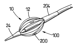
Attached to one or more of the elongate members 12 is a pressure sensor 200 in
the form of a strain gauge mounted on a flexible elongate member 12. The
strain
gauge may be defined within the elongate member 12 by means of one or more
cuts 202 as shown in Figure 11. The cuts 202 serve to isolate the strain gauge
thus
allowing pressure measurements to be taken within a tubular anatomy that are
substantially independent of any pressure exerted on the device in order to
maintain the device in an expanded state.
The device shown in Figures 9 and 10 comprises an active element 100 having a
length in a collapsed state of approximately 100mm. The diameter of the active
element in the collapsed state is approximately 12mm, and in the expanded
state is
approximately 30mm.
The device could, however, have desirable dimensions. For example, the active
element could have a diameter of approximately 3mm in the collapsed state.
The device 12 further comprises a front cone 24 and a tail cone 204 both of
which
are formed from a flexible material in order to allow the device to be able to
pass
down a tubular anatomy such as the oesophagus. The length of the tail cone 204
is approximately 20mm, and the total length of a tail portion 205 connecting
the
device to a display unit, for example, is approximately 400mm.
-13-
CA 02623347 2008-03-20
WO 2007/034203 PCT/GB2006/003533
The dimensions of the device 9 are shown graphically in Figure 10. It is to be
understood however that the device according to the present invention could
have
any desirably dimensions.
The pressure sensor could have a number of different configurations as shown
in
Figure 12a which shows a pressure sensor 200 mounted on a flexible element 12.
The pressure sensor may be orientated appropriately to measure the expected
pressures within the tubular anatomy.
For example, as shown in Figure 12c, the pressure sensor 200 may be orientated
so that the direction of strain sensing is orthogonal to the direction of
strain in the
flexible member 12.
As shown in Figures 12d, 12e, 12f and 12h, the strain gauge 200 may protrude
from the structural member to ensure that the sensor touches the wall of the
tubular anatomy when the device is in situ within the anatomy.
As shown in Figures 12e, 12g and 12h, the strain gauge 200 may be etched so
that
it has a thickness that is less than the thickness of the flexible member 12
on
which it is mounted. This results in a greater sensitivity of the pressure
sensor. -
Referring now to Figures 13a to 13e, further embodiments of a device 10 are
illustrated schematically.
Figure 13a is a schematic representation of the device of Figure 9.
Figure 13b is a schematic representation of a device 10 comprising two
flexible
portions 110 attached together. The flexible portions 110 may be attached
together in a modular manner, and any number of flexible portions 110 may be
so
attached.
-14-
CA 02623347 2008-03-20
WO 2007/034203 PCT/GB2006/003533
In Figure 13c, a device 10 is illustrated in which the flexible portion 110 is
encased within a passive outer shell 204. The flexible portion is used to
expand
the device 10, and the presence of the passive outer shell 204 provides
additional
structural strength to the device 10. The outer shell may be formed from any
suitable material such as metal, rubber or plastic.
Figure 13d illustrates a device 10 having an outer casing 206 which results in
linear expansion of the device 10.
Figure 13e represents schematically a device 10 comprising a flexible portion
formed from a balloon 208.
Turning now to Figure 14, the components used to form the flexible elements of
the device 10 shown in Figure 9 are illustrated schematically.
When the device 10 forms part of an existing device such a flexible fibre
optic
endoscope, the endoscope may be positioned within a oesophagus in order to
view
a stricture. The device 10 may then be passed through an operative channel in
the
endoscope and positioned at the site of the stricture. The device may then be
expanded to dilate the stricture.
The device may of course be used in any other desirable way.
-15-