Note: Descriptions are shown in the official language in which they were submitted.
CA 02623399 2013-02-05
ONE PIECE SEALING RESERVOIR FOR AN INSULIN INFUSION PUMP
Field of the Invention
Fluid reservoirs for use in conjunction with insulin pumps, namely, one-piece
fluid
reservoirs that include a male luer fitting and can seal to a housing of the
insulin pump.
Background
Infusion pumps are provided for diabetic patients to allow for the infusion
into the
body of the patient of a regulated amount of insulin or other medication.
Existing pumps
provide a piston for acting on a fluid reservoir and for urging fluid, such as
insulin, from the
reservoir through a conduit to an infusion set and into a patient.
Some of the existing infusion pumps, such as that illustrated in U.S. Patent
No.
6,248,093 (which may be referred to for details), have an 0-ring or other
means for
providing waterproof or water resistant sealing between the fluid reservoir,
insertable into the
pump, and the pump housing. By providing a waterproof or water resistant
engagement
between an insertable fluid reservoir and the housing, the pump user may
engage in activities,
such as showering or other behaviour that will subject the pump to water. It
can be
appreciated that the pump and reservoir combination would, advantageously, be
water
resistant.
1
CA 02623399 2008-03-20
WO 2007/037979
PCT/US2006/035515
Currently, fluid reservoirs that are used with water resistant pumps
have a septum sealed reservoir or a luer nosed reservoir. A reservoir having
a septum requires engagement with a piercing member to pierce the septum
and provide fluid to a conduit for delivery to an infusion pump. The current
reservoirs having a male luer fitting integral therewith, require a separate
piece, engageable to the fluid reservoir for adapting the fluid reservoir to
the
water resistant pump. Thus, both of the current types described need a
separate piece, either with or without a piercing member, to adapt the fluid
reservoir in water sealing relation to the pump housing. While there are some
advantages to this arrangement, Applicants have found advantages in
providing in a single piece, integral unit, a fluid reservoir with a male luer
fitting
at a removed end thereof, which one-piece reservoir is adapted to fit in water
sealing relation to an opening in a pump housing.
It is more convenient for a consumer to use with a single piece rather
than having to engage one piece (an adaptor) to another (a fluid reservoir)
and then the combined assembly to a pump housing. Further, there are some
advantages in the manufacturing process for providing a single piece of
Applicants' novel design. Further, advantages result from Applicants' use of a
single piece design, combined with a luer fitting, which luer fitting can be
adapted to receive a needle for removing fluid from a larger insulin
container,
which same luer fitting may subsequently, after the reservoir is engaged with
the pump, accept a common female lure fitting attached to a conduit having
an insulin set at the removed end thereof.
Applicants provide a novel one-piece fluid reservoir for engagement
with an infusion pump, which one-piece fluid reservoir will achieve, in a
single
2
CA 02623399 2013-02-05
unitary piece, a number of functions. Some of these functions, achieved in a
one-piece fluid
reservoir engageable with an infusion pump, and the associated structure
include the
following:
SUMMARY OF THE INVENTION
In a broad aspect, the invention pertains to a fluid reservoir assembly for
engaging a
pump, the pump having a housing, a reservoir chamber, a threaded, cylindrical
reservoir
housing chamber opening having a sealing member, and a piston to act on the
fluid reservoir
assembly when the fluid reservoir assembly is in the reservoir chamber. The
fluid reservoir
assembly comprises a one-piece barrel, the one-piece barrel including a
cylindrical barrel
portion having a barrel diameter and having a first open end and a second end,
and a male
luer fitting integral with the second end of the barrel portion, the male luer
fitting having an
opening at a removed end thereof. The one-piece barrel includes a neck portion
integral with
the barrel portion. The neck portion includes integral threads dimensioned to
engage the
threads of the reservoir housing chamber opening. The one piece-barrel
includes a cylindrical
sealing surface radially outward of the neck portion threads and configured to
lay adjacent the
interior of the reservoir housing chamber opening of the pump housing and
engage the sealing
member, the cylindrical sealing surface being integral with the neck. A
plunger is
dimensioned for slideable receipt into the open end of the one-piece barrel.
In a further aspect, the invention provides a kit for providing insulin to a
patient
through an infusion set engaged with the patient. The kit comprises a fluid
reservoir
assembly comprising a one-piece barrel, the one-piece barrel including a
cylindrical barrel
portion having a barrel diameter and having a first open end and a second end.
A male luer
fitting is integral with the second end of the barrel portion, the male luer
fitting having an
opening at a removed end thereof. The one piece barrel includes a neck portion
integral with
the barrel portion, the neck portion including integral threads dimensioned to
engage the
threads of a reservoir housing chamber opening. The one piece barrel includes
a cylindrical
sealing surface radially outward of the neck portion threads and is configured
to lay adjacent
the interior of the reservoir housing chamber opening of the pump housing and
engage a
3
CA 02623399 2013-02-05
sealing member in the reservoir housing chamber opening, the cylindrical
sealing surface
being integral with the neck. A plunger is dimensioned for slidable receipt
into the open end
of the one-piece barrel. There is a rod for engaging the plunger, and a
container has insulin
therein, the container including a sealing septum. A needle assembly has a
female luer fitting
and a needle dimensioned to puncture the sealing septum of the container, and
a pump has a
reservoir chamber and a reservoir chamber opening, the reservoir chamber
opening with the
sealing member therein.
In a still further aspect, the invention provides an assembly for the delivery
of insulin
to a diabetic patient, the assembly comprising a pump, the pump having a
reservoir chamber,
a drive piston, and a threaded reservoir chamber opening with a sealing
member, and a fluid
reservoir. There is a one-piece barrel, the one-piece barrel including a
cylindrical barrel
portion having a barrel diameter and having a first open end and a second end.
A male luer
fitting is integral with the second end of the barrel portion, the male luer
fitting having an
opening at a removed end thereof. The one-piece barrel includes a neck portion
integral with
the barrel portion, the neck portion including integral threads dimensioned to
engage the
threads of the reservoir housing chamber opening. The one-piece barrel
includes a cylindrical
sealing surface radially outward of the neck portion threads and configured to
lay adjacent the
reservoir housing chamber opening of the pump housing and engaging the sealing
member,
the cylindrical sealing surface being integral with the neck.
These and other aspects are provided in a fluid reservoir assembly for
engaging a
fluid pump, the pump having a housing, a fluid reservoir chamber, a threaded,
cylindrical
reservoir housing chamber opening, and a piston to act on the fluid reservoir
assembly when
the fluid reservoir is in the reservoir chamber, the fluid reservoir assembly
comprising a one-
piece barrel assembly, the one-piece barrel assembly including a cylindrical
barrel portion
having a barrel diameter and having a first open end and a second end, a male
luer fitting
integral with the second end of the barrel portion, the male luer fitting
having an opening at a
removed end thereof, the one piece barrel assembly including a neck portion
integral with the
3a
CA 02623399 2013-02-05
barrel portion, the neck portion including threads dimensioned to engage the
threads of the
reservoir housing chamber opening, the one piece barrel assembly including a
cylindrical
sealing surface dimensioned to lay adjacent the reservoir housing chamber
opening of the
pump housing in fluid sealing relation, the cylindrical sealing surface
integral with the neck,
and a plunger dimensioned for slideable receipt into the open end of the one-
piece barrel
assembly.
1. Thread segments to engage the female threads in the housing or case of the
infusion pump to hold the fluid reservoir in place;
2. A sealing surface to seal to the 0-ring in the case of the infusion pump to
help
seal out water;
3b
CA 02623399 2008-03-20
WO 2007/037979
PCT/US2006/035515
3. Detents to releasably and lockingly engage recesses in the case of the
infusion pump to prevent accidental unscrewing of the fluid reservoir;
4. Vent port(s) to permit pressure in the housing or case of the infusion
pump to adjust to the external atmosphere;
5. A small orifice opening in the luer end of the reservoir to allow flow of
medication from the reservoir while providing adequate resistance to
flow so that the pump can sense, the flow of medication and
measure the quantity of medication delivered;
6. Tabs to assist in holding the reservoir while screwing it into the pump;
and
7. A plunger and rod with threads adapted to prevent the rod from
becoming stuck in the plunger and thus difficult to remove after
filling the
reservoir.
The one-piece sealing reservoir typically provides a 1.8 ml, 3.0 ml or
other capacity reservoir intended for use in a portable infusion pump used for
delivery of medication, such as insulin. The fluid reservoir provides a common
male luer connection which allows the patient using the infusion pump to
connect it to their choice of infusion delivery devices that have a female
luer
receptacle.
BRIEF DESCRIPTION OF THE DRAWINGS
Fig. 1 illustrates an exploded view of applicants' novel one-piece fluid
reservoir assembly which may also contain a plunger engagement rod, in
perspective view.
4
CA 02623399 2008-03-20
WO 2007/037979
PCT/US2006/035515
Fig. 2 illustrates applicants' novel fluid reservoir, including the fluid
reservoir assembly with the plunger rod engaging the plunger thereof, in
cross-section elevational view.
Fig. 3 illustrates a close-up detail view, in perspective, of the second
end of the barrel portion showing the integral neck sealing surface, tabs,
threads and other related structure, including the male luer fitting in fluid
engagement with the interior of the barrel.
Fig. 4 is a similar perspective view of the assembly of Fig. 3, taken
from a different angle.
Fig. 5 is a perspective view from the front of applicants' barrel portion
of the fluid reservoir assembly showing the vent ports integral therewith and
the filter medium bonded or sealed to the external walls of the ports.
Fig. 6 shows the plunger with an internal threaded area and the rod
with the threaded area for threadable engagement with the plunger,
illustrating the novel flat ends of the threads in cross-sectional view.
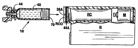
Fig. 7 is a cross-sectional elevational view, partially cut away, showing
the manner in which applicants' fluid reservoir assembly engages a housing of
a pump having the reservoir chamber and a reservoir chamber opening.
Fig. 8 illustrates the manner in which applicants' fluid assembly may be
used to fill an empty fluid reservoir for insertion into the fluid pump.
Fig. 9 illustrates in a top elevational view, partially cut away, the
manner in which applicants' fluid reservoir assembly engages the reservoir
chamber of the housing of the pump.
Fig. 10 illustrates in a side elevational view, applicants' novel
pump/infusion set assembly wherein the fluid reservoir engages the pump and
5
CA 02623399 2013-02-05
an infusion set having a conduit with a female luer fitting at the end thereof
to
engage the male luer fitting of the fluid reservoir.
DETAILED DESCRIPTION OF THE PREFERRED EMBODIMENTS
Fig. 1 shows a fluid reservoir assembly 10 with a luer portion 20, a
neck portion 40, and a barrel portion 60. A plunger 70 slideably engages the
inner surface of the barrel portion, and a plunger engagement rod 90
removably engages the plunger. The barrel portion 60 holds the medication to
be delivered and receives the plunger, which will mate with a drive piston
from
the infusion pump (see Fig. 9).
Fig. 2 shows the assembled reservoir 10, plunger 70 and rod 90 in
cross section. The plunger 70 has a plunger threaded area 72 to engage with
a rod thread area 94 of the rod 90. The plunger typically is adapted to
receive
one or more 0-rings 74 on an outer surface thereof to slideably seal to the
barrel portion 60 of the reservoir assembly 10.
During filling of the reservoir 10 illustrated in Fig. 8, a handle 92 of the
rod 90 in used to draw the plunger 70 back and suck medication from a larger,
typically septum sealed, container 106 into the barrel area 60. After filling
the
reservoir 10, the rod 90 is unscrewed from the plunger 70 and discarded.
Fig. 3 shows details of the luer area 20 and neck area 40. The luer
area 20 consists of a standard male luer 22, and optionally threads 26 to
receive a threaded female luer receptaale from an infusion delivery set. The
standard male luer and associated structure (threads, etc.) may be
dimensioned according to IS0594-1 and 594-2 (which may be referred to for
further details), provided, however, the opening dimensions as set forth
below.
6
CA 02623399 2008-03-20
WO 2007/037979
PCT/US2006/035515
The filled reservoir 10 is inserted, axially, into the infusion pump, barrel
end first after removal of the rod 90. When the reservoir 10 is fully inserted
into the infusion pump, the thread segments 44 located on the neck 42
engage threads in the infusion pump. Optionally, tabs 24 are provided to
facilitate the tightening and loosening of the reservoir in the infusion pump.
Sealing surface 30 is dimensioned slightly less than the reservoir chamber
opening assembly to seal the reservoir 10 to an 0-ring (or 0-rings) or other
functional equivalents located in the infusion pump housing opening (see Fig.
9). The sealing of the reservoir to the case housing of the infusion pump
provides a watertight or water resistant infusion pump/reservoir assembly
permitting the patient to wear the infusion pump during swimming, showering
or other activities which might otherwise cause water to enter the case and
damage the electronic components. Detents 28 may engage recesses in the
infusion pump case to prevent accidental unscrewing of the reservoir from the
infusion pump. Detents 28 may be integral with the walls of sealing surface
30.
Existing infusion pumps have a means of measuring the volume of
medication flowing from the fluid reservoir by determining motion of the drive
piston. They sometimes use a sensor located in the drive piston assembly to
detect the movement of the plunger in the reservoir. For the sensor to detect
the movement of the drive piston, there must be resistance to the flow of
medication and hence to the movement of the plunger. Luer 22 has a novel
orifice opening 32 which allows medication to flow from the reservoir while
providing resistance to the flow. The size of the orifice opening 32 is novel
as
being very small, from 0.003" to 0.020" (preferred range .005-.010") in
7
CA 02623399 2008-03-20
WO 2007/037979
PCT/US2006/035515
diameter. This small diameter of the orifice opening 32 provides a restriction
to flow sufficient for the infusion pump to measure the quantity of medication
delivered.
Fig 4 is a view of the luer area 20 showing at least one vent port 34.
Fig. 5 shows a filter medium 36, typically hydrophobic, bonded into the
vent port 34. While the infusion pump/reservoir assembly is sealed to prevent
water from entering the interior of the case, there should be structure
provided
to let the internal pressure in the case adjust to the external atmosphere. If
the
internal pressure in the infusion pump is different from the external
atmosphere, the accuracy of medication dosing may be effected. To allow the
internal pressure of the infusion pump to adjust to the external atmosphere,
vent ports 34 are provided in luer area 20 of reservoir 10. Vent ports 34 are
covered typically by a hydrophobic filter material 36. Hydrophobic material
permits gas to pass through the material while resisting the passage of water
or other liquids, thus permitting water resistant venting. The hydrophobic
material may be welded to the reservoir by ultrasonic or heat staking or it
may
be bonded by other means.
Fig. 6 shows thread area 72 of plunger 70 and thread area 94 of rod
90. The threads 72 of the plunger 70 end in a flat end 76. The threads 94 of
the rod 90 also end in a similarly dimensioned flat end 98. When the rod 90 is
screwed into the plunger 70, the flat ends 76 and 98 butt against each other
before threads 72 and 94 can tighten against one another. Stopping the
threads in this manner prevents the rod 90 from becoming stuck in the
plunger 70 and difficult to remove after filling the reservoir 10.
8
CA 02623399 2008-03-20
WO 2007/037979
PCT/US2006/035515
Fig. 7 shows an exploded view of applicants' novel fluid reservoir 10,
after the rod has been removed therefrom and after it has been filled, as it
engages the housing H of a pump.
Housing H is seen to include a reservoir chamber RC and a reservoir
chamber opening RCO. The reservoir chamber opening has detent openings
28A on the walls thereof for receipt of applicants' detents 28. Threads 44,
typically in the neck area of the fluid reservoir, are provided to engage
threads
44A on the reservoir chamber opening so as to position the fluid-filled fluid
assembly 10 within the reservoir chamber. A motor M can drive a drive piston
DP axially along the longitudinal axis of the barrel portion 60 so as to
engage
the piston and drive fluid out of the luer fitting and into a conduit 110 as
set
forth in Fig. 10.
Fig. 8 illustrates the use of applicant's fluid reservoir assembly to
engage a needle assembly 100, which needle assembly has engaged
therewith in fluid sealing relation a needle 102. Needle 102 has a removed
end with a small orifice in it and is hollow. Needle assembly 100 typically
includes a female luer fitting 104, which female luer fitting is designed to
and
dimensioned to be received snugly in fluid sealing relation to male luer
portion
of barrel portion of reservoir 10.
20 With the fluid reservoir 10 having needle assembly 100 engaged
therewith and, with plunger engagement rod 90 engaged with plunger 70, and
plunger 70 in a full forward position against the walls defining the end of
the
luer barrel portion 60 (which contains male luer portion 20), user can insert
needle 102 through a septum of a fluid (typically insulin) container 106.
Retraction of plunger engagement rod 90 in the direction indicated in Fig. 8
9
CA 02623399 2008-03-20
WO 2007/037979
PCT/US2006/035515
will allow fluid to be withdrawn from container 106 into fluid reservoir 10.
When plunger 70 is at or near the removed open end of barrel portion 60,
plunger engagement rod 90 can be rotated and removed from the plunger.
Because of applicant's novel flat-end-to-flat-end threaded engagement
between plunger engagement rod 90 and plunger 70, plunger 70 should not
rotate in the barrel and thus will make rotational disengagement of plunger
from the rod easy. With plunger engagement rod 90 discarded, reservoir 10
can be asserted axially into cylindrical pump as illustrated in Figs. 7 and 9.
Applicant's novel reservoir has a barrel portion, typically of a diameter
sufficient to pass through reservoir chamber opening and into the reservoir
chamber, aligning with the walls of the chamber so as to present a barrel
assembly longitudinal axis aligned with the longitudinal axis of the drive
piston. When applicant's reservoir 10 is inserted into housing H, such as a
Mini-Med Model MMT-511, threads 44A will engage threads 44 of reservoir
10, and upon engagement and continued rotation of reservoir 10, the
reservoir will be drawn into reservoir chamber RC a distance to place sealing
surface 30 adjacent 0-rings or other sealing means at reservoir chamber
opening RCO. Moreover, applicant's detents 28 on the walls of sealing
surface 30, typically small projections, may engage cutouts 28A in the walls
of
reservoir chamber opening RCO as illustrated in Fig. 7.
Fig. 10 shows pump P held in place by a belt B on a user. Pump P
shows an infusion set assembly 110 having a fluid conduit 112 engaged
therewith. At a near end of the fluid conduit 112 is a female luer fitting 114
for
snugly engaging applicant's fluid reservoir 10. A female luer assembly 114
may have threads 114A at a base thereof for threaded engagement with luer
CA 02623399 2008-03-20
WO 2007/037979
PCT/US2006/035515
threads 26 of fluid reservoir 10. Fluid from the fluid reservoir 10 will be
urged,
by incremental advances of drive piston DP, through the male and female luer
fittings and conduit 112 to an infusion set 116 for infusion into the body of
the
user in ways known in the trade.
Although the invention has been described with reference to specific
embodiments, this description is not meant to be construed in a limited sense.
Various modifications of the disclosed embodiments, as well as alternative
embodiments of the inventions, will become apparent to persons skilled in the
art upon the reference to the description of the invention. It is, therefore,
contemplated that the appended claims will cover such modifications that fall
within the scope of the invention.
11