Note: Descriptions are shown in the official language in which they were submitted.
CA 02623616 2008-03-25
WO 2007/064739 PCT/US2006/045752
MRI-GUIDED LOCALIZATION AND/OR LEAD PLACEMENT SYSTEMS,
RELATED METHODS, DEVICES AND COMPUTER PROGRAM
PRODUCTS
RELATED APPLICATION
This application claims the benefit of priority to U.S. Provisional
Application
Serial No. 60/740,353, filed November 29, 2005, the contents of which are
hereby
incorporated by reference as if recited in full herein.
FIELD OF THE INVENTION
The present invention relates to placement/localization of interventional
medical devices and/or therapies in the body. Embodiments of the present
invention
may be particularly suitable for placing neuro-modulation leads, such as Deep
Brain
Stimulation ("DBS") leads, implantable parasympathetic or sympathetic nerve
chain
leads and/or CNS stimulation leads.
BACKGROUND OF THE INVENTION
Deep Brain Stimulation (DBS) is becoming an acceptable therapeutic
modality in neurosurgical treatment of patients suffering from chronic pain,
Parkinson's disease or seizure, and other medical conditions. Other electro-
stimulation therapies have also been carried out or proposed using internal
stimulation
of the sympathetic nerve chain and/or spinal cord, etc.
One example of a prior art DBS system is the Activa system from
Medtronic, Inc. The Activa system includes an implantable pulse generator
stimulator that is positioned in the chest cavity of the patient and a lead
with axially
spaced apart electrodes that is implanted with the electrodes disposed in
neural tissue.
The lead is tiuzneled subsurface from the brain to the chest cavity connecting
the
electrodes with the pulse generator. These leads can have multiple exposed
electrodes
at the distal end that are connected to conductors which run along the length
of the
lead and connect to the pulse generator placed in the chest cavity.
MRI is an imaging modality that can be used to evaluate cardiac, neurological
and/or other disorders. It may be desirable to use MRI for patients with
implanted
I
CA 02623616 2008-03-25
WO 2007/064739 PCT/US2006/045752
stimulation devices and leads. However, currently available lead systems may
be
unsuitable to use in a magnetic resonance imaging (MRI) environment. For
example,
the devices may not be MRI compatible, i.e., they may contain ferromagnetic
materials, which may distort the MRI images. Also, currently available
lead/probe/cable systems may be susceptible to unwanted induced RF and/or AC
current and/or localized heating of the tissue. For example, the Medtronic
ActivaC
device typically recommends that MRI imaging be carried out in a 1.5T magnet
without using body coils, f. e., only using head coils for transmission of the
RF
excitation pulse(s). Also, the problem of unwanted RF deposition may increase
as
higher magnetic fields, such as 3T systems, become more common for MRI imaging
(the RF pulses having shorter wavelengths).
It is believed that the clinical outcome of certain medical procedures,
particularly those using DBS, may depend on the precise location of the
electrodes
that are in contact with the tissue of interest. For example, to treat
Parkinson's
tremor, presently the DBS probes are placed in neural tissue with the
electrodes
transmitting a signal to the thalamus region of the brain. DBS stimulation
leads are
conventionally implanted during a stereotactic surgery, based on pre-operative
MRI
and CT images. These procedures can be long in duration and may have reduced
efficacy as it has been reported that, in about 30% of the patients implanted
with these
devices, the clinical efficacy of the device/procedure is less than optimum.
Notwithstanding the above, there remains a need for alternative interventional
tools.
SUMMARY OF EMBODIMENTS OF THE INVENTION
Embodiments of the present invention are directed to medical tools, systems
and methods useful for MRI-guided localization and/or placement of
interventional
therapies and/or devices.
Some embodiments of the present invention provide systems that utilize at
least one MRI to visualize (and/or locate) a therapeutic region of interest
(such as, for
example, a target site inside the brain) and utilize at least one MRI to
visualize (and/or
locate) an interventional tool or tools that are used to deliver a therapy
and/or to place
a chronically (typically permanently) implantable device that will deliver a
therapy.
Some einbodiments include a targeting cannula with a lumen sized and
configured to slidably receive an elongate probe. The elongate probe can
include a
2
CA 02623616 2008-03-25
WO 2007/064739 PCT/US2006/045752
recording electrode (e.g., transducer) and/or a stimulation electrode.
Optionally, the
targeting cannula and/or probe or components thereof may be MRI visible.
Some embodiments of the present invention can be used to place
interventional lead systems in the body. The lead placement systems can be
configured to both collect MRI and/or NMR data and sense local signals (e.g.,
EEG
signals) and may also or alternatively be configured to stimulate local (e.g.,
neural)
tissue. The lead placement system, may be used to place implantable deep brain
stimulation leads. The lead placement systems may also be configured to place
implantable cardiac interventional leads or devices.
The lead placement system can include a probe and/or sheath that can be
relatively long, having a length in the body of greater than 10 cm, or may
have a
lesser length, such as between about 3-6 cm. The probe and/or lead can hold
one or a
plurality of electrodes and/or at least one may be a recording electrode. The
probe
may hold a recording and a stimulating electrode. The probe and/ or sheath can
be
MRI active (include MRI imaging coils and/or cooperate with other components
to
define an MRI antenna).
In some embodiments, the electrodes and stimulation control module can be
configured to generate different stimulation field patterns having different
size and
shape stimulation volumes and different directional stimulation volumes and
the
patient data analysis module may be configured to automatically determine an
optimal
location of an electrode for DBS for a particular patient.
Still other embodiments are directed to systems for MRI guided placement of
deep brain stimulation leads. The systems include a translatable targeting
cannula, a
frameless mount configured to hold the targeting cannula, and an MRI antenna
with
transducer configured to releasably engage the targeting cannula. The cannula
may be
configured to be inserted into a burr hole placed in a patient's skull and the
stimulation
probe and MRI antenna and stimulation probe may be configured for deep brain
placement guided through the cannula.
Some embodiments are directed to MRI compatible localization and/or
guidance systems for facilitating placement of an interventional device in
vivo. The
systems include: (a) a mount having a base with a patient access aperture
adapted for
fixation to a patient, wherein an upper portion of the mount is able to
controllably
translate with at least two degrees of freedom; (b) a targeting cannula having
at least
one axially extending lumen configured to attach to the mount; and (c) an
elongate
3
CA 02623616 2008-03-25
WO 2007/064739 PCT/US2006/045752
probe configured to snugly slidably advance and retract in one of the at least
one
axially extending lumen of the targeting cannula, the elongate probe
comprising at
least one of a recording electrode or a stimulation electrode. In operation,
the mount
can be adjusted to provide a desired internal access path trajectory to a
target location.
Some embodiments are directed to MRI compatible localization and/or
guidance systems for facilitating placement of an interventional device in
vivo. The
systems include: (a) a mount having a receiving port and a base with an access
aperture adapted for fixation to a patient, the mount port configured to
translate with
at least two degrees of freedom; (b) a targeting cannula having at least one
axially-
extending lumen configured to reside in the port; and (c) an elongate probe
configured
to define an MRI antenna configured to snugly slidably advance and retract in
one of
the at least one axially extending lumen of the targeting cannula. In
operation, the
targeting cannula can be positionally adjusted in the mount to provide a
desired
internal access path trajectory through the mount access aperture to a target
location.
Some embodiments are directed to MRI interventional tools that include: (a) a
cannula with a through lumen and at least one axially extending closed fluid
filled
lumen or channel; and (b) a first multipurpose probe configured to slidably
extend
through the lumen of the cannula.
Some embodiments are directed to MRI-compatible interventional tools that
include: (a) a frameless mount; (b) a multi-lumen insert configured to mount
to the
frameless mount; and (c) an MRI visible targeting cannula with a closed
perimeter
configured to slidably reside in one lumen of the multilumen insert when the
insert is
mounted to the frameless mount.
Other embodiments are directed to MRI interventional or placement tools that
include: (a) a mount having a patient access aperture configured to mount to a
patient;
(b) an elongate delivery sheath extendable from through the access aperture of
the
mount to a target access location in the patient; and (c) a fluid filled tube
configured
to slidably advance with and retract from the sheath.
Still other embodiments are directed to MRI guided localization systems. The
systems include: (a) a base with an in vivo access aperture configured to
mount to a
patient; (b) a translatable mount member attached to the base, the
translatable member
configured to translate about a pivot point extending proximate the base
access
aperture, the translatable member having a receiving port configured to
receive at
least one of a targeting cannula or a multi-lumen insert; (c) a plurality of
sensors in
4
CA 02623616 2008-03-25
WO 2007/064739 PCT/US2006/045752
communication with at least one of the base and translatable member whereby
the
sensors define positional data of the mount member; (d) a drive system in
communication with the translatable mount member; and (e) a control circuit in
communication with the drive system configured to direct the translatable
member to
translate to defme a desired trajectory orientation.
Some embodiments are directed to automated trajectory adjustment systems.
The systems include: (a) a mount member with a base having an access aperture
therethrough configured to reside against a mounting surface of a patient; (b)
an MRI -
visible elongate member configured to mount to the mount member; (c) at least
one
position sensor in communication with the mount member; (d) a drive system in
communication with the mount member; and (e) a control circuit in
communication
with the drive system configured to identify adjustments to alter the position
of the
mount member to obtain a desired trajectory of an access path through the
access
aperture into the patient.
Other embodiments are directed to systems for MRI guided localization of
therapies/tools. The systems include: (a) an MRI visible elongate member; and
(b) a
localization system in communication with a MRI scanner configured to
programmatically determine a scan plane location of the elongate member having
a
first trajectory in 3D MRI space whereby the elongate member acts as an MRI
detectable marker.
Still other embodiments are directed to methods for automatically defining a
scan plane associated with an elongate MRI visible marker. The methods include
programmatically determining a scan plane location of an MRI visible elongate
member held in a mount affixed to a patient and residing in 3D MRI space with
an
associated first trajectory.
Some embodiments are directed to frameless head mounts for MRI
interventional procedures. The mounts include: (a) a base having a patient
access
aperture configured to affix to a burr hole in a skull of a patient; (b) a
rotatable
platform attached to the base; and (c) a pair of spaced apart upwardly
extending arms
holding a receiving port, the receiving port being able to translate in
response to
translation of the arms.
The frameless mount may optionally also include respective non-
ferromagnetic flexible drive cables attached to the rotation and pitch
adjustment
members to allow a user to adjust an access path trajectory while the user
resides
5
CA 02623616 2008-03-25
WO 2007/064739 PCT/US2006/045752
proximate but outside an end of a bore of a magnet associated with an MRI
scanner
without moving the patient. The mount may also optionally include an automated
trajectory adjustment circuit in communication with the adjustment members
whereby
the receiving port is automatically moved to a desired position based on MRI
data.
Another aspect of the invention relates to methods of adjusting a trajectory
of
a head mount defining an internal access path trajectory during an MRI-guided
interventional procedure. The method includes: (a) affixing a head mount with
a
holding member having adjustable pitch and rotation to a head of a patient; -
and (b)
adjusting at least one of pitch or rotation of the holding member to defme a
desired
access path trajectory into the patient while the patient remains in position
in a bore of
a magnet.
Although described above with respect to method aspects of the present
invention, it will be understood that the present invention may also be
embodied as
systems and computer program products.
Other systems, methods, and/or computer program products according to
embodiments of the invention will be or become apparent to one with skill in
the art
upon review of the following drawings and detailed description. It is intended
that all
such additional systems, methods, andlor computer program products be included
within this description, be within the scope of the present invention, and be
protected
by the accompanying claims.
These and other embodiments will be described further below.
BRIEF DESCRIPTION OF THE DRAWINGS
Figure lA is a schematic illustration of a MRI guided localization system
according to embodiments of the present invention.
Figure 1B is a schematic partial side view illustration of a targeting cannula
and probe according to some embodiments of the invention.
Figure 1C is a partial side view illustration of a different targeting cannula
configuration and a different probe configuration according to embodiments of
the
invention.
Figure 2A is a partial side view illustration of a device with a retractable
sheath according to embodiments of the invention.
6
CA 02623616 2008-03-25
WO 2007/064739 PCT/US2006/045752
Figure 2B a partial side view illustration of the device shown in Figure 2A
illustrating the sheath remaining in position as the probe is retracted
according to
embodiments of the invention.
Figure 2C is a schematic partial top view of a probe and sheath shown in
Figure 2A illustrating visual indicia of movement according to embodiments of
the
present invention.
Figure 2D is a sectional view of the probe and sheath shown in Figure 2C
according-to embodiments of the present invention.
Figure 2E is a side view of the sheath acting as a targeting cannula in
combination with a fluid filled or MRI visible tube according to some
embodiments
of the invention.
Figure 3A is a side view of a stimulation lead according to embodiments of
the present invention.
Figure 3B is a section view of the device shown in Figure 3A, taken along
line 3B-3B.
Figure 3C is an electrical schematic diagram of the device shown in Figure
3A according to embodiments of the present invention.
Figure 4A is a schematic illustration of a long lead with a plurality of
axially
spaced apart RF traps along a length of a conductor or lead according to
embodiments
of the invention.
Figure 4B is a schematic illustration of a lead system with RF traps having co-
wound conductors in a common shield according to embodiments of the invention.
Figure 5 is a block diagram of a bimodal lead operating circuit according to
embodiments of the present invention.
Figure 6 is a block diagram of another operating circuit according to
embodiments of the present invention.
Figure 7A is a schematic illustration of a splitter circuit according to
embodiments of the present invention.
Figure 7B is an end view of the circuit shown in Figure 7A.
Figure 8 is a schematic illustration of a localization system according to
embodiments of the invention.
Figure 9 is a flow chart of operations that can be used to carry out
embodiments of the invention.
7
CA 02623616 2008-03-25
WO 2007/064739 PCT/US2006/045752
Figure 10A is a greatly enlarged side view of a frameless mount according to
embodiments of the invention.
Figure lOB is a greatly enlarged side view of a frameless mount similar to
that
shown in Figure 10A, illustrating pitch and rotation adjustment members
according to
embodiments of the invention.
Figure 10C is a greatly enlarged front perspective view of the device shown
in Figure lOB.
Figure 10D is a greatly enlarged side perspective view of the device shown in
Figure 10B.
Figure 10E is a greatly enlarged front view of a different configuration of
the
device shown in Figure lOB according to embodiments of the invention.
Figures 11A-11F illustrate different configurations of the frameless mount
shown in Figure 10A.
Figure 12A is a perspective side view of a multi-lumen insert that can be held
by a mount according to embodiments of the invention.
Figure 12B is a side view, Figure 12C and 12D are end views and Figure
12E is a side view (with the top facing down) of the device shown in Figure
12A.
Figure 13A is a side perspective view of the mount shown in Figure 12A with
the multi-lumen insert shown in Figure 12A according to some embodiments of
the
invention. Figures 13B and 13C are side and front views thereof.
Figure 14 is a partially transparent side view of a targeting cannula with a
through Iumen and a fluid filled axially extending segment according to
embodiments
of the invention.
Figure 15A is a schematic side view of a targeting cannula with a fluid filled
chamber that can reside in a lumen of a multi-lumen insert such as that shown
in
Figure 12A.
Figure 15B is a side schematic view of the targeting cannula shown in Figure
15A alternately configured with an axially extending side arm according to
some
embodiments of the invention.
Figure 16A is a schematic illustration of a visualization of trajectory lines
in
an oblique coronal/sagittal image extending from different lumens to a target
site
according to some embodiments of the invention.
Figure 16B is a schematic illustration of the trajectory lines as they
intersect
the target site in an axial/oblique scan according to embodiments of the
invention.
8
CA 02623616 2008-03-25
WO 2007/064739 PCT/US2006/045752
Figures 17A-17C are schematic illustrations of steps that can be taken to
place a site-specific interventional device or therapy according to some
embodiments
of the invention.
Figures 18A-18E are schematic illustration of additional steps that can be
taken to define a trajectory and/or place an interventional device according
to
embodiments of the invention.
Figures 19 and 20 are block diagrams of data processing systems according to
embodiments of the present invention.
DETAILED DESCRIPTION OF EMBODIMENTS OF THE INVENTION
The present invention will now be described more fully hereinafter with
reference to the accompanying drawings, in which embodiments of the invention
are
shown. This invention may, however, be embodied in many different forms and
should not be construed as limited to the embodiments set forth herein;
rather, these
embodiments are provided so that this disclosure will be thorough and
complete, and
will fully convey the scope of the invention to those skilled in the art. Like
numbers
refer to like elements throughout. It will be appreciated that although
discussed with
respect to a certain antenna embodiment, features or operation of one lead
system
embodiment can apply to others.
In the drawings, the thickness of lines, layers, features, components and/or
regions may be exaggerated for clarity and broken lines illustrate optional
features or
operations, unless specified otherwise. In addition, the sequence of
operations (or
steps) is not limited to the order presented in the claims unless specifically
indicated
otherwise. It will be understood that when a feature, such as a layer, region
or
substrate, is referred to as being "on" another feature or element, it can be
directly on
the other element or intervening elements may also be present. In contrast,
when an
element is referred to as being "directly on" another feature or element,
there are no
intervening elements present. It will also be understood that, when a feature
or
element is referred to as being "connected" or "coupled" to another feature or
element,
it can be directly connected to the other element or intervening elements may
be
present. In contrast, when a feature or element is referred to as being
"directly
connected" or "directly coupled" to another element, there are no intervening
elements
9
CA 02623616 2008-03-25
WO 2007/064739 PCT/US2006/045752
present. Although described or shown with respect to one embodiment, the
features
so described or shown can apply to other embodiments.
The terminology used herein is for the purpose of describing particular
embodiments only and is not intended to be limiting of the invention. As used
herein,
the singular forms "a", "an" and "the" are intended to include the plural
forms as well,
unless the context clearly indicates otherwise. It will be further understood
that the
terms "comprises" and/or "comprising," when used in this specification,
specify the
presence of stated features, integers, steps, operations, elements, and/or
components,
but do not preclude the presence or addition of one or more other features,
integers,
steps, operations, elements, components, and/or groups thereof. As used
herein, the
term "and/or" includes any and all combinations of one or more of the
associated
listed items. As used herein, phrases such as "between X and Y" and "between
about
X and Y" should be interpreted to include X and Y. As used herein, phrases
such as
"between about X and Y" mean "between about X and about Y." As used herein,
phrases such as "from about X to Y" mean "from about X to about Y."
The term "RF safe".means that the device, lead or probe is configured to
operate safely when exposed to normal RF signals associated with conventional
MRI
systems. The device can be configured with RF chokes, RF traps, high impedance
segments and/or other electrical circuits that allow for the RF safe operation
in MRI
environments. The device may be active or decoupled during RF transmit in an
MRI
procedure.
The term "MRI visible" means that the device is visible, directly or
indirectly,
in an MRI image. The visibility may be indicated by the increased SNR of the
MRI
signal proximate to the device (the device can act as an MRI receive antenna
to
collect signal from local tissue) and/or that the device actually generates
MRI signal
itself, such as via suitable hydro-based coatings and/or fluid (typically
aqueous
solutions) filled channels or lumens. The term "MRI compatible" means that the
so-
called system and/or component(s) is safe for use in an MRI environment and/or
can
operate as intended in an MRI environment, and, as such, if residing within
the high-
field strength region of the magnetic field, is typically made of a non-
ferromagnetic
MR.I compatible material(s) suitable to reside and/or operate in a high
magnetic field
environment. The term high-magnetic field refers to field strengths above
about 0.5
T, typically above 1.OT, and more typically between about 1.5T and l OT.
CA 02623616 2008-03-25
WO 2007/064739 PCT/US2006/045752
The term "targeting cannula" refers to an elongate device, typically having a
substantially tubular body that can be oriented to provide positional data
relevant to a
target treatment site and/or define a desired access path orientation or
trajectory. At
least portions of the targeting cannulae contemplated by embodiments of the
invention can be configured to be visible in an MRI image, thereby allowing a
clinician to visualize the location and orientation of the targeting cannula
in vivo
relative to fiducial and/or internal tissue landscape features. Thus, the term
"cannula"
-
refers to an elongate device that can be inserted into a mount that attaches
to a patient,
but does not necessarily enter the body of a patient.
The term "imaging coils" refers to a device that is configured to operate as
an
MRI receive antenna. The term "coil" with respect to imaging coils is not
limited to a
coil shape but is used generically to refer to MRI antenna configurations,
loopless,
looped, etc., as are known to those of skill in the art. The term "fluid-
filled" means
that the component includes an amount of the fluid but does not require that
the fluid
totally, or even substantially, fill the component or a space associated with
the
component. The fluid may be an aqueous solution, MR contrast agent, or any
material
that generates MRI signal.
The term "two degrees of freedom" means that the mount allows for at least
translational (swivel or tilt) and rotational movement over a fixed site,
which may be
referred to as a Remote Center of Motion (RCM).
The term "interactive" refers to a device and/or algorithm that can respond to
user input to provide an output, typically using a Graphic User Interface
(GUI). The
GUI may operate with known GUI drawing tools, such as spline inputs to define
a
target treatment site and/or trajectory to the site in an image of an MRI
visualization
of the patient on a clinician workstation display. The term "spline" refers to
free-form
curves defined with a set of control points. Drawing of a spline curve is by
placement
of these points. An open or closed spline can be selected using a spline
dialog. An
object or point can be moved by holding down an input key, such as <Shift>.
The
control points can be edited using a point editing mode where a handle to move
the
control point. For example, holding down <Control> and dragging on a handle to
alter the shape factor of that control point.
The term "programmatically" refers to operations directed and/or primarily
carried out electronically by computer program modules, code and instructions.
11
CA 02623616 2008-03-25
WO 2007/064739 PCT/US2006/045752
The term "high radiofrequency" or "high RF" refers to RF frequencies that are
at or above about 1 MHz, and includes radiofrequencies in the range of about
1MHz
to about 256 MHz. Some embodiments of the present invention configure devices
so
as to have high impedance circuit segments or a high impedance circuit at high
RF
and low impedance circuit segments or circuit at DC or low frequency (at a kHz
or
less frequency or frequency range), i. e., at frequencies used for treatment
such as
stimulation or ablation. For example, for 1.5T, 3.0T and 6.OT systems, the
respective
frequencies are 64 MHz, 128 MHz and 256 MHz. The frequencies of the different
MRI systems are well known to those of skill in the art. The devices can be
configured to have high impedance at several of the radiofrequencies
associated with
high-field magnet MRI systems, such as systems with magnets above about 1.OT,
such as about 1.OT, 1.5T, 2.0T, 3.OT, 4.OT, 5.OT, 6. OT and 9.OT, typically
between
about 1T to 15T.
The term "high impedance" means an impedance sufficiently high to inhibit,
block or eliminate flow of RF-induced current at a target frequency range(s).
The
impedance has an associated resistance and reactance as is well known to those
of
skill in the art. Some embodiments provide an impedance of at least about 300
Ohms,
typically between about 400 Ohms to about 600 Ohms, such as between about 450
Ohms to about 500 Ohms, while other embodiments provide an impedance of
between about 500 Ohms to about 1000 Ohms. Embodiments of the invention
configure lead systems that provide sufficiently high-impedance at frequencies
associated with a plurality of different conventional and future magnetic
field
strengths of MRI systems, such as at least two of 1.5T, 2.0T, 2.5T, 3.OT,
9.OT, and the
like, allow for safe use in those environments (future and reverse standard
MRI
system compatibility).
The term "tuned" means that a parallel resonant circuit with inductive and
capacitive characteristics defined by certain components and configurations
has high
impedance at one or more target frequencies, typically including one or more
MRI
operating frequencies.
The term "coiled segment" refers to a conductive lead (trace, wire or filar)
that
has a coiled configuration. The term "co-wound segments" means that the
affected
leads, conductors, wires and/or filars can be substantially concentrically
coiled at
different radii, one above the other, or concentrically coiled closely spaced
at
substantially the same diameter. The term "co-wound" is used to describe
structure
12
CA 02623616 2008-03-25
WO 2007/064739 PCT/US2006/045752
and is not limiting to how the structure is formed (i. e., the coiled segments
are not
required to be wound concurrently or together, but may be so formed). The
terms
"conductive element", "conductive lead" and "conductors" are used
interchangeably
and refer to a conductive path that connects target components (such as, for
example,
a stimulation source and an electrode) and can include one or combinations of
a
metallic trace, a wire, a flex circuit, a filar(s), or other conductive
configuration. As
such, the conductors or conductive elements include long linear and/or non-
linear
conductors that can be formed with one or more of discrete wires, flex
circuits, filars
(bi, quadra or other winding), or by plating, etching, deposition, or other
fabrication
methods for forming conductive electrical paths.
Unless otherwise defined, all terms (including technical and scientific terms)
used herein have the same meaning as commonly understood by one of ordinary
skill
in the art to which this invention belongs. It will be further understood that
terms,
such as those defined in commonly used dictionaries, should be interpreted as
having
a meaning that is consistent with their meaning in the context of the relevant
art and
this application and should not be interpreted in an idealized or overly
formal sense
unless expressly so defined herein.
Embodiments of the present invention can be configured to guide and/or place
interventional devices and/or therapies to any desired internal region of the
body or
object. The object can be any object, and may be particularly suitable for
animal
and/or human subjects. Some probe embodiments can be sized and configured to
place implantable DBS leads for brain stimulation, typically deep brain
stimulation.
Some embodiments can be configured to deliver tools or therapies that
stimulate a
desired region of the sympathetic nerve chain. Other uses inside or outside
the brain
include stem cell placement, gene therapy or drug delivery for treating
physiological
conditions. Some embodiments can be used to treat tumors.
In some embodiments the interventional tools can be configured to facilitate
high resolution imaging via integral imaging coils (receive antennas), and/or
the
interventional tools can be configured to stimulate local tissue, which can
facilitate
confirmation of proper location by generating a physiologic feedback (observed
physical reaction or via fMRI).
Some embodiments can be used to deliver bions, stem cells or other target
cells to site-specific regions in the body, such as neurological target and
the like. In
some embodiments, the systems deliver stem cells and/or other cardio-
rebuilding cells
13
CA 02623616 2008-03-25
WO 2007/064739 PCT/US2006/045752
or products into cardiac tissue, such as a heart wall via a minimally invasive
MRI
guided procedure, while the heart is beating (i.e., not requiring a non-
beating heart
with the patient on a heart-lung machine). Examples of known stimulation
treatments
and/or target body regions are described in U.S. Patent Nos. 6,708,064;
6,438,423;
6,356,786; 6,526,318; 6,405,079; 6,167,311; 6539,263; 6,609,030 and 6,050,992,
the
contents of which are hereby incorporated by reference as if recited in full
herein.
Generally stated, some embodiments of the invention are directed to MRI
interventional procedures and provide interventional tools and/or therapies
that may
be used to locally place interventional tools or therapies in vivo to site
specific regions
using an MRI system. The interventional tools can be used to defme an MRI-
guided
trajectory or access path to an in vivo treatment site. Some embodiments of
the
invention provide interventional tools that can provide positional data
regarding
location and orientation of a tool in 3-D space with a visual confirmation on
an MRI.
Embodiments of the invention may provide an integrated system that may allow
physicians to place interventional devices/leads and/or therapies accurately
and in
shorter duration procedures over conventional systems (typically under six
hours for
DBS implantation procedures, such as between about 1-5 hours).
In some embodiments, an MRI can be used to visualize (and/or locate) a
therapeutic region of interest inside the brain and utilize an MRI to
visualize (and/or
locate) an interventional tool or tools that will be used to deliver therapy
and/or to
place a permanently implanted device that will deliver therapy. Then, using
the three-
dimensional data produced by the MRI system regarding the location of the
therapeutic region of interest and the location of the interventional tool,
the system
and/or physician can make positional adjustments to the interventional tool so
as to
align the trajectory of the interventional tool, so that when inserted into
the body, the
interventional tool will intersect with the therapeutic region of interest.
With the
interventional tool now aligned with the therapeutic region of interest, an
interventional probe can be advanced, such as through an open lumen inside of
the
interventional tool, so that the interventional probe follows the trajectory
of the
interventional tool and proceeds to the therapeutic region of interest. It
should be
noted that the interventional tool and the interventional probe may be part of
the same
component or structure. A sheath may optionally form the interventional tool
or be
used with an interventional probe or tool.
14
CA 02623616 2008-03-25
WO 2007/064739 PCT/US2006/045752
In particular embodiments, using the MRI in combination with imaging coils
and/or MRI contrast material that may be contained at least partially in
and/or on the
interventional probe or sheath, the location of the interventional probe
within the
therapeutic region of interest can be visualized on a display or image and
allow the
physician to either confirm that the probe is properly placed for delivery of
the
therapy (and/or placement of the implantable device that will deliver the
therapy) or
determine that the probe is in the incorrect or a non-optimal location.
Assuming that
the interventional probe isin the proper desired location, the therapy can be
delivered
and/or the interventional probe can be removed and replaced with a permanently
implanted therapeutic device at the same location.
In some embodiments, in the event that the physician determines from the
MRI image produced by the MRI and the imaging coils, which may optionally be
contained in or on the interventional probe, that the interventional probe is
not in the
proper location, a new therapeutic target region can be determined from the
MRI
images, and the system can be updated to note the coordinates of the new
target
region. The interventional probe is typically removed (e.g., from the brain)
and the
interventional tool can be repositioned so that it is aligned with the new
target area.
The interventional probe can be reinserted on a trajectory to intersect with
the new
target region.
Embodiments of the present invention will now be described in detail below
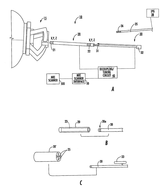
with reference to the figures. Figure 1A illustrates a MRI guided
interventional
placement system 10 that includes a mount 15, a targeting cannula 20, and an
elongate
probe 30. Although shown as a frameless mount 15, frame-based or other
suitable
mounting systems may also be used that allow for the adjustability (typically
at least
two degrees of freedom, including rotational and translational) and
calibration/fixation of the trajectory of the targeting cannula 20 and/or
probe or tool
30. The mount 15 or components thereof (and/or the patient) may include
fiducial
markers that can be detected in an MRI to facilitate registration of position
in an
image.
The system 10 may also include a decoupling/tuning circuit 40 that allows the
system to cooperate with an MRI scanner 60. An intermediate MRI scanner
interface
50 may be used to allow communication with the scanner 60. The interface 50
may
be hardware, software or a combination of same.
CA 02623616 2008-03-25
WO 2007/064739 PCT/US2006/045752
The elongate probe 30 can include at least one electrode 31 on a distal tip
portion thereof. The electrode 31 can be a recording and/or stimulating
electrode.
The electrode 31 can be configured to deliver test voltages for physiologic
confirmation of location/efficacy that can be done by fMRI or by feedback from
a
non-anesthetized patient. Thus, a patient can be stimulated with the
interventional
probe 30 (the stimulation may be via a transducer on a distal tip portion of
the probe),
to help confirm that the interventional probe is in the correct location (i.
e., confirm
proper location via anatomical as well as provide physiologic information and
feedback). During (and typically substantially immediately after) stimulation
from
the interventional probe, the physician can monitor for a physiologic response
from
the patient that can be observed either directly from the patient as a
physical response
or via an fMRI-visible response.
The elongate probe 30 can be MRI-visible and may optionally be configured
to defme an MRI antenna. The system 10 can be configured to allow for real-
time
tracking under MRI, with an SNR imaging improvement in a diameter of at least
5-10
mm proximate the probe 30 or cannula 20.
The targeting cannula 20 can also or alternately be MRI-visible. The cannula
can include an axially extending open lumen 25 that slidably receives the
probe 30.
In some particular embodiments, the cannula 20 may optionally comprise a
plurality
20 of spaced apart microcoils 21, 22 configured to provide data used to
provide 3-D
dimensional data in MRI 3-D space, such as a trajectory, or 3-D spatial
coordinates of
position of the cannula 20. As shown, the microcoils 21, 22 can each provide
data
that can be correlated to a three-dimensional (X,Y, Z) position in 3-D space
in the
body. The mircocoils 21, 22 can be in communication with the MRI scanner, and
tracking sequences can be generated and data from one or more of the MRI
scanner
channels can be used to define positional 3-D positional data and a trajectory
thereof.
In some particular embodiments, the progress of the cannula 20 and/or
interventional
probe 30 may optionally be tracked in substantially real-time as it advances
to the
target via the coils 21, 22 (similar ones of which may also or alternatively
be on or in
probe 30) and/or antenna 30a. However, real-time trac:king may not be desired
in
some embodiments.
As shown in Figure 1B, the eannula 20 can include at least one axially
extending fluid-filled hollow lumen or closed channel 23 with fluid that can
generate
MRI signal that can be detected by the MRI scanner arnd/or by an internal MRI
16
CA 02623616 2008-03-25
WO 2007/064739 PCT/US2006/045752
anienna incerperaLea on anwur IIILO che cannula 20 that can increase the SNR
of the
fluid to increase its visibility in an MRI. The fluid may be an aqueous
solution (able
to resonate at the proton frequency). The cannula 20 can include an axially
extending,
relatively thin segment, which creates a high contrast MRI image (a segment
filled
with water or other suitable contrast solution filled section/lumen). The
thickness of
the segment may be between about 0.25-4 mm (and the segment can have a tubular
shape with a diameter or may define another cross-sectional shape such as a
square
section). The cannula 20 may include MRI imaging coils (MR antenna 30a) to
increase the signal from the high contrast fluid. The targeting cannula 20 may
fit in
the mount directly or in a multilumen insert (as will be discussed further
below).
Figure 1C illustrates that the targeting cannula 20 can include a plurality of
lumens 25. At least some of the lumens 25 can be parallel with others and
extend
axially along and through the cannula 20. These lumens 25 can define parallel
tracts
to a target in vivo site that can be selectively used to advance an
interventional or
localization probe, such as probe 30. The probe 30 can be configured to be
selectively
input into one lumen 25, typically over a distance that is proximate a pivot
point or
zone over a burr hole or other patient access entry location, or serially
input into some
or all of the lumens 25, thereby providing a corresponding change of
trajectory of the
access path to the target site. Some of the lumens 25 may be MRI-active such
as
being fluid filled or configured to slidably and releasably receive a fluid
filled tube.
Some of the lumens 25 may not extend the entire length of the cannula 20.
Figure 1C
also illustrates that the probe 30 can include one or more axially extending
side arms
33 that can be sized and configured to reside, at least partially, in a
respective lumen
to provide MRI signal and appear in an MRI image. The fluid filled lumens 25
can
25 define trajectories in MRI 3D space that extend into the body. The cannula
20
(and/or multi-lumen insert 300, Figure 12A) can include fiducial orientation
markers
that indicate which side lumen is associated with which trajectory in an
image. The
fiducial marker can be defined by shapes, sizes or MRI visible signature
shapes or
features.
Figures 2A-2D illustrate that, in some embodiments, the probe 30 can include
an external sheath or sleeve 34 that can be configured to snugly reside about
the probe
30 but remain in the body as the probe is slidably removed. The sheath 34 can
include a lubricious coating or material or be otherwise configured with a
suitable
reduced coefficient of friction to allow a snug but slidable fit between the
components
17
CA 02623616 2008-03-25
WO 2007/064739 PCT/US2006/045752
30, 34. The sheath or sleeve 34 can be a relatively thin biocompatible
elastomeric
tubular body with sufficient structural rigidity to maintain the defined
delivery path to
the local tissue after removal of the probe 30. That is, when the probe 30 is
removed,
the sheath 34 does not collapse on itself and does not move from the position
as
another lead is directed down the sheath to the defined therapeutic location.
The
sheath 34 can be slidably advanced over the electrode 31 before the probe 30
is
retracted and removed from at least a distal end portion of the sheath 34 and
from the
targeting cannula 20. As shown in Figure 2C, the sheath 34 and/or probe 30 can
include externally visible indicia 34i, 30i, of axial extension that can be
visually
aligned so that a clinician can readily identify the correct movement
extension for the
sheath to be extended to be substantially precisely placed at the desired
location
identified by the electrode 31. The sheath 34 may also optionally include a
collar or
other member that can inhibit over-extension and/or bias the sheath to
translate to the
desired extension length (not shown). The sheath 34 typically extends up above
and
out of the frameless mount 15 to allow a clinician ease of access to retrieve
(pull) the
sheath 34 after the therapy and/or lead placement is complete.
In some embodiments, as shown in Figure 2E, the delivery sheath 34
described above as enclosing and housing the multipurpose probe 30 may also be
used first as a targeting cannula 20". In this embodiment, the delivery sheath
34 can
be MRI-active and include on-board MRI coils or an MRI antenna 30a that is
built-in
and during the targeting /alignment steps, a contrast filled tube 134 can be
advanced
in the delivery sheath 34 (before the multi-purpose probe 30). Once the
localization
and/or alignment steps are completed, the fluid filled tube can be replaced by
the
multipurpose probe 30 and the active delivery sheath 34 and the multipurpose
probe
30 can be advanced in the tissue. The fluid filled tube 134 may be deflated
before
removal to facilitate easy of removal.
As also shown in Figure 1A, the system 10 may optionally be used with
and/or also include at least one deep brain stimulation lead 35 with at least
one
electrode 36, typically a plurality of electrodes as shown. The lead 35 can be
delivered via the cannula 20 after the trajectory and location target are
defined using
the probe 30 and cannula 20. The electrodes 31 and 36 are shown in Figure 1A
as
generally cylindrical, but other configurations of electrodes may be used. The
terms
"lead" and "probe" can be used interchangeably to indicate a body used to
support an
interventional component such as, for example, the respective electrodes 31,
36.
18
CA 02623616 2008-03-25
WO 2007/064739 PCT/US2006/045752
Other numbers of electrodes as well as other electrode configurations can be
used.
For example, the electrodes may be translatable with respect to the probe body
or may
be statically configured thereon. It is contemplated that the electrodes can
be sized
and configured to "fit" the desired internal target, which may be a relatively
small
region, such as less than about 1-3 mm. Typically, as shown in Figure 1A, the
electrodes can be held on a distal portion of the probe body. A connector 32
on the
proximal end portion of the probe body 30 can be configured to reside outside
of the
body during lead placement. The proximal portion of the probe body can be -
configured to releasably connect with a circuit 40 and/or an MRI scanner
interface 50
via connector 32.
As shown by the broken line, the system 10 may optionally also include at
least one implantable pulse generator 38 that can connect to the implantable
lead 35.
The IPG 38 and lead 35 can also comprise MRI compatible materials and/or
components. The frameless mount 15, the targeting cannula 20, and the probe 30
may
be provided as single-use disposable sterilized components in a medical kit or
may be
re-sterilized by a clinic between uses.
The probe 30 is typically an elongate flexible probe comprising an outer layer
of elastomeric material, such as a polymer, that extends across the outer
surface of the
probe body while leaving the electrode(s) 31 configured to contact the tissue
in
position in the body. The probe 30 includes at least one conductor lead that
electrically connects the electrode 31 to a remote input or output source,
such as the
MRI scanner interface 50. The lead(s) can comprise any suitable material, and
may,
in some embodiments, comprise a shape memory alloy such as Nitinol.
The targeting cannula 20 can be an MRI-compatible, generally rigid cannula
and/or a cannula 20 with increased rigidity relative to the probe 30, and can
be
configured to slidably receive at least the distal and intermediate portions
of the probe
body 30 to guide the distal end portion of the probe 30 into the intrabody
target
position. The cannula 20 can be configured according to a desired body entry
location; e.g., for oral entry, the cannula 20 can be formed into a bite
block, nasal
cavity or ear plug member, and for non-neural uses, such as placement in the
spinal
column, no cannula may be required.
In some embodiments, the targeting cannula 20 and the interventional probe
30 can be configured as a unitary tool. In some embodiments, it is also
possible that
19
CA 02623616 2008-03-25
WO 2007/064739 PCT/US2006/045752
the targeting cannula 20 and the frameless mount 15 (with or without the probe
30)
can be a unitary tool such that the components are affixed together.
As for other components noted above, in some embodiments, the implantable
pulse generator 38 as well as the implantable lead 35 may also comprise MRI
compatible materials to allow placement of the subject using the targeting
cannula 20.
In some embodiments, as shown for example in Figure lB, the probe 30
comprises an MRI antenna 30a that is configured to pick-up MRI signals in
local
tissue during an MRI procedure. The MRI antenna 30a can be-configured to
reside on ----
the distal portion of the probe 30. The MRI antenna 30a may also optionally be
defined by the head mount 15, the targeting cannula 20 and/or by cooperating
components of one or more of the head mount 15, cannula 20 and/or the probe
30.
The MRI coils built on any of the targeting cannulas 20 herein, or on the
mount 15,
probes 30, sheath 34, multilumen insert 300, alone or in combination, can
include one
or more imaging coils of the following types: loop, solenoid, loopless, dipole
antennas, saddle, and birdcage coils. These can be actively tuned and
decoupled,
inductively coupled, etc.
In some embodiments, the antenna 30a has a focal length or signal-receiving
length of between about 1-5 cm, and typically is configured to have a viewing
length
to receive MRI signals from local tissue of between about 1-2.5 cm. The MRI
antenna 30a can be formed as comprising a coaxial and/or triaxial antenna.
However,
other antenna configurations can be used, such as, for example, a whip
antenna, a coil
antenna, a loopless antenna, and/or a looped antenna. See, e.g., U.S. Patent
Nos.
5,699,801; 5,928,145; 6,263,229; 6,606,513; 6,628,980; 6,284,971; 6,675,033;
and
6,701,176, the contents of which are hereby incorporated by reference as if
recited in
full herein. See also U.S. Patent Application Publication Nos. US
2003/0050557; US
2004/0046557; and 2003/0028095, the contents of which are also hereby
incorporated
by reference as if recited in full herein.
As noted above, the probe 30 can include at least one electrode 31 that can
operate as a sensing electrode (i.e., for micro-electric recording). The at
least one
electrode 31 can be more than one electrode and/or the electrode 31 may be
able to
both sense and stimulate. For neural uses, different regions in the brain
provide
different sensed intensities, frequencies and/or pitches (typically readings
of between
about 1-4 microvolts) which are identifiable and can allow a clinician or
software
CA 02623616 2008-03-25
WO 2007/064739 PCT/US2006/045752
additional data to confirm that the probe 30 and/or lead 35 reaches a proper
target
location.
As will be discussed further below, the mount 15 can be in communication
with a drive system that can move the mount in desired directions, such as
rotate,
adjust pitch or translation, and may advance and/or retract the cannula 20
and/or
probe 30.
Figures 3A and 3B illustrates that, in some embodiments, the core of the
-probe 30 can-be configured to hold at least one (shown as a plurality of)
axially
extending conductor(s) 26, typically a respective one for each electrode 31.
In other
embodiments, greater or fewer numbers of conductors than electrodes 31 may be
used. As noted above, the probe 30 can be a multi-purpose probe. The
conductors 26
may be static and held generally encapsulated in a first insulating dielectric
layer 61.
In other embodiments, the conductors 26 may be held in the first dielectric
material
61 so that they can translate in the axial and/or generally outward or
transverse
directions. Referring again to Figure 3B, an axially extending first shielding
layer 62
can surround the first dielectric layer 61. A second axially extending
insulating
dielectric layer 63 can surround the first shielding layer 62. A second
axially
extending shielding layer 64 can be electrically connected to the first shield
layer 62
(that may also be called a primary shield layer) at a proximal end portion
thereof. An
outer polymeric insulator layer 65 can surround the inner layers 61-64 while
terminating to typically expose the electrodes 31 to allow stronger
stimulation contact
during operation. The conductors 26 extend from the connector 30 to the
respective
electrode 31. The probe 20 includes an electrical ground 68 and the connector
30
connects the ground 68 and each electrode 31. As shown, the connector 30 can
include connector prongs (shown as two, but additional prongs may be used),
each
having a connection for a respective conductor 26 that merges into a
respective
electrode 31. Where combinations of electrodes 31 are used, the conductor 26
can
connect to two or more electrodes 31 and share a common connector 30e.
As discussed above, the probe 30 can be configured with an imaging coil 30a
to collect MRI signal data for MRI imaging/data collection capability and
include at
least one discrete electrode 31, which can be a directional electrode =
(directional/volumetric specific electrode) to be able to controllably
generate different
stimulation field patterns in different directions in situ. Directional
electrodes may
allow a more precise stimulation therapy that can be adjusted based on a
patient's
21
CA 02623616 2008-03-25
WO 2007/064739 PCT/US2006/045752
particular neural circuitry and/or physiology. For additional description of
probes
and/or components thereof, see, e.g., PCT/US/2005/026508, the contents of
which are
hereby incorporated by reference as if recited in full herein.
For example, once the stimulation lead 35 is inserted to a target neural
region
in the brain, the stimulation lead can be activated to use at least one
electrode 36,
which provides the desired therapeutic response while minimizing undesired
responses. It is contemplated that a more precise stimulation of neural tissue
that is
directionally specific can stimulate only desired neural circuitry and/or-
tissue. The
stimulation may be output to stimulate target cellular or subcellular matter.
In some
embodiments, the stimulation can generally be transmitted within about a small
stimulation volume. The probe 30 with an MRI antenna 30a can help position the
probe to between about 0.5 mm to about 1.5 mm of a target neural space, and in
other
embodiments, between about 0.1-0.5 mm. Once in the target neural space, the
stimulation electrode 31 and/or stimulation lead electrode 36 can generate a
locationally precise, controlled directional volumetric stimulation that may
allow an
increase in therapeutic efficacy for different disorders, diseases or
impairments.
Figure 3C illustrates an electrical schematic of the probe 30 shown in Figures
3A and 3B. As shown, the primary or first shield layer 62 axially terminates
at a
distal portion of the probe in advance of the first electrode 31. Although
shown with
a plurality of electrodes 31, a single electrode or fewer or greater numbers
may be
used. The primary shielding 62 may be formed into a coil 62c at a distal
portion of
the probe 30. In other embodiments, the primary shielding 62 can terminate
without
coiling (not shown). In yet other embodiments, the shielding 62 may be coiled
a
distance past one or more electrodes 31, including all the way forward to the
distal
end portion (not shown). In some embodiments, a respective conductor 26 can
extend
to a corresponding electrode 31, with the longest conductor 26 corresponding
to the
more distal electrode 31. The conductor(s).26 may be substantially linear
along the
length in the probe body as shown, or may be coiled. If coiled, the coil for
the
conductor 26 may be at a distal portion, just before the respective electrode
31, which
may increase signal (not shown). Each electrode 31 is typically in
communication
with at least one of the insulated conductors 26. At the proximal end of the
probe 20,
the conductors 26 are connected to a connector 30 so as to be connected to the
implantable signal generator 50 or to the interface circuit 40 during MRI
guided
probe/lead/cable placement. These insulated conductors 26 are typically
covered with
22
CA 02623616 2008-03-25
WO 2007/064739 PCT/US2006/045752
a polymeric insulator sleeve 61, and a conducting material is cylindrically
layered to
form the first shielding layer 62 over the insulator. This shielding 62 is
terminated
proximal to the electrodes and is not in electrical contact with the
conductors or the
electrodes. A second insulator/polymeric/dielectric layer 63 further insulates
this
shielding to form a multi-core coaxial type cable system with an impedance
that is
typically between about 10-1000 ohms. The RF chokes 64rf can be integrated or
built
into the shielding 64 in the form of a second shielding, which is not
continuous and
has multiple sections each X/4 or less in length:
As shown in Figure 3C, at the proximal end, each section or segment 64s is
connected to the primary shielding 62, and the distal end may not be
electrically
connected to the primary shielding 62, or may be connected with a capacitance
164 in
between the primary and secondary shielding, 62, 64, respectively. A top
insulator/polymeric layer 65 can be used to insulate the probe body 30b,
except for
the electrodes 31.
As shown by the axial arrow in Figure 3C, the antenna 30a can include an
MRI active portion 135 that may extend between a location where the primary
shield
62 terminates and the first electrode 311. However, as noted above, other
antenna
configurations may also be used. As shown, the second shield layer 64
comprises a
plurality of axially spaced apart RF chokes 64rf. The term "RF chokes" refers
to an
electrical configuration formed in a shielding layer and/or internal electrode
lead
configuration that provides an electrical disconnect and/or an electrical
length of less
than or equal to X/4 (from the perspective of external electromagnetic waves)
to
inhibit the formation and/or propagation of RF-induced current or standing
waves in
an AC (alternating current, e.g., diathermy applications) or RF exposure
environment.
The physical length that provides the electrical wavelength may vary depending
on
the materials used in fabricating the probe (such as dielectric constant) and
the
magnetic field in which it is used. In some embodiments, the probe 30 has a
physical
length that is greater than 10 cm, typically between about 20 cm to about 150
=cm. In
some embodiments, the implantable lead segment 35 can also include RF chokes
64rf
formed along target regions or along substantially the entire implantable
length. In
the embodiment shown in Figure 3C, the RF chokes 64rf comprise a plurality of
disconnects of the shield 64 and/or discrete electrically isolated second
shield
segments. In other embodiments, the RF chokes 64rf can include a, series of
axially
spaced apart Balun circuits or other suitable circuit configurations. See,
e.g., U.S.
23
CA 02623616 2008-03-25
WO 2007/064739 PCT/US2006/045752
Patent No. 0,284,911, and co-pendmg U.S. Patent Application Publication, US-
2006-
0252314-Al, the contents of which are hereby incorporated by reference as if
recited
in full herein, for additional description of electrical leads.
As shown in Figure 3C, the second shield layer 64 may be coupled to the first
shielding layer 62 at opposing ends of the segments 64s. As shown, one end
(typically the proximal end portion) of the disconnected segment 64s is
directly
coupled to the shielding layer 62 and the other end (typically the distal end
portion) is
capacitively coupled to the first shielding layer 62. Each segment 64s may be
configured to engage the first shield layer 62 in the same manner or in an
opposing
different electrical manner (not shown).
Figures 4A and 4B illustrate additional exemplary electrical safety circuits
that can be used in combination with other RF safety features described herein
or
alone, for probes 30 or other leads or components that may be exposed to MR
systems. Thus, although described as used with respect to probe 30, the
circuit and
conductor configurations may be used with other components or devices
associated
with embodiments of the invention.
As shown in Figure 4A, a conductive lead 30c can include a plurality of high
impedance segments 1300 that can be positioned along the length of the lead
system
30 at regular or irregular intervals, but typically so that the spacing
provides an
electrical length of less than about X/4 therebetween. The RF traps 1300 are
placed
less than about X/4 apart, where X is the wavelength in the medium of the
operating
frequency, to electrically break the long conductor into multiple sections.
The probe 30 or other member can include multiple high impedance sections
or segments 1300 along the length thereof. The high impedance sections or
segments
can be created by arranging the components of the medical device, i.e., the
conductor,
etc. as an RF trap. These high impedance RF traps inhibit the flow of induced
RF
current (at the frequency to which the RF trap is tuned) and prevent it from
heating
tissue adjacent to the electrodes, thus minimizing or preventing RF induced
tissue
damage. Since the physiological and stimulation signals are at low frequencies
(KHz
range), the RF trap allows the lower frequency signal(s) to go through,
trapping only
the higher frequencies of interest to which the traps are tuned.
As shown in Figure 4A, the conductor 30c can be in electrical communication
with the shield at the distal portion of the high impedance segment 1300 via a
tuning
capacitor 1340. The high impedance segment 1300 (e.g., RF trap) can be tuned
to a
24
CA 02623616 2008-03-25
WO 2007/064739 PCT/US2006/045752
MRI frequency. The segment 1300 can also be configured so that the conductor
30c
at the proximal end portion of the segment 1300p is connected to the shield
1325 via a
capacitor 1360. One or more of the different high impedance segments 1300
(shown
as 13001, 13002, 13003) may be tuned to different MRI frequencies (i.e., 64
MHz and
128 MHz or other standard operating frequencies of commercial MRI scanners).
The
impedance of the segment 1300 can be at least 400 Ohms, typically greater than
about
450 Ohms. The at least one high impedance segment 1300 can be placed at
between
about 0.1-12 cm from the electrode(s) 31. The lead 30c can be configured with
a
straight segment 1311 that merges into the coiled segment 1310.
In operation, the RF trap(s) 1300 with the shield 1325, inductor 1310 and
tuning capacitor 1340 form a high impedance parallel resonant circuit at the
desired
frequency to block RF currents along the conductor. The tuning capacitor can
include one or more of a discrete capacitor 1340 and/or stray capacitance
between the
inductor 1310 and the shield 1325.
Figure 4B illustrates that a plurality of conductors (shown as three) 30c1,
30c2,
30c3 can be co-wound (see element 1310c) and reside within a common flexible
shield 1325. Each conductor 30c1, 30c2, 30c3 can be electrically connected to
the
shield 1325 at a proximal portion thereof, directly or indirectly, such as
using a
respective capacitor 1360 as shown. The capacitor 1360 can provide an RF
short.
The high impedance segments 1300 (RF traps) are placed less than a aJ4 apart
from
each other at the desired frequency. The coiled segments of the conductors can
define
inductors and can each connect a different distal electrode.
When multiple high impedance segments 1300 (using, for example RF traps)
are incorporated over the length of a device such that the distance between
two
adjacent traps is less than one-quarter wavelength, this effectively breaks
the long
conductor into multiple sections, each shorter than a quarter wavelength. The
RF
current induced on a conductor is a function of length of the conductor at the
RF
frequency, and when the conductor is shorter than a quarter wavelength, the RF
current induced is not large enough and may not cause undue RF deposition RF
induced-treating of the tissue.
In some embodiments, as shown for example in Figure 2D, the probe 30 can
be configured with one or more lumens 39 and exit ports that deliver desired
cellular,
biological, and/or drug therapeutics to the target area, such as the brain.
The probe 30
CA 02623616 2008-03-25
WO 2007/064739 PCT/US2006/045752
may also cooperate with and/or incorporate biopsy and/or injection needles
and/or
ablation means.
Embodiments of the present invention can provide a multi-function MRI safe
lead or probe 30 that can operate at least bimodally: namely, during MRI
procedures
to obtain MRI signal from local tissue in vivo and to stimulate the target
tissue during
an MRI procedure. The system 10 can be configured for use in any suitable MRI
scanner, such as low field magnets (typically about 0.5-1.0 T fields), to a
conventional
1.5T magnet or-higher; such as 2T, 3T or even higher. MRI scanners are well
known
to those of skill in the art and include, but are not limited to, SIEMENS and
GE MRI
systems.
Configuring a probe 30 to function both as an MRI antenna 30a (alone or
cooperating with other components) and a stimulation and/or recording probe 31
may
reduce the time needed to place the electrodes in the desired location,
provide for
increased accuracy in location and/or reduce the number of times a device is
inserted
into the brain or other target region.
Figure 5 illustrates a circuit 100 that can provide the bimodal operation of
the
probe 20. As shown, the.circuit 100 includes a splitter circuit 102 that is in
communication with an electrode stimulation circuit 110 that provides the
stimulation
to the electrode(s) 31. The splitter circuit 102 is also in communication with
an RF
transmit decoupler circuit 115 that is in communication with an MRI antenna RF
receive circuit 120 and the antenna 30a on probe 30. Certain or all of the
components can be held in the MRI scanner interface 50. In other embodiments,
certain or all of the components of the circuit 100 can be held in the
connector 32.
Generally stated, in some embodiments, the probe 30 can have at least two
primary operational modes with different electric transmission paths, which
are
electrically directed using the splitter circuit 102. In operation, during an
MRI
procedure, an RF excitation pulse is transmitted to a subject. The MRI antenna
30a is
decoupled during RF transmission, then operative during a receive cycle to
receive
signal from local tissue. The at least one stimulation electrode 31 is
typically isolated
via the splitter circuit 102 so that only the MRI antenna portion of the probe
30 is
active. The MRI interface 50 (Figure 1) communicates with the MRI scanner and
may be configured with a supplemental port to allow the implantable pulse
generator
or another stimulation source to connect thereto, thereby allowing the IPG or
another
stimulation source to stimulate the electrodes without decoupling the
interface during
26
CA 02623616 2008-03-25
WO 2007/064739 PCT/US2006/045752
the placement procedure (confirming proper placement). In some embodiments,
the
MRI interface 50 can include a stimulation and/or sensing mode that operates
the
electrodes.
During MRI-guided clinical implantation of the probe 30, the probe 30 can
first be used as an MRI antenna to provide high resolution imaging of the
target
internal anatomy (such as neural tissue) and to locate the position of the
electrodes 31
in the body by obtaining MRI signals and, hence, images that are acquired by
the
external-coils and/or internal MRI antenna. The electrodes-31 can also be -
used to -
assess location via acquiring electrical signals from and/or stimulating the
target
(neural) anatomy.
Figure 6 illustrates a different circuit 100 that may be used to provide the
different operational modes of the probe 30. Figure 6 illustrates an MRI
antenna
receive circuit 135c that receives the MRI responsive signal from local tissue
and an
RF transmit decoupler circuit 135D that can decouple the antenna 30a and the
electrodes during RF transmission. The circuit 100 also includes an electrode
stimulation circuit 125 that provides the stimulation pulses to the
electrode(s) 31 and
can include an electrode pulse filtering circuit 225 and a recording electrode
circuit
226 used to gather local microelectric signals.
Figure 7A is a schematic illustration of an exemplary splitter circuit 102
that
provides different transmission paths for signals operating in the imaging (MR
signal)
mode and in the sensing microelectrical mode according to some embodiments of
the
present invention. Figure 7A illustrates that the circuit 102 can have two
sides,
102A, 102B, respectively that substantially overlie each other as shown in
Figure 7B
with a ground plane therebetween. Side A 102A includes the active path of the
MRI
antenna 30a with matching and tuning components including decoupling
capacitors
127, conductor connections 126 (to respective conductors 26), an input (shown
as a
BNC input) to the MRI scanner 131, an input to a multi-pin connector for an
electrode
pulse signal 132 (EP signal) a PIN diode 128, a matching tuning inductor 129
and a
matching/tuning circuit capacitor 130. Side B 102B is the electrode
operational
circuit configured to act as a high pass filter. As shown, the respective
electrical
transmission paths to the conductors 26 include capacitors 138 (shown as 1000
pF
capacitors) and 64 MHz RF blocking inductors 139. The blocking inductors 139
can
be changed to block the frequency of the MRI system in use (higher frequencies
for
higher field magnets, i.e., for proton imaging, 96 MHz for 2T, 128 MHz for
3T). It is
27
CA 02623616 2008-03-25
WO 2007/064739 PCT/US2006/045752
noted that components of the exemplary circuits are shown with respect to side
A or B
for ease of discussion, but certain of the circuits (or the entire circuit)
may reside on a
different side than that shown (and are not required to be on one side).
In some embodiments, the probe 30 can be placed in the brain, such as in the
subthalamic nucleus or other deep brain target via a burr hole formed in the
skull.
MR imaging using the probe 30 can guide an increased accurate placement in the
thalamus or other desired anatomies. Further, the electrical signals from the
local
tissue can be analyzed and evaluated to determine a final location of the
electrodes 31
for stimulation electrodes 36 on lead 35. During this time, the probe can be
connected
to the MRI scanner interface 50 that can include a matching-tuning decoupling
circuit
40 (Figure 1A), and a splitter circuit to separate MR signal from the
electrical signals
generated by the local target tissue. Once the probe system is appropriately
located in
the desired anatomy, the stimulator can be connected for physiological
confirmation
of the function. A telescopic system to lengthen or shorten the lead may be
implemented in the proximal section of the probe, since diameter/profile may
not be a
significant concern in this region.
As noted above and shown with respect to Figure 2D, the probe 30 may have
one or more lumens 39 configured to deliver cellular and/or biological
therapeutics to
the desired neural tissue. The delivery lumens 39 may be medially located or
be
formed off-center, such as a channel in a sidewall of the device (not shown).
The
lumens 39 may be configured to receive an extendable needle that may exit the
probe
from the distal end or from the sides, proximal, distal, or even through the
electrodes
to precisely deliver cellular/biological therapeutics to the desired anatomy
target.
This delivery configuration may be a potential way to treat patients, where
the
cellular/biological therapeutics are delivered into the desired anatomy and
the
neurotransmitter/signal generator paces the cells to modify their function. In
this way,
even if the signal generator fails, the cells (stem cells) may differentiate
and take over
the function. MRI can be used to monitor the efficacy of the therapy in the
brain.
The stimulation lead 35 and probe 30 can be sized and configured to have
substantially the same cross-sectional area or one may cooperate with a sleeve
so as to
be held snugly in the sheath 34 and/or targeting cannula 20 and/or mount 15.
For
example, in some embodiments, a non-conductive elastomeric sleeve (not shown),
coating or other configuration can be used to size the stimulation lead 35
and/or
probes 30 to snugly fit the cannula 20 as desired. In other embodiments, an
insert can
28
CA 02623616 2008-03-25
WO 2007/064739 PCT/US2006/045752
be used to adjust the size of the holding port or lumen of the cannula 20 to
correspond
to that of the probe in use (also not shown). The cannula 20 and both
lead/probes 30,
35, respectively, can be MRI-compatible and may include the RF-safe circuits
such as
RF chokes, Balun circuits and/or other RF safe configurations. See, e.g., co-
pending
5' PCT patent application identified by Attorney Docket No. 9450-7W0 and U.S.
Patent
No. 6,284,971, the contents of which are hereby incorporated by reference as
if
recited in full herein.
In some embodiments, the antenna portion of the probe 30 can def ne-a --
relatively small MRI receiver length "L," such as less than about 5 cm,
typically
between about 1-2.5 cm as noted above. As before, the antenna 30a can be any
suitable type and is not limited to a coaxial cable type (including, for
example, a
dipole or loopless antenna as discussed above). The probe 30 can be configured
to
defme the antenna 30a alone or in combination with other components. For
example,
in some particular embodiments, the cannula 20 or sheath 34 can form a
shielding
layer. In some embodiments, the cannula 20 may comprise a polymer and may
include MRI compatible conductive material, such as Nitonal.
In some embodiments, one or more of the mount 15, a multi-lumen insert 300
(Figure 12A) or cannula 20 can be configured to cooperate with the probe 30 to
defme an MRI antenna 30a. The insert 300, mount 15 and/or cannula 20 can
provide
a ground and positive signal path. With reference again to Figure 3C, the
cannula 20
can provide one or more insulating layers 61, 63 or shielding layers 62, 64
with the
antenna probe 30 providing at least one conductor 26 and potentially one or
more of
the insulating layer 61 or shielding layers 62, 64. In particular embodiments,
the
cannula 20 provides the secondary shield layer 64 and may include RF chokes
64rf.
As will be discussed further below, the system 10 can include circuits and/or
modules that can comprise computer program code used to automatically or semi-
automatically carry out operations to stimulate, sense signals in vivo, and/or
determine
a probe location, a scan plane and localization trajectory(ies) and the like.
The
module can be in communication with the probe 30.
The system 10 can be configured to electronically obtain and monitor patient
response data can include electrophysiological input from sensors held on the
body,
such as, but not limited to, heart rate, blood pressure, movement sensors to
detect an
increase or decrease in patient movement (to detect shaking or tremors in
limbs and
the like), fMRI data, local cellular audio and/or electrical activity (such as
using a
29
CA 02623616 2008-03-25
WO 2007/064739 PCT/US2006/045752
sensing electrode), or other patient response data. Supplemental external or
internal
sensing electrodes may also be positioned on/in the patient and automatically
input to
a module to assess whether detrimental responses or inadvertent activation of
non-
target neural circuitry may be stimulated. The module may also be configured
to
accept input of patient response data (that may be input by a clinician using
a
computer entry screen) to input when detrimental or advantageous responses are
indicated. The patient response data can be input as an input variable for
correlation
analysis with other input variables. Where used,-the clinician may enter data
using a-
remote or local computer, a portable communications device, or other wireless
or
wired device. However, in some embodiments, it may be desired to carry out the
evaluation in a substantially automated manner, allowing for a potentially
faster
stimulation evaluation protocol and patient-specific stimulation
determination.
In some embodiments, as shown in Figure 8, the system 10 can include an
automated Localization Control Circuit lOc that communicates with an MRI
scanner
500 and, optionally, the adjustable mount 15 that resides in the magnetic
field B. of
the MRI scanner. The Circuit 10c can direct the MRI scanner 500 to run certain
imaging sequences to identify the scan plane that an elongate member resides
in, in
3D MRI space, held in the mount 15. The system 10 may interface with the MRI
scanner and provide input to drive the scanner 500 to the desired imaging
planes, as
they are prescribed on the system (circuit and/or software) as opposed to the
scanner
500. Alternatively, the system 10 (circuit and/or software) can provide
information to
an operator that allows the scanner operator to select and initiate the
imaging planes
identified by the system 10.
The Circuit 10c can include a signal processor configured to analyze pixel or
voxel data to define the scan plane automatically and relatively quickly from
image
data that renders the elongate member with higher intensity (greater SNR) in a
target
region of a patient. The system can cooperate with an MRI scanner to identify
the
scan plane in which an elongate targeting marker, such as a sheath 34, insert
300,
targeting cannula 20 and/or probe 30 reside. That is, the elongate member is
MRI-
visible and configured to have increased SNR relative to other features in the
image
such that data review of pixels or voxels can define the location of the
member and
identify the scan plane associated therewith.
CA 02623616 2008-03-25
WO 2007/064739 PCT/US2006/045752
The Circuit lOc can determine what adjustments are suitable to move the
mount 15 to a desired configuration so as to defme the targeting or desired
access path
trajectory to intersect with target tissue.
Figure 9 is a block diagram of some operations that may be carried out
according to embodiments of the invention. As shown, a scan plane associated
with
the elongate targeting cannula and/or probe (or other MRI visible elongate
member)
residing in 3D MRI space and having a first trajectory can be
programmatically,
typically automatically, determined (block 600), whereby the- cannula or probe
acts as
an MRI detectable marker. That is, the system 10 can be configured to identify
and
provide 3D coordinates of one or more of the elongate member, the target, the
burr
hole location, etc. in the MRI space. This data can direct which imaging plane
to use
to observe the probe and/or access path trajectory or direct the operator to
prescribe
the imaging plane on the scanner.
In some embodiments, the scan plane can be determined by electronically
(programmatically) reviewing MRI data (typically from at least two images
taken at
oblique angle images) to determine'high signal intensity data associated with
the
targeting cannula and/or probe (or sheath or other elongate member) (block
605). The
signal intensity data may be of pixels or voxels. In some embodiments, the
methods
may also or alternatively include electronically (programmatically) reviewing
3D
volumetric scan data for high signal intensity data to determine the location
of the
target elongate component, i.e., targeting cannula and/or probe in 3D MRI
space
(block 610).
In some embodiments, after the scan plane is determined, positional
adjustments (e.g., degrees of rotation, or translation) of the mount holding
the cannula
and/or probe (or other member) can be electronically determined to generate a
second
adjusted trajectory to the target site (block 620). The adjustments can be
output to a
user to allow the user to physically manually change the mount settings using
visual
indexing or electronic inputs (touch screen or other input means) to allow a
user to
alter the mount configuration (block 621). Alternatively, the system can be
fully
automated so that the new adjustments can be automatically applied via an
automated
drive system. That is, a position of an RCM associated with a head mount can
be
electronically determined (i.e., registered in an image) (block 622). A
calibrated
"current" or "start" position of the head mount can be electronically
determined and
registered to a first trajectory in 3D MRI space using transducers, optical
encoders
31
CA 02623616 2008-03-25
WO 2007/064739 PCT/US2006/045752
and the like. A change in one or more of rotation, tilt or translation of the
mount can
be programmatically calculated to achieve the desired adjusted trajectory
(block 624).
T'he system 10 can also include an automated MRI scan plane and trajectory
determination module that can define position adjustment data for the mount 15
(e.g.,
head mount or other mount type). The adjustment data can be output to a
clinician to
define the frame adjustment inputs (i.e., coordinates) to adjust the
trajectory of the
frame to the desired intersection with target tissue. In other embodiments,
the
adjustment data can be used to automatically adjust the frame position on the
patient
using automated position or adjustment drive systems to obtain an adjusted
trajectory
without requiring manual input.
In some embodiments, the system 10 can include a Graphic User Interface
(GUI) that allows a clinician to define a desired trajectory and/or end
position on a
displayed image, then can electronically convert the orientation/site input
data
programmatically to generate the frame position data (not shown). The GUI can
include an interactive tool that allows a clinician to draw, trace or
otherwise select
and/or identify the target treatment site and/or access path trajectory. The
system 10
can then be configured to identify the lumen of choice and/or adjustments to
the
mount 15 that is most likely to achieve this trajectory.
In some embodiments, the system 10 includes a user interface that can be
configured to carry out one or more of the following: (a) electronically
determine the
location of the targeting cannula/frameless headmount and a trajectory
associated
therewith; (b) based on the determined location of the frameless headmount,
determine adjustments to the headmount so that the desired trajectory is
achieved, and
provide the adjustment/setting information to an operator (or automatically
adjust the
settings for automated systems with feedback control); and (c) display MRI
images
with the projected trajectory and intersection point(s) on that will be
followed if the
interventional/surgical device/lead is advanced using a defined position of
the
headmount.
In some embodiments, the location and orientation of one or more elongate
marker(s) (e.g., targeting cannula) in 3D MRI space may be programmatically
determined by obtaining sagittal and coronal projection images, applying high
intensity filtering, then using image recognition (such as an image
recognition mask)
and/or linear regression to find coordinates of the elongate marker (e.g.,
cannula) in
space.
32
CA 02623616 2008-03-25
WO 2007/064739 PCT/US2006/045752
Alternatively or additionally, the location and orientation of the above-
described elongate marker(s) (e.g., targeting cannula) in 3D MRI space may be
determined by obtaining a 3D volumetric scan, applying high intensity
filtering, then
using 3D image recognition (such as an image recognition mask) and/or linear
regression to find coordinates of the elongate marker (e.g., cannula) in
space.
More particularly, the location and orientation methods described above with
respect to the projection images can be carried out as described below. First,
sagittal
and coronal projection images can be taken of the-region encompassing-the
marker
(e.g., targeting cannula). Next, these image arrays are "padded" by adding
zeros to
the left, right, top, and bottom of the image arrays so that an image
recognition mask
can be effectively applied to the edges. These images are processed so that
points in
the arrays with signal intensity less than a given threshold are assigned a
value of 0,
and points above the threshold are given a value of 1. Then, an image
recognition
mask A (an a * b array) that traces out the shape of the marker (e.g.,
targeting
cannula) for a given angle is applied to the images as follows:
a. Starting at the point (0,0) in the image I (which is an m by n array)
calculate the sum of the values of I(x,y)*A(x,y) for x:[0,a], y:[0,b].
b. Repeat at points (1,0), (2,0), ..., (m-a,0) in A.
c. Repeat in rows 1, 2, ..., n-b in A.
After these steps are completed for a filtering mask at a given angle, repeat
with a mask where the cannula is to be recognized at a different angle. Repeat
the
process for suitable angles (such as all reasonably possible angles). The
point where a
mask creates the highest summation at a given angle can be recognized as the
lower
left corner of the rectangle defined by the position of the marker (e.g.,
cannula) in
space, and the angle for that sum is the angle of the marker (e.g., cannula).
As an alternative to the image mask, the sagittal and coronal image data can
be
processed so that points in the arrays with signal intensity less than a given
threshold
are assigned a value of,0, and points above the threshold are given a value of
1. Next,
a linear regression is performed on the points in the image to obtain the line
the
cannula lies on in each projection. The first and last points along this line
having a
value of 1 define the marker (e.g., cannula) in space.
With respect to the 3D scan methodology, first a 3D scan of the region
encompassing the marker (e.g., targeting cannula.) is taken and/or obtained.
Next, the
image array is "padded" by adding zeros to the left, right, top, bottom,
front, and back
33
CA 02623616 2008-03-25
WO 2007/064739 PCT/US2006/045752
of the image arrays so that an image recognition mask can be effectively
applied to
the edges. These images are processed so that points in the arrays with signal
intensity less than a given threshold are assigned a value of 0, and points
above the
threshold are given a value of 1. Next, a image recognition mask A (an a * b *
c
array) that traces out the shape of the targeting cannula for a given angle is
applied to
the images as follows:
a. Starting at the point (0,0,0) in the image I (which is an m by n by o
array) calculate the sum of the values of I(x;y,z)*A(x,y,z) for x:[O,a],
y: [o,b], z: [o,c].
b. Repeat at points (1,0,0), (2,0,0), ..., (m-a,0,0) in A.
c. Repeat in rows 1, 2, ..., n-b in A.
d. Repeat in planes 1, 2, ..., o-c in A.
After these steps are completed for a filtering mask at a given angle, repeat
with a mask where the cannula is to be recognized at a different angle. Repeat
for all
desired angles (typically for all reasonably possible angles). The point where
a mask
created the highest summation at a given angle is recognized as the lower left
front
corner of the rectangular solid defined by the position of the marker (e.g.,
cannula) in
space, and the angle for that sum is the angle of the marker (e.g., cannula).
As an alternative to the image mask for the 3D scan analysis, these images can
be processed so that points in the arrays with signal intensity less than a
given
threshold are assigned a value of 0, and points above the threshold are given
a value
of 1. Next, a linear regression is performed on the points in the image to
obtain the
line the marker (e.g., cannula) lies in. The first and last points along this
line having a
value of 1 define the marker (e.g., cannula) in space.
If the elongate marker is a targeting cannula that is used with a multi-lumen
insert that attaches to the mount 15 and/or if the targeting cannula itself
includes
multiple lumens, additional information about the path defined by each or more
than
one lumen can be projected and serially or concurrently displayed on the
display,
typically a display at a clinician imaging interface workstation.
Figure 10A illustrates an example of a frameless mount 15. As shown, the
mount 15 includes a base plate 190 with an open access lumen 192 that can be
affixed
to a patient, such as to a skull over a burr hole. The mount 15 also includes
a port
194 configured to hold the targeting cannula 20 or multi-lumen insert 300
(Figure
12A), or both (serially). As shown, the mount 15 also includes upwardly
projecting
34
CA 02623616 2008-03-25
WO 2007/064739 PCT/US2006/045752
arms 196 that hold the port 194. The port 194 can slide (translate) forward
and
rearward over a curvilinear path defined by the arms 196. The arms 196 can
translate
and rotate with respect to the base 190. In the embodiment shown, the arms 196
attach to a rotatable platform 198 that is attached to the base 190.
Figures 10B-10E illustrate exemplary user adjustment members 198r, 196t.
The rotation adjustment member 198r and the translation adjustment member 196t
can each comprise at least two members as shown in Figure 10C, to allow for
ease of
access to the members when-mounted-and the patient resides- in the bore of a
magnet -
associated with an MRI scanner (and/or accommodate either right or left handed
users). The translation adjustment member can adjust pitch (tilt or swivel)
while the
rotation adjustment member 198r allows the rotation of the receiving port 194.
In some embodiments, one or both of the adjustment members 198r, 196t can
be in communication with non-ferromagnetic flexible drive shafts or cables
198d,
196d (Figures lOB,10i)) that may extend a suitable distance (e.g., between
about 1-4
feet) to allow a clinician to adjust the settings on the mount 15 without
moving the
patient and from a position outside the bore of the magnet. In other
embodiments, the
flexible drive shafts can extend a longer distance to an automated control
module
associated with the Control Circuit 10C (Figure 8) that can automatically
adjust the
mount trajectory using the input members 198r, 196t, based on an electronic
analysis
of a target trajectory in MRI data.
In some embodiments, the location/trajectory of the mount 15 can be adjusted
manually or via a drive (manual, mechanical, electrical, piezoelectric,
pneumatic,
hydraulic, etc.) and manually or automatically and locked in the final desired
orientation. If drive cables 198d, 196d and electrical connections are used,
these may
be removable once the mount 15 is aligned in the desired position. The mount
15
may have calibrations (markings) and/or optical encoders, piezoelectric
encoders, etc.
to determine the settings of the mount and extent of adjustment carried out.
The
sensors or position encoders can provide a feedback loop that can be used if
automated features in positional adjustment are used. Also, once the (head)
mount is
locked, these encoders can provide data to a monitoring system to monitor the
locked
position and alert of any unplanned changes to the headmount settings during a
procedure.
Figure lOB illustrates that the multilumen insert 300 can be integral with,the
mount 15. As shown, the insert 300 can attach directly to the mount arms 196.
In
CA 02623616 2008-03-25
WO 2007/064739 PCT/US2006/045752
other embodiments, as shown in Figure 10E, the insert 300, if used, can be a
separate
component or releasably attached to a holding member defining the mount port
194.
Figures 11A-11F illustrate different configurations that the mount 15 can take
to define a desired access path trajectory extending from the port 194 down
and
through the RCM (pivot zone) 192p into a patient.
Where the mount 15 is configured as a head mount, the fixture is mounted to
the patient's skull, typicaily threaded or friction fit to a rigid (threaded)
burr insert or
ring over the burr hole, to provide a stable frame to advance surgical
devices, leads,
etc. in the brain. The frameless headmount 15 may be a fixture with two or
more
degrees of freedom (rotate and translate/swivel) around the RCM. This RCM may
be
between about 3 cm from the surface of the skull.
The frameless headmount 15 allows the operator to align the access path
trajectory to an internal target site, such that the interventional/surgical
device/lead,
therapy, etc. will be delivered to the target site following the desired
trajectory
thorough the cranial tissue. This trajectory goes through the RCM point.
In some embodiments, after a burr hole is drilled and the frameless headmount
is fixed to (in or on) the patient's skull, the first step is to register the
position of the
headmount, and the trajectory the interventional/surgical device/lead will
follow if
advanced through the headmount. This may be done by multiple ways. For
example,
the frameless headmount may have active or passive MRI/CT/ultrasound/optical
fiducial markers, tracking coils for MRI, which can allow the operator to
register the
position of the frameless headmount and the RCM point at any given time based
on
MRI/CT/ultrasound/optical images. The position registration can be determined
by
analyzing image data obtained in any suitable ways, such as, but not limited
to,
projection images in a plurality (2 or more) of substantially orthogonal
planes, etc., or
3D volumetric scans as described above.
As shown in Figures 12A-12E and 13A-13C, the mount 15 (frameless or
framed) may hold a multilumen insert 300, through which the cannula 20, the
probe
and the lead 35 may be advanced. Fiducial markers may optionally be
30 incorporated as appropriate on the mount 15 and/or the multilumen insert
300 to
facilitate registration of the orientation of the lumens 305 of the multilumen
insert
300. One or more of the lumens 305 may hold a fluid-filled tube (not shown) or
include a fluid-filled channel that makes the lumen MRI visible. Each or some
of the
lumens 305, alone or with elongate inserts, may be in communication or include
MRI
36
CA 02623616 2008-03-25
WO 2007/064739 PCT/US2006/045752
imaging coils (not shown). The insert 300 can include fiducial markers that
allow a
clinician to visually denote which lumen provides the desired trajectory
(particularly
relevant for the outer lumens 305p (Figure 12A) rather than the medial lumen
305c).
The fiducial markers referenced herein may be provided by tracking coils,
imaging coils or even, for devices having segments with fluid filled or MRI
contrast
material, configuring those segments or lumens with a different MRI visible
shape
and/or axial starting location (such as, for example, to be arranged as longer
to shorter
in a defined perimeter direction), or combinations -thereof.
Figure 14 illustrates a targeting cannula 20 with an open through lumen 25
that is sized and configured to allow a probe 30 (typically with an external
sheath 34,
Figure 2C) to slidably advance therethrough. This cannula 20 may reside in the
port
194 without the use of a multi-lumen insert 300 (e.g., directly or with a
fitting sleeve
or collar, and the like). As shown, the cannula 20 can also include at least
one closed
axially extending fluid-filled hollow lumen 23 that surrounds the lumen 25.
The
closed fluid lumen 23 can include at least one fluid (typically liquid) fill
port 23p that
can be used to inflate the lumen 23 before, during and/or after the lumen 23
is placed
in the cannula 20. The fluid lumen 23 can be defined by a tubular elastomeric
body
or may be defined by a channel formed in the cannula 20. The cannula 20 can
also
incude one or more grooves 27 to hold an MRI imaging coil. As also shown, the
cannula 20 can include at least one substantially spherical fluid-filled end
portion 20s1
that may reside a distance of between about 5-15 cm above the RCM point. The
cannula 20 may also include a second fluid-filled substantially spherical end
portion
20s2 typically residing proximate the RCM point. The spherical end portions
20s1,
20s2 may be a part of the lumen 23 or may be discrete and separate from the
lumen
23.
In some embodiments, the MRI coil can reside on the outside of the cannula
20, and may be a loop MRI coil. The MRI coil can enhance the MRI signal in the
fluid, thereby allowing the operator to visualize the fluid filled sections
very clearly.
If required, another fluid filled tube may be inserted in the through lumen
during the
primary registration and alignment steps. Once the alignment is done, this
tube is
removed and replaced with a multipurpose probe 30 with delivery sheath 34.
In some embodiments, the targeting cannula 20, the multipurpose probe 30
and/or delivery sheath 34 can be used to provide additional signal from the
contrast
filled fluid in the targeting cannula 20. This may be used in place of the MRI
coil
37
CA 02623616 2008-03-25
WO 2007/064739 PCT/US2006/045752
built on the outer sides of the targeting cannula shown in Figure 14. It is
also noted
that, different designs can be incorporated so that the probe lumen of the
cannula 20 is
at locations other than that at the central trajectory, i.e., it may be
parallel to the
central trajectory or at controlled angle to the central trajectory.
Figure 15A illustrates a targeting cannula 20 that is configured to reside in
a
lumen 305 of the insert 300. This targeting cannula 20 can include axially
spaced
apart, substantially spherical fluid-filled segments 20s17 20s2. In this
embodiment, the
segments may reside above the lumen 305. A fluid-filled lower leg 201 can
reside in-
the lumen 305 and extend to the RCM point 192p. The fluid can comprise an MRI
contrast-enhancing liquid that can be used to define the trajectory of the
mount 15
when residing in a lumen 305. Figure 15B illustrates that the targeting
cannula 20
can include at least one side arm 20a that can reside in a different lumen 305
of the
insert 300. The side arm 20a can also include a fluid filled channel and may
optionally include axially spaced apart substantially spherical segments. The
targeting cannula (contrast medium filled) side arm 20a can provide data that
can
allow identification of a recise orientation of the multilumen insert 300.
In the embodiments shown in Figures 15A and 15B, the fluid/contrast filled
segments may be relatively thin, such as between about 0.5 mm to about 4 rnm,
typically between about 1 mm to about 3 mm. The segments can delineate the
trajectory the interventional device 35 and multipurpose probe 30 (with
delivery
sheath 34) will take with the alignment of the head mount 15. The contrast-
filled
spherical sections and the straight thin contrast-filled sections of the
targeting cannula
may provide the imaging signature that can be used for finding the location of
the
targeting cannula in the 3D MRI space and provide visual confirmation of the
trajectory of the device in the tissue. The targeting cannula 20 can have one
or more
MRI coils (loop, loopless, solenoid, etc. incorporated in the design). Also,
tracking
coils can be optionally incorporated at various sections of the targeting
cannula to
provide 3D location information in MRI space.
Figures 16A and 16B illustrate that, where a multi-lumen insert 300 is used,
images can be displayed with lines that indicate the trajectory 300t1-300t4
(where four
lumens are used) followed by each lumen 305 of the multilumen insert from the
lumen 305 to the target site 1000t. Figure 16A corresponds to projections in
an
oblique coronal/sagittal image while Figure 16B illustrates the corresponding
end
points of the lines in an axial/oblique scan. The targeting cannula 20 may be
modified
38
CA 02623616 2008-03-25
WO 2007/064739 PCT/US2006/045752
as shown in Figure 15 and/or fiducial markers may be incorporated on the multi-
lumen insert 300 and/or mount 15.
Figures 17A-17C illustrate steps associated with a typical surgical procedure.
1- Place the patient in an MR scanner and obtain MR images of the patient's
head
1000 that visualize the patient's skull, brain, fiducial markers 1005 and ROI
(region of
interest or target therapeutic site). The MR images can include volumetric
high-
resolution images of the brain.
2- To identify the target ROI, certain known anatomical landmarks can be used-
, i.e.,
reference to the AC, PC and MCP points (brain atlases give the location of
different
anatomies in the brain with respect to these point) and other anatomical
landmarks.
3 - The location of the burr hole may optionally be determined manually by
placing
fiducial markers on the surface of the head or programmatically by projecting
the
location in an image.
4- Image in the planned plane of trajectory 1010 and confirm that the
trajectory is
viable, i.e., that no complications with anatomically sensitive areas should
occur.
5 - Optically or manually mark one or more desired locations to drill the burr
hole.
6- Drill the burr or patient access hole.
7- Fix the burr hole ring (where used).
As shown in Figures 18A-18E, the following sequence can then be carried
out.
8 - Fix the Frameless or frame based head mount.
9- Fit the targeting cannula.
10 - Obtain localization scan to determine/register the location of the
targeting
cannula, in direct orientation of the headmount.
11 - Electronically derive the settings to which the headmount should be
adjusted so
that the targeting cannula is in the desired trajectory plane.
12 - Confirm this by imaging in one or more planes orthogonal to the desired
trajectory plane.
13A - If the targeting cannula is so configured (as shown in Figures 18D and
18E)
advance the multipurpose probe and delivery sheath through the targeting
cannula.
13B - If the targeting cannula will not allow that; remove the targeting
cannula and
use the central lumen of the multi-lumen insert - advance the multipurpose
probe and
delivery sheath in the central lumen of the multilumen insert. Also, the
targeting
cannula can be configured to fit in the central lumen of the multilumen
insert.
39
CA 02623616 2008-03-25
WO 2007/064739 PCT/US2006/045752
14 - Advance the multipurpose probe and delivery sheath, when imaging in the
trajectory plane, monitoring that the multipurpose probe is in that imaging
plane and it
will reach the target accurately.
15 - On positioning the multipurpose probe in the target site, obtain high-
resolution
images of the anatomy, deliver a stimulation pulse, and optionally measure EEG
signal with the multipurpose probe.
16 - If multipurpose probe and delivery sheath are at the desired target,
leave the
sheath in place and remove the multipurpose probe; this sheath will now act as
the
delivery cannula for the implantable lead.
17 - If the multipurpose probe and delivery sheath are not at the
desired/optimal
location, decide where the multipurpose probe and delivery sheath need to be.
Adjust
the headmount accordingly or use another appropriate lumen of the multi-lumen
insert
and readvance the multipurpose probe and delivery sheath.
18 - Once the multipurpose probe and delivery sheath are at the desired
location,
remove the multipurpose probe and leave the delivery sheath in place.
19 - Advance the lead to the target location using the sheath as a guide.
- Confirm the location of the lead by reviewing an image, acoustic recording
and/or stimulation.
21 - Remove the sheath, leaving the lead in place.
20 It is contemplated that embodiments of the invention can provide an
integrated
system that may allow the physician to place the interventional device/leads
accurately and in short duration of time. In some embodiments, once the burr
hole is
drilled, and the frameless head mount is fixed to the skull; the head mount is
oriented
such that the interventional device advanced using the frameless headmount
follows
the desired trajectory and reaches the target as planned in preoperative setup
imaging
plans. As described herein, the system 10 can employ hardware and software
components to facilitate an automated or semiautomated operation to carry out
this
objective.
In some embodiments, the system 10 can include one or more software
modules that can automate or carry out aspects of the invention, as shown for
example, in Figures 19 and 20.
The modules can include data processing systems and computer program
products in accordance with embodiments of the present invention. The data
processing systems may be incorporated in a digital signal processor in any
suitable
CA 02623616 2008-03-25
WO 2007/064739 PCT/US2006/045752
device. The processor 410 communicates with the memory 414 via an address/data
bus 448. The processor 410 can be any commercially available or custom
microprocessor. The memory 414 is representative of the overall hierarchy of
memory devices containing the software and data used to implement the
functionality
of the data processing system. The memory 414 can include, but is not limited
to, the
following types of devices: cache, ROM, PROM, EPROM, EEPROM, flash memory,
SRAM, and DRAM.
As shown in Figures 19 and 20, the memory 414 may include several -
categories of software and data used in the data processing system: the
operating
1,0 system 452; the application programs 454; the input/output (I/O) device
drivers 458;
and data 456. Figure 19 illustrates the MRI Antenna operation or Electrode
Operation Module 450 and Figure 20 illustrates the automated MRI scan plane
determination module 453 (with optional mount setting/adjustment module).
As will be appreciated by those of skill in the art, the operating systems 452
may be any operating system suitable for use with a data processing system,
such as
OS/2, AIX, DOS, OS/390 or System390 from International Business Machines
Corporation, Armonk, NY, Windows CE, Windows NT, Windows95, Windows98,
Windows2000 or other Windows versions from Microsoft Corporation, Redmond,
WA, Unix or Linux or FreeBSD, Palm OS from Palm, Inc., Mac OS from Apple
Computer, LabView, or proprietary operating systems. The I/O device drivers
458
typically include software routines accessed through the operating system 452
by the
application programs 454 to communicate with devices such as I/O data port(s),
data
storage 456 and certain memory 414 components. The application programs 454
are
illustrative of the programs that implement the various features of the data
processing
system and can include at least one application, which supports operations
according
to embodiments of the present invention. Finally, the data 456 represents the
static
and dynamic data used by the application programs 454, the operating system
452, the
I/O device drivers 458, and other software programs that may reside in the
memory
414.
While the present invention is illustrated, for example, with reference to the
Modules 450, 453 being an application program in Figures 19, 20, as will be
appreciated by those of skill in the art, other configurations may also be
utilized while
still benefiting from the teachings of the present invention. For example, the
Modules
450, 453 and/or may also be incorporated into the operating system 452, the
I/O
41
CA 02623616 2008-03-25
WO 2007/064739 PCT/US2006/045752
device drivers 458 or other such logical division of the data processing
system. Thus,
the present invention should not be construed as limited to the configuration
of
Figures 19 and 20 which are intended to encompass any configuration capable of
carrying out the operations described herein. Further, one or more of modules,
i.e.,
Module 450, 453 can communicate with or be incorporated into other components,
such as an MRI scanner 500 or MRI scanner interface.
The I/O data port can be used to transfer information between the data
processing system, the MRI scanner, a display associated with a
clinicianworkstation; -
the mount, cannula, and the probe (such as, for example MRI imaging data from
the
MRI imaging coils) and the stimulation lead and another computer system or a
network (e.g., the Internet) or to other devices controlled by the processor.
These
components may be conventional components such as those used in many
conventional data processing systems, which may be configured in accordance
with
the present invention to'operate as described herein.
With respect to certain embodiments, the computer-readable program code can
include computer readable program code that controllably engages a first or
second
operational mode for a MRI compatible stimulation probe with at least one
electrode
and an MRI antenna. The first operational mode having a first transmission
path
connecting the MRI antenna with an MRI scanner and decoupling the electrodes
during MRI operation and the second operational mode having a second
transmission
path connecting the electrodes with a stimulation or recording source during
electrical
stimulation or recording.
The computer readable program code may be configured to time the selection
of the second operational mode to occur proximate in time but after an MRI
signal
acquisition by the MRI antenna in the first operational mode. The computer
readable
program code may be configured to obtain microrecordings of local tissue in
substantially real time proximate in time to an MRI signal acquisition by the
MRI
antenna in the first operational mode. The computer readable program code may
be
configured to obtain a plurality of MRI signals of local neural tissue
proximate the
MRI antenna in substantially real time, and then obtain a plurality of
microrecordings
of the local neural tissue to allow a clinician to track placement of the
probe using
both MRI data and audio data.
The flowcharts and block diagrams of certain of the figures herein illustrate
the architecture, functionality, and operation of possible implementations of
the
42
CA 02623616 2008-03-25
WO 2007/064739 PCT/US2006/045752
present invention. In this regard, each block in the flow charts or block
diagrams
represents a module, segment, or portion of code, which comprises one or more
executable instructions for implementing the specified logical function(s). It
should
also be noted that in some alternative implementations, the functions noted in
the
blocks may occur out of the order noted in the figures. For example, two
blocks
shown in succession may in fact be executed substantially concurrently or the
blocks
may sometimes be executed in the reverse order, depending upon the
functionality
involved.
The documents incorporated by reference are done so to describe the state of
the art but are not to be used to narrow the interpretation of the terms or
components
in the claims.
In the drawings and specification, there have been disclosed embodiments of
the invention and, although specific terms are employed, they are used in a
generic
and descriptive sense only and not for purposes of limitation, the scope of
the
invention being set forth in the following claims. Thus, the foregoing is
illustrative of
the present invention and is not to be construed as limiting thereof. Although
a few
exemplary embodiments of this invention have been described, those skilled in
the art
will readily appreciate that many modifications are possible in the exemplary
embodiments without materially departing from the novel teachings and
advantages
of this invention. Accordingly, all such modifications are intended to be
included
within the scope of this invention as defined in the claims. In the claims,
means-plus-
function clauses, where used, are intended to cover the structures described
herein as
performing the recited function and not only structural equivalents but also
equivalent
structures. Therefore, it is to be understood that the foregoing is
illustrative of the
present invention and is not to be construed as limited to the specific
embodiments
disclosed, and that modifications to the disclosed embodiments, as well as
other
embodiments, are intended to be included within the scope of the appended
claims.
The invention is defined by the following claims, with equivalents of the
claims to be
included therein.
43