Language selection

Search

Patent 2623752 Summary

Third-party information liability

Some of the information on this Web page has been provided by external sources. The Government of Canada is not responsible for the accuracy, reliability or currency of the information supplied by external sources. Users wishing to rely upon this information should consult directly with the source of the information. Content provided by external sources is not subject to official languages, privacy and accessibility requirements.

Claims and Abstract availability

Any discrepancies in the text and image of the Claims and Abstract are due to differing posting times. Text of the Claims and Abstract are posted:

  • At the time the application is open to public inspection;
  • At the time of issue of the patent (grant).
(12) Patent: (11) CA 2623752
(54) English Title: LENS DELIVERY SYSTEM CARTRIDGE AND METHOD OF MANUFACTURE
(54) French Title: CARTOUCHE DE SYSTEME DE PRESENTATION DE LENTILLES ET SA METHODE DE FABRICATION
Status: Deemed expired
Bibliographic Data
(51) International Patent Classification (IPC):
  • A61F 9/007 (2006.01)
  • A61F 2/16 (2006.01)
(72) Inventors :
  • DOWNER, DAVID A. (United States of America)
  • BROWN, KYLE (United States of America)
  • MUCHHALA, SUSHANT (United States of America)
  • TRAN, TU CAM (United States of America)
  • YAN, DENGZHU (United States of America)
(73) Owners :
  • ALCON INC. (United States of America)
(71) Applicants :
  • ALCON, INC. (Switzerland)
(74) Agent: KIRBY EADES GALE BAKER
(74) Associate agent:
(45) Issued: 2011-01-04
(22) Filed Date: 2008-02-29
(41) Open to Public Inspection: 2008-10-11
Examination requested: 2008-02-29
Availability of licence: N/A
(25) Language of filing: English

Patent Cooperation Treaty (PCT): No

(30) Application Priority Data:
Application No. Country/Territory Date
11/734,084 United States of America 2007-04-11

Abstracts

English Abstract

A cartridge for an IOL delivery system that has a straight thinned walled distal nozzle. The transition region between the tapered folding portion of the cartridge and the nozzle contain reinforcing gussets to help prevent splitting of the cartridge. Flow leaders in the nozzle direct the flow of material during molding at the 12:00 o'clock position, positioning the weld line of the flow front at the 6:00 o'clock position.


French Abstract

Une cartouche pour un système d'introduction de LIO contenant un injecteur distal droit à paroi mince. La région transitoire entre la portion pliable effilée de la cartouche et l'injecteur contient des goussets de renfort qui aident à prévenir la séparation de la cartouche. Des canaux de séparation dans l'injecteur dirigent l'écoulement de matière pendant le moulage à la position 12 heures, la position de la ligne de soudure du front d'écoulement se trouvant à 6 heures.

Claims

Note: Claims are shown in the official language in which they were submitted.


We claim:


1. An intraocular lens delivery system cartridge, comprising:
a) a body,
b) a tubular nozzle connected to the body and projecting distally from the
body, the nozzle having a proximal tapered portion and a distal straight
portion;
and
c) a transition area between the tapered portion and the straight portion of
the
nozzle, the transition area having a gusset.


2. The cartridge of claim 1 wherein the tapered portion further comprises a
plurality of flow leaders.


3. A method of manufacturing an intraocular lens delivery system cartridge,
comprising the steps of:
a) forming a body; and
b) forming a tubular nozzle having a proximal tapered portion and a distal
straight portion, the nozzle being connected to the body and projecting
distally
from the body;
wherein the straight portion is formed so as to place the weakest portion of
the straight
portion at the location of minimal stress in the straight portion.


Page 4

Description

Note: Descriptions are shown in the official language in which they were submitted.


CA 02623752 2008-02-29
Re; 3161 US

LENS DELIVERY SYSTEM CARTRIDGE
AND METHOD OF MANUFACTURE

This invention relates to intraocular lenses (IOLs) and more particularly to
cartridges for use with devices use to inject IOLs into an eye.

Background of the Invention

The human eye in its simplest terms functions to provide vision by
transmitting and refracting light through a clear outer portion called the
cornea, and
further focusing the image by way of the lens onto the retina at the back of
the eye. The
quality of the focused image depends on many factors including the size, shape
and length
of the eye, and the shape and transparency of the cornea and lens.
When trauma, age or disease cause the lens to become less transparent, vision
deteriorates because of the diminished light which can be transmitted to the
retina. This
deficiency in the lens of the eye is medically known as a cataract. The
treatment for this
condition is surgical removal of the lens and implantation of an artificial
lens or IOL.
While early IOLs were made from hard plastic, such as polymethylmethacrylate
(PMMA), soft, foldable IOLs made from silicone, soft acrylics and hydrogels
have
become increasingly popular because of the ability to fold or roll these soft
lenses and
insert them through a smaller incision. Several methods of rolling or folding
the lenses
are used. One popular method is an injector cartridge that folds the lenses
and provides a
relatively small diameter lumen through which the lens may be pushed into the
eye,
usually by a soft tip plunger. The most commonly used injector cartridge
design is
illustrated in U.S. Patent No. 4,681,102 (Bartell), and includes a split,
longitudinally
hinged cartridge. Similar designs are illustrated in U.S. Patent Nos.
5,494,484 and
5,499,987 (Feingold) and 5,616,148 and 5,620,450 (Eagles, et al.). In an
attempt to avoid
the claims of U.S. Patent No. 4,681,102, several solid cartridges have been
investigated,
see for example U.S. Patent No. 5,275,604 (Rheinish, et al.) and 5,653,715
(Reich, et al.).
These prior art devices were intended to inject an IOL into the posterior
chamber
of an aphakic eye through a relatively large (approximately 3.0 mm or larger)
incision.
Surgical techniques and IOLs have been developed that allow the entire
surgical
procedure to be performed through much smaller incisions, 2.4 mm and smaller.
Such
small incisions require that the IOL be compressed very tightly, and that the
nozzle used
Page 1


CA 02623752 2008-02-29
Re: 3161 US

on the injection cartridge have very thin walls. The combination of a tightly
compressed
lens traveling through a very thin walled nozzle often results in the nozzle
splitting during
use.
Accordingly, a need continues to exist for an intraocular lens injection
cartridge
s capable of injection an IOL through a relatively small incision.

Brief Summary of the Invention

The present invention improves upon prior art by providing a cartridge for an
IOL
delivery system that has a straight, thinned walled distal nozzle. The
transition region
between the tapered folding portion of the cartridge and the nozzle contains
reinforcing
gussets to help prevent splitting of the cartridge. Flow leaders in the nozzle
direct the
flow of material during molding at the 12:00 o'clock position, positioning the
weld line
of the flow front at the 6:00 o'clock position.
It is accordingly an objective of the present invention to provide a cartridge
for a
lens delivery system that has a straight, thinned walled distal nozzle.
It is a further objective of the present invention to provide a cartridge for
a lens
delivery system that contains reinforcing gussets to help prevent splitting of
the cartridge.
Other objectives, features and advantages of the present invention will become
apparent with reference to the drawings, and the following description of the
drawings
and claims.

Brief Description of the Drawings

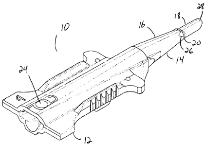
FIG. 1 is an enlarged top perspective view of the lens delivery system
cartridge of
the present invention.
FIG. 2 is an enlarged top perspective view of the distal nozzle of the lens
delivery
system cartridge of the present invention.
FIG. 3 is an enlarged side elevational view of the distal nozzle of the lens
delivery
system cartridge of the present invention.

Page 2


CA 02623752 2008-02-29

~ ~.
Re: 3161 US

Detailed Description of the Preferred Embodiments

As best seen in FIGS. 1-3, lens cartridge 10 of the present invention
generally
includes body 12 and nozzle 14. Cartridge 10 can be molded from any suitable
thermoplastic, such as polypropylene, and the thermoplastic may contain a
lubricity
enhancing agent such as those disclosed in U.S. Pat. No. 5,716,364, the entire
contents of
which are incorporated herein by reference. Nozzle 14 may be integrally formed
with
body 12. Nozzle 14 has a tapered portion 16 and a straight portion 18.
Straight portion
18 has very thin walls, on the order and between 0.07 mm and 0.17 mm thick and
preferably is tubular and of substantially constant round, oval or elliptical
cross-section,
with a cross-sectional area of between around 1.0 mm2 to around 2.6 mm2.
Straight
portion 18 is preferably on the order of 3 mm to 5 mm long so as to allow
cartridge 10 to
deliver IOL 24 inside the capsular bag without tapered portion 16 entering the
incision.
Such a construction does not enlarge the incision during IOL insertion.
Transition area
between tapered portion 16 and straight portion 18 contain reinforcing gusset
22.
Reinforcing gusset 22 helps prevent splitting of nozzle 14 at transition area
20.
Located on the proximal side of transition area 20, at the distal end of
tapered
portion 16 are raised flow leaders 26. Flow leaders 26 help direct the flow of
material
20 during injection molding of cartridge 10 to 12:00 o'clock position 28, then
downwardly
around straight portion 18, causing the weld line to form at 6:00 o'clock
position 30. The
inventors have surprisingly discovered that maximum stress in straight portion
18 occurs
around 12:00 o'clock position 28, while minimum stress in straight portion 18
occurs
around 6:00 o'clock position 30. Directing the weld line of the material flow
to 6:00
o'clock position 30 places the weakest position of straight portion 18 at the
location of
minimal stress, thereby helping to reduce splitting of straight portion 18
during IOL
injection.
While certain embodiments of the present invention have been described above,
these descriptions are given for purposes of illustration and explanation.
Variations,
changes, modifications and departures from the systems and methods disclosed
above
may be adopted without departure from the scope or spirit of the present
invention.

Page 3

Representative Drawing
A single figure which represents the drawing illustrating the invention.
Administrative Status

For a clearer understanding of the status of the application/patent presented on this page, the site Disclaimer , as well as the definitions for Patent , Administrative Status , Maintenance Fee  and Payment History  should be consulted.

Administrative Status

Title Date
Forecasted Issue Date 2011-01-04
(22) Filed 2008-02-29
Examination Requested 2008-02-29
(41) Open to Public Inspection 2008-10-11
(45) Issued 2011-01-04
Deemed Expired 2020-03-02

Abandonment History

There is no abandonment history.

Payment History

Fee Type Anniversary Year Due Date Amount Paid Paid Date
Request for Examination $800.00 2008-02-29
Application Fee $400.00 2008-02-29
Maintenance Fee - Application - New Act 2 2010-03-01 $100.00 2010-02-05
Final Fee $300.00 2010-10-20
Maintenance Fee - Patent - New Act 3 2011-02-28 $100.00 2011-01-31
Maintenance Fee - Patent - New Act 4 2012-02-29 $100.00 2012-01-30
Maintenance Fee - Patent - New Act 5 2013-02-28 $200.00 2013-01-09
Maintenance Fee - Patent - New Act 6 2014-02-28 $200.00 2014-01-08
Maintenance Fee - Patent - New Act 7 2015-03-02 $200.00 2015-02-04
Maintenance Fee - Patent - New Act 8 2016-02-29 $200.00 2016-02-04
Maintenance Fee - Patent - New Act 9 2017-02-28 $200.00 2017-02-08
Maintenance Fee - Patent - New Act 10 2018-02-28 $250.00 2018-02-07
Maintenance Fee - Patent - New Act 11 2019-02-28 $250.00 2019-02-07
Registration of a document - section 124 2019-12-18 $100.00 2019-12-18
Owners on Record

Note: Records showing the ownership history in alphabetical order.

Current Owners on Record
ALCON INC.
Past Owners on Record
ALCON, INC.
BROWN, KYLE
DOWNER, DAVID A.
MUCHHALA, SUSHANT
NOVARTIS AG
TRAN, TU CAM
YAN, DENGZHU
Past Owners that do not appear in the "Owners on Record" listing will appear in other documentation within the application.
Documents

To view selected files, please enter reCAPTCHA code :


To view images, click a link in the Document Description column. To download the documents, select one or more checkboxes in the first column and then click the "Download Selected in PDF format (Zip Archive)" or the "Download Selected as Single PDF" button.

List of published and non-published patent-specific documents on the CPD .

If you have any difficulty accessing content, you can call the Client Service Centre at 1-866-997-1936 or send them an e-mail at CIPO Client Service Centre.


Document
Description 
Date
(yyyy-mm-dd) 
Number of pages   Size of Image (KB) 
Abstract 2008-02-29 1 11
Description 2008-02-29 3 141
Claims 2008-02-29 1 21
Drawings 2008-02-29 2 20
Representative Drawing 2008-09-15 1 11
Cover Page 2008-09-29 1 38
Description 2010-04-23 4 172
Claims 2010-04-23 1 27
Cover Page 2010-12-15 1 38
Assignment 2008-02-29 5 96
Prosecution-Amendment 2008-08-27 1 30
Prosecution-Amendment 2009-10-27 2 87
Prosecution-Amendment 2010-04-23 6 219
Correspondence 2010-10-20 1 35