Note: Descriptions are shown in the official language in which they were submitted.
CA 02623976 2008-03-26
WO 2007/037698 PCT/N02006/000332
1
A DEVICE FOR CLEANING AND DOPING EQUIPMENT FOR THREADS
This invention regards cleaning and doping equipment for
threads. More particularly, it regards cleaning and doping
equipment for threads of the type used to join pipes to a
pipe string, particularly in connection with petroleum
production, and where cleaning fluid and dopes are sprayed at
the thread at a relatively high pressure, with at least one
nozzle and one injection pump being arranged in a power tong.
When joining threaded drill pipes, the threads are typically
doped. Besides facilitating the coupling and uncoupling of
pipes, the purpose of applying dope is to seal the threaded
connection between the box and the pin when this is subjected
to the relatively high fluid pressures that occur during
drilling. Advantageously the corresponding threaded portions
are cleaned by means of e.g. a cleaning fluid prior to the
application of dope (lubricant). Advantageously any residual
cleaning fluid is removed from the threaded portions after
cleaning.
Advantageously the cleaning and doping take place as a pipe
is screwed onto the pipe string, and so obviously the
cleaning fluid and dope are supplied via nozzles mounted in
close proximity to the pipe string, and particularly on or by
the gripping jaws of the so-called power tong.
CA 02623976 2008-03-26
WO 2007/037698 PCT/N02006/000332
2
when joining the pipes, an internally (female) threaded box
portion at the upper end portion of the pipe string projects
up through the lower section of the power tong, the so-called
reaction section. The pipe string is held still during the
joining.
The lower portion of the pipe to be joined to the pipe string
is brought down into the upper section of the power tong, the
so-called make-up section, and is clamped immediately above
the upper portion of the pipe string with a male thread pin
facing the box of the pipe string.
For joining, the pipe is rotated by rotating the make-up
section. During this rotation fixed nozzles in close
proximity to and below the make-up section will provide a
sufficient and continuous supply of cleaning fluid and dope
to the male pin threads of the pipe.
For cleaning and doping (lubrication) of the female box
threads of the stationary pipe string it is preferable to
have a nozzle that moves around the central axis of the pipe
string, e.g. by a set of nozzles being mounted on the
rotatable make-up section. The obvious arrangement is to
supply cleaning fluid and dope from stationary reservoirs
externally of the power tong, via a swivel device that is
known per se, to the nozzles on the rotatable make-up
section. Sealing means prevent leakage of fluid between
rotary and stationary swivel components, which is a demanding
task, particularly in the case of the cleaning fluid, which
is conveyed at a high pressure.
The object of the invention is to remedy or reduce at least
one of the drawbacks of prior art.
The object is achieved in accordance with the invention,
through the features specified in the description below and
CA 02623976 2008-03-26
WO 2007/037698 PCT/N02006/000332
3
in the following claims.
The invention regards a device for cleaning and doping
equipment for threads of the type used to join pipes to a
pipe string, particularly in connection with petroleum
production, where cleaning fluid and dope are sprayed at the
threads at a relatively high pressure, from at least one
nozzle mounted at least in the rotatable make-up section of a
power tong, at least one injection pump arranged to supply
cleaning fluid or dope to the at least one nozzle being
located in the rotatable make-up section.
Preferably a supply line to the at least one injection pump
is arranged to be connected for fluid communication with a
reservoir for cleaning fluid or dope when the make-up section
of the power tong assumes an inactive idle position.
Advantageously the cleaning fluid and dope reservoirs are
pressurized.
Preferably the driving device of the at least one injection
pump is in fluid communication with a hydraulic pressure
system that is integrated into the rotatable make-up section,
and which has no connection to the non-rotatable sections of
the power tong.
Preferably the fluid communication between the driving device
of the at least one injection pump and the hydraulic pressure
system of the rotatable make-up section is sequential and
controlled by the movement of the power tong, by one or more
actuators or a combination of these.
Advantageously the rotatable make-up section of the power
tong is provided with at least one compressed-air nozzle in
fluid communication with a compressed-air accumulator located
in the rotatable make-up section.
CA 02623976 2008-03-26
WO 2007/037698 PCT/N02006/000332
4
Preferably the fluid communication between the at least one
compressed-air nozzle of the rotatable make-up section of the
power tong and the compressed-air accumulator is sequential
and controlled by the cleaning fluid injection pump.
Advantageously a supply line to the compressed-air accumu-
lator is arranged to be connected for fluid communication
with a source of compressed-air when the make-up section of
the power tong assumes an inactive idle position.
The following describes a non-limiting example of a preferred
embodiment illustrated in the accompanying drawings, in
which:
Fig. 1 is a partially sectioned side view of a nozzle and
pump arrangement in a power tong according to the
invention; and
Fig. 2 is a schematic diagram showing a general arrange-
ment according to the invention, schematically
showing nozzles, pumps, driving means, and fluid
accumulators, reservoirs and sources, as well as
valves.
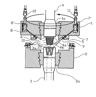
In the drawings, reference number 1 denotes the rotatable
make-up section of a power tong, while the reaction section
of the power tong is denoted by reference number 2.
An upper box shaped end portion 3a of a pipe string 3 is
clamped by the gripping jaws 2a of the reaction section 2, in
a manner that is known per se. The box portion 3a has female
threads 3b.
A pin shaped lower end portion 4a of a pipe 4 is clamped by
gripping jaws la of the make-up section 1, in a manner that
is known per se. The pin portion 4a has male threads 4b that
CA 02623976 2008-03-26
WO 2007/037698 PCT/N02006/000332
correspond with the threads 3b of the box portion 3a.
The rotatable make-up section 1 is provided with a first
nozzle 5 for distribution of a cleaning fluid, and which is
connected with the delivery side of a first injection pump 7
in a fluid communicating manner. Similarly, a second nozzle 6
for distribution of a dope is connected with the delivery
side of a second injection pump 8 in a fluid communicating
manner. The nozzles 5, 6 are directed at the female threads
3b of the upper portion of the non-rotating pipe string 3.
The pressure sides of the driving means 7', 8' for the
injection pumps 7, 8 are connected for fluid communication
with a hydraulic system 13, via pressure lines 7a and 8a,
respectively. Suitable for this purpose would be a hydraulic
system in which hydraulic,pressure is provided through the
closing movement of the make-up section in order to grip the
pipe. The pressure lines 7a, 8a are passed via directional
valves 16 and 17, respectively, which may be actuated by a
vertical movement of the make-up section 1 or a combination
of the vertical movements of the actuator 18 and the make-up
section 1 bringing an annular actuator 18 located above and
parallel to the make-up section 1 into contact with the
directional valve 16, 17 and actuating this. The return sides
of the driving means of the cleaning fluid and dope pumps 7,
8 are connected for fluid communication with the pressure
side of the driving means via return lines 7b and 8b,
respectively, pressure lines 7a and 8a, respectively, and
directional valves 16 and 17, respectively, when the
directional valves 16, 17 are not actuated by the actuator 18
or the make-up section 1 or by a combination of the vertical
movement of the actuator 18 and the make-up section 1.
The make-up section 1 is also provided with a compressed-air
accumulator 20 connected in fluid communication with a
CA 02623976 2008-03-26
WO 2007/037698 PCT/N02006/000332
6
compressed-air nozzle via compressed-air lines 20a and a
directional valve 24. The directional valve 24 is connected
to the cleaning fluid pump 7 via a actuator 24a, so that when
the driving means of the cleaning fluid pump 7 reaches a
predetermined stage in the pump drive cycle, e.g. when it
reaches the limit of linear travel of the pump stroke, the
directional valve 24 is opened to allow compressed air to
pass from the accumulator 20 out through the compressed-air
nozzle 25. The volume of the accumulator 20 is sufficient to
supply the compressed-air nozzle 25 with enough compressed
air to remove residual cleaning fluid. The compressed-air
nozzle 25 is directed at the female threads 3b of the upper
portion of the non-rotating pipe string 3.
When the make-up section 1 is stationary and open, the
cleaning fluid pump 7, the dope pump 8 and the accumulator 20
are in fluid communication with a pressurised source 22 of
cleaning fluid, a dope reservoir 21 and a compressed-air
source 23, respectively, via lines 7c, 8c and 20c,
respectively, and quick release couplings 11, 12 and 19,
respectively, located at the interface 15 between the moving
make-up section and a surrounding static power tong
structure. Through this sequential fluid communication
connection the pumps 7, 8 and the accumulator 20 are filled
with a quantity of cleaning fluid, dope and compressed air,
respectively. When the make-up section 1 of the power tong is
moved to grip a pipe 4, the connections between the pumps 7,
8 and the accumulator 20, respectively, and the cleaning
fluid source 22, the dope reservoir 21 and the compressed-air
source 23, respectively, are disconnected by the quick
release couplings 11, 12 and 19 being activated in a manner
that is known per se.
The stationary reaction section 2 is provided with a cleaning
CA 02623976 2008-03-26
WO 2007/037698 PCT/N02006/000332
7
fluid nozzle 9, a dope nozzle 10 and a compressed-air nozzle
(not shown) in permanent fluid communication with the
pressurized source 22 of cleaning fluid, the dope reservoir
21 and the compressed-air source 23, respectively, via
control valves (not shown). The nozzles of the reaction
section 2 are directed at the male threads 4b of the
rotatable pipe 4.
Cleaning fluid and dope are typically supplied to the nozzles
5, 6 at a pressure of the order of 50-60 mPa.
The supply of cleaning fluid, compressed air and dope
directed at the threaded portions 3b, 4b is sequentially
controlled, with the following sequence:
1. The rotation of the make-up section 1 is stopped;
2. The make-up section 1 is opened, the hydraulic system
13 builds up pressure and the quick release couplings
11, 12 and 19 connect the make-up section 1 to the
dope reservoir 21, the cleaning fluid source 22 and
the compressed-air source 23;
3. A pipe 4 is gripped, rotated and lowered towards the
upper portion of the pipe string 3;
4a. The injection pumps 7 and 8 are actuated
sequentially, through remote control of the hydraulic
system 13, to deliver, in sequence, cleaning fluid,
compressed air and dope at the threaded portion 3b of
the non-rotating pipe string 3, through nozzles 5, 25
and 6;
4b. Simultaneously, cleaning fluid, compressed air and
dope is delivered sequentially at the threaded
portion 4b of the rotating pipe 4, through the
CA 02623976 2008-03-26
WO 2007/037698 PCT/N02006/000332
8
respective stationary nozzles of the reaction
section.
5. The pipe 4 is joined to the pipe string 3 by
continued rotation of the make-up section 1 and
lowering of the pipe 4 until a prescribed torque has
been achieved.
The present invention eliminates the need to transfer fluid
via one or more swivel structures, thus simplifying the
maintenance of the power tong, increasing the reliability and
improving the quality of the screwed connections in the pipe
string.