Language selection

Search

Patent 2624239 Summary

Third-party information liability

Some of the information on this Web page has been provided by external sources. The Government of Canada is not responsible for the accuracy, reliability or currency of the information supplied by external sources. Users wishing to rely upon this information should consult directly with the source of the information. Content provided by external sources is not subject to official languages, privacy and accessibility requirements.

Claims and Abstract availability

Any discrepancies in the text and image of the Claims and Abstract are due to differing posting times. Text of the Claims and Abstract are posted:

  • At the time the application is open to public inspection;
  • At the time of issue of the patent (grant).
(12) Patent Application: (11) CA 2624239
(54) English Title: QUICK CONNECT PRESSURE TEST CAP MOUNTED ON A STUBOUT TUBE
(54) French Title: OBTURATEUR D'ESSAI A RACCORD RAPIDE MONTE SUR UN TUBE DE RACCORDEMENT
Status: Dead
Bibliographic Data
(51) International Patent Classification (IPC):
  • F16L 55/115 (2006.01)
(72) Inventors :
  • TURNAU, WILLIAM FRANKLIN, III (United States of America)
  • GREEN, RONALD D. (United States of America)
  • YOURMAN, DERRY (United States of America)
  • KLIMKIEWICZ, KURT (United States of America)
  • MOON, HYUN (United States of America)
(73) Owners :
  • BRASSCRAFT MANUFACTURING COMPANY (United States of America)
(71) Applicants :
  • BRASSCRAFT MANUFACTURING COMPANY (United States of America)
(74) Agent: PIASETZKI NENNIGER KVAS LLP
(74) Associate agent:
(45) Issued:
(22) Filed Date: 2008-03-05
(41) Open to Public Inspection: 2008-09-08
Examination requested: 2010-07-19
Availability of licence: N/A
(25) Language of filing: English

Patent Cooperation Treaty (PCT): No

(30) Application Priority Data:
Application No. Country/Territory Date
60/905,689 United States of America 2007-03-08

Abstracts

English Abstract


A pressure cap assembly snaps onto a stubout tube in a plumbing supply
system through a quick connect coupling. The pressure cap assembly may include

two parts, with the first part snap fitting to the stubout tube and a second
part snap
fitting to the first part.


Claims

Note: Claims are shown in the official language in which they were submitted.


CLAIMS

1. A pressure cap for a stubout tube comprising:
a pressure cap assembly having a closed end and a bore to be received on a
stubout, said closed end closing off the stubout tube such that a pressure
test can
occur; and
said pressure cap assembly having a quick connect structure such that it can
snap onto a stubout tube.


2. The pressure cap as set forth in Claim 1, wherein a radially inwardly
extending barb on said pressure cap assembly is for snapping into a groove in
an
outer periphery of the stubout tube.


3. The pressure cap as set forth in Claim 1, wherein said pressure cap
assembly
includes two housing parts, with a first housing part having a snap end
connection to
snap onto a stubout tube, and a second housing part snapping onto said first
housing
part.


4. The pressure cap as set forth in Claim 3, wherein one of said first and
second
housing parts has a radially extending shoulder, and the other has a groove,
with said
shoulder snapping into said groove.


5. The pressure cap as set forth in Claim 4, wherein said second housing part
has the groove and said shoulder on said first housing part snaps into said
groove.


6. The pressure cap as set forth in Claim 4, wherein said groove and said
shoulder extend over only a limited circumferential extent.


7. The pressure cap as set forth in Claim 3, wherein a seal is received
between
said first and second housing parts.


4


8. The pressure cap as set forth in Claim 3, wherein one of said fust and
second
housing parts has a barb which extends into a groove on the other of said
first and
second housing parts to prevent relative rotation.


9. The pressure cap as set forth in Claim 8, wherein the barb is formed on
said
first housing part, and extends into the groove in said second housing part.


10. The pressure cap as set forth in Claim 1, wherein a slot is provided to
assist
in removing the pressure cap from a stubout tube.


11. A system comprising:
a stubout tube;
a pressure cap assembly having a closed end and a bore to be received on the
stubout tube, said closed end closing off the stubout tube such that a
pressure test
can occur; and

said pressure cap assembly having a quick connect structure that is snapped
onto the stubout tube.


12. The system as set forth in Claim 11, wherein a radially inwardly extending

barb on said pressure cap assembly snaps into a groove in an outer periphery
of the
stubout tube


13. The system as set forth in Claim 11, wherein said pressure cap assembly
includes two housing parts, with a first housing part having a snap end
connection
snapped onto the stubout tube, and a second housing part snapped onto said
first
housing part.


14. The system as set forth in Claim 13, wherein one of said first and second
housing parts has a radially extending shoulder, and the other has a groove,
with said
shoulder snapped into said groove.


15. The system as set forth in Claim 14, wherein said second housing part has
the groove and said shoulder snaps on said first housing part is snapped into
said
groove.


16. The system as set forth in Claim 15, wherein said groove and said shoulder

extend over only a limited circumferential extent.


17. The system as set forth in Claim 13, wherein a seal is received between
said
first and second housing parts.


18. The system as set forth in Claim 13, wherein one of said first and second
housing parts has a barb which extends into a groove on the other of said
first and
second housing parts to prevent relative rotation.


19. The system as set forth in Claim 18, wherein the barb is formed on said
first
housing part, and extends into the groove in said second housing part.


20. The system as set forth in Claim 11, wherein a slot is provided to assist
in
removing the pressure cap from a stubout tube.


6

Description

Note: Descriptions are shown in the official language in which they were submitted.


CA 02624239 2008-03-05

QUICK CONNECT PRESSURE TEST CAP
MOUNTED ON A STUBOUT TUBE
RELATED APPLICATIONS
The application claims priority to U.S. Provisional Application No.
60/905,689 which was filed on March 8, 2007.

BACKGROUND OF THE INVENTION
This application relates to a pressure test cap which can be attached to a
stubout tube in a water supply system through a quick connect coupling.
Water supply systems typically are provided with a stubout tube that extends
through a wall of a building. Various fluid connections are then made to the
stubout
tube, such as to deliver water to a faucet, etc.
During rough installation of this plumbing system, the integrity of the
roughed in plumbing must be tested. Ends of the stubout tubes must be capped
to
perform this testing.
In the past, a special cap has been installed on each stubout, then removed
for final installation of the plumbing fixtures. This practice can be quite
labor
intensive.
More recently, the stubout tubes have been provided with quick connect fluid
couplings for the connection to the plumbing fixtures. The stubout tubes have
been
provided with an annular groove in the outer surface to receive the quick
connect
couplings.

SUMMARY OF THE INVENTION
In the disclosed embodiment of this invention, a pressure cap is connected to
a stubout tube through a quick connect coupling. In an embodiment, the
pressure
cap includes at least two housing portions, with a cap housing and a cap body.
The
cap housing includes an inner shoulder which is received in the annular
groove, and
the cap body snaps to the cap housing. An intermediate seal may be positioned
between these two portions to complete the seal. The three components may be
preassembled and then attached to a stubout tube.

1


CA 02624239 2008-03-05

These and other features of the present invention can be best understood
from the following specification and drawings, the following of which is a
brief
description.

BRIEF DESCRIPTION OF THE DRAWINGS
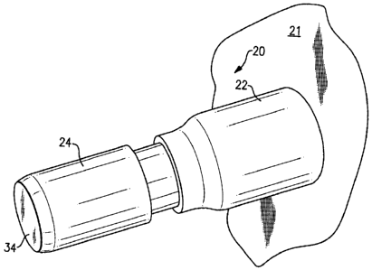
Figure 1 shows an assembled pressure test cap and stubout.
Figure 2 is a cross-sectional view of the pressure test cap.
Figure 3 is an exploded view of the pressure test cap.
Figure 4 shows a first step in removing the pressure test cap.
Figure 5 shows a subsequent step in the removal.
Figure 6 shows yet another step.
Figure 7 shows yet another step.
Figure 8 shows a final step.

DETAILED DESCRIPTION OF THE PREFERRED EMBODIMENT
Figure 1 shows a wall 21 having an extending stubout tube 22 as part of a
plumbing assembly 20. As is known, during rough construction, a pressure test
must be provided on an overall plumbing assembly and thus a cap must be placed
on
the stubout tube. In Figure 2, the inventive cap 24 is shown having an end 34
that
closes off the stubout tube 22.
As shown in Figure 2, the pressure test cap includes a cap housing 28 having
a radially inwardly extending barb 30 which snaps into a groove 26 in the
outer
periphery of the stubout tube 22. A second housing portion 33 snaps onto the
cap
housing 28, as will be explained with regard to Figure 3. A seal 32 is
captured
between the stubout tube 22 and the housing 33.
In practice, the cap housing 28 is assembled with the seal 32 and the second
housing portion 33, and shipped as a preassembled unit. Then, the preassembled
unit may be snapped on to a stubout tube.
As can be appreciated from Figure 3, the cap housing 28 has radially
outwardly extending barbs 38 that are received within a groove 40 in the
second
housing portion 33 to prevent relative rotation. This can be seen in Figure 2
also.

2


CA 02624239 2008-03-05

An opening 36 in the second housing portion 33 receives barbs 39, to secure
the two housing portions together.
A slot 41 will assist in removing the pressure test cap, as will be explained
below. A thumb portion 39 is also provided to assist in removal.
As can be appreciated from Figures 4-8, an initial step of removing the
pressure test cap is to insert a screwdriver 42 into the slot 41. The
screwdriver can
then be pivoted or turned to crack the second housing portion 33, and as shown
at 50
in Figure 5, with a portion 52 moving away from the stubout tube 22, as the
second
housing portion 33 breaks.
As shown in Figure 6, this then leaves the cap housing 28. The cap housing
28 is removed by applying force on the thumb portion 39 to pivot the barb 38
outwardly of the recess 26. The cap housing is then removed as can be
appreciated
from Figure 8.
Although an embodiment of this invention has been disclosed, a worker of
ordinary skill in this art would recognize that certain modifications would
come
within the scope of this invention. For that reason, the following claims
should be
studied to determine the true scope and content of this invention.

3
Representative Drawing
A single figure which represents the drawing illustrating the invention.
Administrative Status

For a clearer understanding of the status of the application/patent presented on this page, the site Disclaimer , as well as the definitions for Patent , Administrative Status , Maintenance Fee  and Payment History  should be consulted.

Administrative Status

Title Date
Forecasted Issue Date Unavailable
(22) Filed 2008-03-05
(41) Open to Public Inspection 2008-09-08
Examination Requested 2010-07-19
Dead Application 2013-03-05

Abandonment History

Abandonment Date Reason Reinstatement Date
2012-03-05 FAILURE TO PAY APPLICATION MAINTENANCE FEE

Payment History

Fee Type Anniversary Year Due Date Amount Paid Paid Date
Application Fee $400.00 2008-03-05
Maintenance Fee - Application - New Act 2 2010-03-05 $100.00 2010-02-03
Request for Examination $800.00 2010-07-19
Maintenance Fee - Application - New Act 3 2011-03-07 $100.00 2011-03-01
Owners on Record

Note: Records showing the ownership history in alphabetical order.

Current Owners on Record
BRASSCRAFT MANUFACTURING COMPANY
Past Owners on Record
GREEN, RONALD D.
KLIMKIEWICZ, KURT
MOON, HYUN
TURNAU, WILLIAM FRANKLIN, III
YOURMAN, DERRY
Past Owners that do not appear in the "Owners on Record" listing will appear in other documentation within the application.
Documents

To view selected files, please enter reCAPTCHA code :


To view images, click a link in the Document Description column. To download the documents, select one or more checkboxes in the first column and then click the "Download Selected in PDF format (Zip Archive)" or the "Download Selected as Single PDF" button.

List of published and non-published patent-specific documents on the CPD .

If you have any difficulty accessing content, you can call the Client Service Centre at 1-866-997-1936 or send them an e-mail at CIPO Client Service Centre.


Document
Description 
Date
(yyyy-mm-dd) 
Number of pages   Size of Image (KB) 
Abstract 2008-03-05 1 8
Description 2008-03-05 3 107
Claims 2008-03-05 3 85
Drawings 2008-03-05 5 101
Representative Drawing 2008-08-18 1 10
Cover Page 2008-08-26 1 37
Correspondence 2008-05-26 2 72
Correspondence 2010-07-20 1 15
Correspondence 2010-07-20 1 18
Prosecution-Amendment 2010-07-19 2 72
Correspondence 2008-04-18 1 17
Assignment 2008-03-05 4 84
Correspondence 2010-06-15 2 54
Correspondence 2014-03-14 31 984
Correspondence 2014-03-24 1 14
Correspondence 2014-03-26 1 27