Note: Descriptions are shown in the official language in which they were submitted.
CA 02624526 2010-05-13
COLLAPSIBLE RING BINDER AND USES THEREOF
BACKGROUND
Field of the Invention
The present invention relates to ring binders adapted to releasably hold
together articles, such
as documents (e.g., sheets of paper, card stock, scrapbook pages, etc.) and
other articles (e.g., media
storage pages, photograph storage pages, etc.) having one or more holes in
locations corresponding to
rings of the ring binder. More particularly, the present invention relates to
binder mechanisms and
collapsible ring binders with rings adapted to be disposed in either an
upright configuration for
holding articles together or a collapsed configuration for flattening the
binder.
Description of Related Art
A ring binder is a device for holding together documents, such as sheets of
paper, for storage,
transport, etc. As known, conventional ring binders generally include a binder
casing having a front
cover, a rear cover and an interconnecting spine. The front cover and the rear
cover are typically
pivotal relative to the spine for providing book-like opening of the binder.
The binder also includes a
binder device, typically a tandem array of two to five rings, that are movable
between an open
configuration and a closed configuration. Documents to be attached to the
binder are typically
provided with a number of holes disposed along one side thereof, which number
generally corresponds
to the number of rings present in the binder device. To attach documents to
the ring binder, a user
opens the rings and passes the rings through the documents' holes. Thereafter
the binder device is
returned to a closed configuration, thereby securely retaining the documents
to the binder.
1
CA 02624526 2008-04-02
WO 2007/044550 PCT/US2006/039203
[0004] Conventional ring binders occupy a large volume of space relative to
the actual dimensions of the
binder. The upright position of the rings of the binder device within the
binder causes conventional binders to be
thick even when empty, especially in the case of larger binders (e.g., binders
with 3, 4, or more inch high rings).
The thicknesses of the binders wastes space in packaging, shipping, retail
display, user storage, and the like.
Regardless of the various packaging schemes employed for conventional binders,
a large amount of space remains
unutilized when a plurality of binders are packaged or stored together.
SUMMARY
[0005] An aspect of one or more embodiments of the present invention provides
a collapsible binder that
includes rings that either flatten into a collapsed position or detach from
the binder, depending on the embodiment.
With the rings collapsed or detached, the binder is significantly flatter,
which facilitates denser packaging of similar
collapsible binders.
[0006] According to a further aspect of one or more of these embodiments, the
collapsing and/or
detachment mechanism is easily operated such that an end user can easily
position the rings in an upright, usable
position to use the binder.
[0007] Additional and/or alternative advantages, objects, and/or salient
features of the invention will
become apparent from the following detailed description, which, taken in
conjunction with the annexed drawings
and claims, disclose preferred embodiments of the invention.
BRIEF DESCRIPTION OF THE DRAWINGS
[0008] Referring now to the drawings which form a part of this original
disclosure:
[0009] FIG. lA is a schematic side view of an exemplary binder device for a
ring binder according to an
embodiment of the present invention, wherein the binder device is in a
collapsed position;
[0010] FIG. 1B is a schematic side view of the exemplary binder device of FIG.
1, wherein the binder
device is in an upright and open position;
[0011] FIG. 1C is a schematic side view of the exemplary binder device of
FIGS. lA-lB, wherein the
binder device is in a neutral position that is also an upright and open
position;
[0012] FIG. 1D is a schematic side view of the exemplary binder device of
FIGS. lA-1C, wherein the
binder device is in an upright, fastened, and closed position;
[0013] FIG. 2 is a perspective view of an exemplary binder using the binder
device of FIGS. lA - 1D,
wherein the binder device is in a collapsed position inside the binder;
[0014] FIG. 3A is a perspective view of an exemplary binder device for an
exemplary ring binder,
wherein the binder device is in a closed, fastened, and upright configuration;
[0015] FIG. 3B is a perspective view of the binder device of FIG. 3A, wherein
the device is in an open,
partially collapsed configuration;
[0016] FIG. 3C is a cross sectional view of the binder device of FIG. 3A,
taken along line A-A thereof;
[0017] FIG. 3D is a perspective view of structural components of the binder
device of FIGS. 3A-3C,
wherein the device is in closed, fastened, and upright configuration;
[0018] FIG. 3E is a perspective view of the binder device of FIG. 3D, wherein
the device is in an upright
configuration;
[0019] FIG. 3F is a perspective view of the binder device of FIGS. 3D and 3E,
wherein the device is in a
collapsed configuration;
2
CA 02624526 2008-04-02
WO 2007/044550 PCT/US2006/039203
[0020] FIG. 3G is a partial perspective view of a binder device of FIGS. 3D
and 3E according to an
alternative embodiment of the present invention;
[0021] FIG. 4A is a perspective view of an exemplary binder using a plurality
of the exemplary binder
device of FIGS. 3A - 3G, wherein the binder devices are in an upright position
inside the binder;
[0022] FIG. 4B is another perspective view of an exemplary binder using a
plurality of the exemplary
binder device of FIGS. 3A - 3G, wherein the binder device is in an upright
position inside the binder;
[0023] FIG. 4C is a perspective view of an exemplary binder using a plurality
of the exemplary binder
device of FIGS. 3A - 3G, wherein the binder device is attached to a base;
[0024] FIG. 4D is a top view of the base shown in FIG. 4C;
[0025] FIG. 4E is a bottom view of the base shown in FIG. 4C;
[0026] FIG. 4F is a perspective view of an exemplary binder using a plurality
of the exemplary binder
device of FIGS. 3A - 3G, wherein the binder device is attached to a base
inside the binder;
[0027] FIG. 5A is a partial perspective view of a binder device;
[0028] FIG. 6A is a partial perspective view of a binder device;
[0029] FIG. 6B is a perspective view of a base of the binder device of FIG.
6A.
[0030] FIG. 7A is a perspective view of an exemplary binding device for a ring
binder, wherein the
binding device is in a closed, fastened, and upright configuration;
[0031] FIG. 7B is a perspective view of the exemplary binding device of FIG.
7A, wherein the binding
device is in an open position;
[0032] FIG. 7C is a bottom perspective view of the exemplary binding device of
FIG. 7B;
[0033] FIG. 7D is an exploded perspective view of the exemplary binding device
of FIGS. 7A-7C;
[0034] FIG. 8A is a perspective view of an exemplary ring binder having a
plurality of the exemplary
binding device of FIGS. 7A-7D associated therewith, and wherein the ring
binder is in an open state and further
wherein the exemplary binding devices are in a closed and upright
configuration;
[0035] FIG. 8B is a side plan view of the ring binder and associated exemplary
binding devices of FIG.
8A;
[0036] FIG. 8C is a perspective of the ring binder and associated exemplary
binding devices of FIGS. 8A
and 8B, wherein the exemplary binding devices are in a collapsed
configuration;
[0037] FIG. 8D is a side plan view of the ring binder and associated exemplary
binding devices of FIG.
8C;
[0038] FIG. 9A is a perspective view of an alternate exemplary ring binder
having a plurality of the
exemplary binding devices of FIGS. 7A-7D associated therewith, and wherein the
ring binder is in an open state
and further wherein the exemplary binding devices are in a closed, fastened,
and upright configuration;
[0039] FIG. 9B is side plan view of the alternate exemplary ring binder and
associated exemplary
binding devices of FIG. 9A, wherein the exemplary ring binder is in a closed
and collapsed state, and further
wherein the exemplary binding devices are in a collapsed configuration;
[0040] FIG. 1 OA is front perspective view of yet another exemplary binding
device for a ring binder
according to the present invention, wherein the binding device is in a closed,
fastened, and upright configuration;
[0041] FIG. l OB is a rear perspective view of the exemplary binding device of
FIG. l OA;
[0042] FIG. 10C is a bottom perspective view of the exemplary binding device
of FIGS. IOA and lOB;
3
CA 02624526 2008-04-02
WO 2007/044550 PCT/US2006/039203
[0043] FIG. 10D is a side perspective view of the exemplary binding device of
FIGS. 10A-10C, wherein
the binding device is in an open state;
[0044] FIG. 10E is a side plan view of the exemplary binding device of FIGS.
10A-10D, wherein the
device is in a closed, fastened, and upright configuration.
[0045] FIG. 11A is a perspective view of an exemplary binder using a plurality
of binder devices of FIGS.
10A - 1 OE, wherein the binder devices are in a collapsed position inside the
binder, the front cover of which is
partially open;
[0046] FIG. 11B is a side view of the binder of FIG. 11A, wherein the binder
devices are in an upright
position inside the binder, the front cover of which is closed;
[0047] FIG. 1 1C is a side view of the binder FIGS. 11A-11B, wherein the
binder devices are in a
collapsed position inside the binder, the front cover of which is closed;
[0048] FIG. 12A is a perspective view of an alternate exemplary binding device
for a ring binder,
wherein the binding device is in a closed, fastened, and upright
configuration;
[0049] FIG. 12B is a perspective view of the alternate exemplary binding
device of FIG. 12A, wherein
the binding device is in an open and upright configuration;
[0050] FIG. 12C is a perspective view of the alternate exemplary binding
device of FIGS. 12A and 12B,
wherein the binding device is in an open and collapsed configuration;
[0051] FIG. 12D is a side plan view of the alternate binding device of FIG.
12C;
[0052] FIG. 12E is a cross sectional view of the alternate binding device of
FIG. 12C, taken along line A-
A thereof;
[0053] FIG. 13 is a side elevational view of an exemplary ring binder using
the exemplary binding device
of FIGS. 12A-12E associated therewith, wherein the ring binder is in a
collapsed configuration;
[0054] FIG. 14A is rear perspective view of yet another exemplary binding
device for a ring binder,
wherein the binding device is in a closed and upright configuration;
[0055] FIG. 14B is a front perspective view of the exemplary binding device of
FIG. 14A;
[0056] FIG. 14C is a front elevational view of the exemplary binding device of
FIGS. 14A-14B;
[0057] FIG. 14D is a side elevational view of the exemplary binding device of
FIGS. 14A-14C;
[0058] FIG. 14E is a top plan view of the exemplary binding device of FIGS.
14A-14D;
[0059] FIG. 14F is a bottom rear perspective view of the exemplary binding
device of FIGS. 14A-14E;
[0060] FIG. 14G is a bottom plan view of the exemplary binding device of FIGS.
14A-14F;
[0061] FIG. 14H is a top perspective exploded view of the exemplary binding
device of FIGS. 14A-14G;
[0062] FIG. 141 is a bottom front perspective exploded view of the exemplary
binding device of FIGS.
14A-14H;
[0063] FIG. 14J is a front perspective view of the exemplary binding device of
FIGS. 14A-14H, wherein
the housing is separated from the binding device;
[0064] FIG. 14K is a bottom rear perspective view of the exemplary binding
device of FIGS. 14A-14J,
wherein the housing is separated from the binding device;
[0065] FIG. 14L is a front perspective view of the exemplary binding device of
FIGS. 14A-14K, wherein
the housing is removed from the binder device;
4
CA 02624526 2008-04-02
WO 2007/044550 PCT/US2006/039203
[0066] FIG. 14M is a rear perspective view of the exemplary binding device of
FIGS. 14A-14L, wherein
the housing is removed from the binder device and the ring is in an open and
upright position;
[0067] FIG. 14N is a rear perspective view of the exemplary binding device of
FIGS. 14A-14M, wherein
the housing is removed from the binder device and the ring is in an open
position;
[0068] FIG. 140 is a rear perspective view of the exemplary binding device of
FIGS. 14A-14N, wherein
the housing is removed from the binder device and the ring is in an open and
collapsed position;
[0069] FIG. 15A is a rear perspective view of the binder device of FIGS. 14A -
140, wherein the binder
device is in a closed, fastened, and upright position inside a binder;
[0070] FIG. 15B is a rear view of the binder device of FIGS. 14A - 140,
wherein the binder device is in a
closed, fastened, and upright position inside a binder;
[0071] FIG. 15C is a rear view of the binder device of FIGS. 14A 140, wherein
the binder device is in a
closed, fastened, and upright position, mounted on a base inside a binder;
[0072] FIG. 15D is a side view of the binder device of FIGS. 14A - 140,
wherein the binder device is in
a closed, fastened, and upright position, mounted on a base inside a binder;
[0073] FIG. 15E is a rear perspective view of the binder device of FIGS. 14A -
140, wherein the binder
device is in a closed, fastened, and upright position, mounted on a base
inside a binder;
[0074] FIG. 15F is a rear view of the binder device of FIGS. 14A - 140,
wherein the binder device is in
an open, collapsed position, mounted on a base inside a binder;
[0075] FIG. 15G is a rear view of the binder device of FIGS. 14A - 140,
wherein the binder device is in
an open, collapsed position, mounted inside a binder;
[0076] FIG. 15H is a rear perspective view of the binder device of FIGS. 14A -
140, wherein the binder
device is in an open, collapsed position, mounted on a base inside a binder;
[0077] FIG. 151 is a rear perspective view of the binder device of FIGS. 14A -
140, wherein the binder
device is in an open, collapsed position, mounted inside a binder;
[0078] FIG. 16A is a another alternate exemplary binding device for a ring
binder according to the
present invention, wherein the binding device is in an open configuration.
[0079] FIG. 16B is a perspective view of the binding device of FIG. 16A,
wherein the device is in a
collapsed configuration;
[0080] FIG. 16C is a perspective view of the binding device of FIGS. 16A and
16B, wherein the binding
device is not securely associated with a stabilizing member;
[0081] FIG. 16D is a perspective view of the binding device of FIG. 16A-16C,
wherein the binding
device is securely associated with the stabilizing member, and further wherein
the binding device is in a closed,
fastened, and upright configuration;
[0082] FIG. 16E is a bottom perspective view of the binding device of FIGS.
16A-16D, wherein a ring
base thereof is in an open state;
[0083] FIG. 16F is a perspective view of the base of the binding device of
FIG. 16E;
[0084] FIG. 16G is a perspective and exploded view of the binding device of
FIGS. 16A-16F,
exemplarily illustrating a ring, the ring base and the stabilizing member
thereof;
CA 02624526 2008-04-02
WO 2007/044550 PCT/US2006/039203
[0085] FIG. 17A is a perspective view of an exemplary ring binder having a
plurality of binding devices
of FIGS. 16A-16G associated therewith, wherein the binding devices are in an
open configuration and further
wherein the ring binder is in an open state;
[0086] FIG. 17B is perspective view of the exemplary ring binder and
associated binding devices of FIG.
17A, wherein the binding devices are in a closed, fastened, and upright
configuration;
[0087] FIG. 17C is a side and partially perspective view of the exemplary ring
binder and associated
binding devices of FIG. 17B.
[0088] FIG. 17D is a perspective view of the of the exemplary ring binder and
associated binding devices
of FIG. 17A, wherein the binding devices are in a collapsed configuration;
[0089] FIG. 17E is a side and partially perspective view of the exemplary ring
binder and associated
binding devices of FIG. 17D;
[0090] FIG. 18A is a perspective view of a binder device, wherein the device
is in an upright and closed
configuration;
[0091] FIG. 18B is a perspective view of the device of FIG. 18A;
[0092] FIG. 18C is a perspective view of the binder device of FIG. 18A,
wherein the device is in an
upright and open configuration;
[0093] FIG. 18D is a perspective view of the binder device of FIGS. 18A-18C,
wherein the device is in a
partially collapsed configuration;
[0094] FIG. 18E is a perspective view of the binder device of FIGS. 18A-18D,
wherein the device is in a
collapsed configuration;
[0095] FIG. 18F is a bottom perspective view of the binder device of FIGS. 18A-
18E;
[0096] FIG. 18G is a perspective view of a portion of the binder device of
FIGS. 18A-18F;
[0097] FIG. 19 is a perspective view of the binder device of FIGS. 18A-18G,
wherein the device is in an
upright and open position inside a binder;
[0098] FIG. 20A is a perspective view of a binder device, wherein the device
is in an upright and closed
configuration;
[0099] FIG. 20B is a bottom perspective view of the binder device of FIG. 20A;
[00100] FIG. 20C is a perspective view of the binder device of FIGS. 20A-20B,
wherein the device is in
an upright and open configuration;
[00101] FIG. 20D is a partial bottom perspective view of the binder device of
FIGS. 20A-20C according
to an embodiment of the present invention;
[00102] FIG. 20E is a cross sectional view of the binder device of FIG. 20D,
taken along line A-A thereof;
[00103] FIG. 21 is a perspective view of the binder device of FIGS. 20A-20E,
wherein the device is in an
upright and closed configuration inside a binder;
[00104] FIG. 22A is a perspective view of an exemplary collapsible three ring
binder device according to
an alternative embodiment of the present invention, shown in a closed
position;
[00105] FIG. 22B is a side view of an exemplary three ring binder that
incorporates the three ring binder
device of FIG. 22A;
[00106] FIG. 22C is a perspective view of the collapsible three ring binder
device of FIG. 22A, shown in
an open position;
6
CA 02624526 2008-04-02
WO 2007/044550 PCT/US2006/039203
[00107] FIG. 22D is an exploded view of a binder ring assembly of the binder
device of FIG. 22A;
[00108] FIG. 22E is a perspective view of the binder ring assembly of FIG. 22D
in a partially
disassembled configuration;
[00109] FIG. 22F is a side view of the binder ring assembly of FIG. 22D in an
open position;
[00110] FIG. 22G is a partial side view of the binder ring assembly of FIG.
22D in a closed position;
[00111] FIG. 22H is a cross-sectional view of the binder ring assembly of FIG.
22D in a closed position;
[00112] FIGS. 221 and 221 are partial perspective views of the binder ring
assembly of FIG. 22D in a
closed position;
[00113] FIG. 23 is a perspective view of an exemplary two-ring binder that
incorporates the binder device
of FIG. 22D according to an alternative embodiment of the present invention.
[00114] FIG. 24A is a perspective view of an exemplary binder ring assembly
according to an alternative
embodiment of the present invention in a closed, upright, and fastened
position;
[00115] FIG. 24B is a perspective view of the binder ring assembly of FIG. 24A
in an open position;
[00116] FIG. 25A is a partial perspective view of an exemplary binder with
three of the binder ring
assemblies of FIG. 24A-24B mounted to the binder; and
[00117] FIG. 25B is a partially disassembled perspective view of the binder of
FIG. 25A.
DETAILED DESCRIPTION OF EXEMPLARY
EMBODIMENTS OF THE INVENTION
[00118] Collapsible ring binders according to various embodiments of the
present invention provide
conventional ring binder functionality (i.e., releasably holding together hole-
punched documents (e.g., sheets of
paper, card stock, scrapbook pages, etc.) and other hole-punched articles
(e.g., media storage pages, photograph
storage pages, etc.) for organized storage, ready access and/or related use).
The ring binders generally include a
casing (e.g., a typically unitary structure with a front cover, a back cover
and a spine interconnecting the covers),
and one or more binder devices secured to the casing. The binder devices maybe
secured to the spine or one of the
covers. If the binder devices are secured to one of the covers, the binder
devices may extend close to or entirely to
the pivotal connection between the cover and the spine. The binder devices
each include a ring configured to
extend through a hole punched or otherwise present in the documents or other
articles. The ring(s) are adapted to
open and close for adding or removing documents. As will also be more fully
explained hereinafter, the binder
device is also configured to collapse to flatten the ring binder for storage,
shipping, retail display and the like.
[00119] FIGS. lA-1D show an exemplary binder mechanism 10, which may be used
in a binder.
Exemplary binder mechanism 10 comprises a base 12 and a ring 14 for securing
documents and other suitable
articles. Exemplary ring 14 comprises a free end 16 and a secured end 18, with
the secured end 18 being movably
secured to the base 12. Base 12 comprises a base connector 20 for fastening
the free end 16 of the ring. In this
exemplary embodiment, the secured end 18 of the ring 14 is movably secured to
the base 12 so as to provide at least
a first degree of freedom (e.g., shown at arrow 22) permitting the ring 14 to
move into an upright position (FIGS.
1B-1D). Also, the secured end 18 of the ring 14 is movably secured to the base
12 so as to also provide at least a
second degree of freedom (e.g., shown at arrow 24) permitting movement of the
free end 16 of the ring toward the
base connector 20 so that the free end 16 of the ring 14 can be fastened to
the base connector 20 with the ring 14
fastened in the upright position (FIG. ID). Thus, FIG. ID may be referred to
as the fastened and upright position of
the ring 14 or the binder mechanism 10. Also, in FIG. 1D the ring 14 or the
binder mechanism 10 may be referred
7
CA 02624526 2008-04-02
WO 2007/044550 PCT/US2006/039203
to as being closed or in a closed configuration; in FIGS. 1A-1C, the ring 14
or the binder mechanism 10 may be
referred to as being open or in an open configuration.
[00120] The ring 14 may be moved from the collapsed position of FIG. 1A into
the fastened and upright
position of FIG. 1D via the positions of FIGS. 1B and 1C. More specifically,
the ring may be moved from the
position of FIG. lA to the position of FIG. 1B, then moved from the position
of FIG. 1B to the position of FIG. 1C,
and then moved from the position of FIG. 1C to the position of FIG. 1D. The
position of FIG. 1C may be just an
intermediate position between the positions of FIGS. 1B and 1D. In the
alternative, the position of FIG. 1C may be
a neutral position or at rest position that the ring 14 assumes naturally
after the free end 16 of the ring 14 is
unfastened from base connector 20 and released. The free end 16 of the ring 14
is spaced from the base connector
20 in the position of FIG. 1C, which may facilitate loading documents or other
articles into a binder utilizing one or
more binder devices 10. The ring 14 maybe spring-biased into the position of
FIG. 1C such that a slight force (or
larger force) is required to move the ring 14 toward either the position of
FIG. 1B or the position of FIG. 1D.
Similarly, the secured end 18 of the ring 14 ring 14 may be coupled to the
base 12 in such a manner that a slight
force (or larger force) is required to move the free end 16 of ring 14 out of
alignment with the base connector 20.
[00121] In this exemplary embodiment, the base 12 may be in one piece or a
plurality of pieces. In FIGS.
1A-1D, the base 12 is shown as two pieces. In many of the other exemplary
embodiments herein, the bases are
shown as one piece, which may be an assembly. Base connector 20 may
permanently fasten the free end 16 of the
ring 14. In the alternative, the connector 20 may releasably fasten the free
end 16 of the ring 14 permitting the free
end 16 of the ring 14 to be repeatedly connected to the base 12 to put the
binder mechanism 10 in a closed
configuration and repeatedly disconnected from the base 12 to put the binder
mechanism 10 in an open
configuration, The secured end 18 of the ring 14 may be movably secured to the
base 12 so that the free end 16 of
the ring 12 can be moved away from the base connector 20 when unfastened.
Additionally, the secured end 18 of
the ring 14 may also be movably secured to the base 12 so that the ring 14 can
be moved out of the upright position
and into a collapsed position (FIG. lA) that significantly reduces the height
of an upper portion 30 of the ring
relative to the base 12.
[00122] The secured end 18 of the ring 14 maybe pivotally connected to the
base 12 via first and second
pivotal connections. Generally speaking, the first pivotal connection may
permit pivotal movement of the free end
16 of the ring 14 away from the base connector 20 and the second pivotal
connection may permit the ring 14 to
pivot into a collapsed position that significantly reduces the height of an
upper portion 30 of the ring 14 relative to
the base 12. Many of the exemplary embodiments herein have such dual pivotal
connections.
[00123] Many different configurations are possible for the base 12, ring 14,
ring free end 16, ring secured
end 18, base connector 20. For example, the base connector 20 may magnetically
fasten the free end of the ring.
Similarly, the base connector 20 may cooperate with the free end 16 of the
ring 14 to form a latch. As another
example, an axis of the ring in the upright position maybe substantially
perpendicular to the axis of the ring in the
collapsed position. The base may comprises a base unit having (a) a portion
movably securing the secured end of
the ring to the base and (b) a portion including the base connector. The ring
may comprise an arcuate portion
between the free end and the secured end. More specifically, the ring may
comprise a unitary U-shaped structure
having the free end and the secured end at opposite ends of the U. The base
connector may be positioned at the end
of a stem extending from the base and rigidly or pivotally affixed to the
base. The base connector 20 may
comprises a keyhole opening having a narrow portion that accepts a narrow
portion at the free end 16 of the ring 14
8
CA 02624526 2008-04-02
WO 2007/044550 PCT/US2006/039203
to fasten the free end 16 of the ring 14 to the base connector 20. The ring 14
may be substantially rigid with the
ability to flex slightly to permit the free end of the ring to be fastened to
and/or unfastened from the base connector
20. The ring 14 may have a circular cross-sectional shape or a different cross-
sectional shape.
[00124] Preferably, but not necessarily, the base connector 20 and the free
end 16 of the ring 14 maybe
configured so that a user desiring to dispose the ring 14 in an upright,
fastened and closed configuration need only
pivot the ring 14 upward, ensure that the ring 14 free end 16 is positioned
generally over the base connector 20, and
push down on the ring 14 (or rotate the ring by its top so the free end 16
moves toward the base connector 20) until
the free end is fastened to the base connector 20, and release the ring.
[00125] In exemplary embodiments herein where the free end 16 of the ring 14
is fastened (directly or
indirectly) to the base 12, the ring(s) may be locked in the upright position
(e.g., 90 degrees or about 90 degrees
with respect to a surface--such as a binder casing portion--supporting the
base) thus giving strength to the structure.
This may be found particularly in mechanisms herein having one or more pivotal
connections between the base and
the secured end of the ring. In all of the embodiments herein with the free
end 16 of the ring 14 fastened to the base
12, the mechanisms may optionally be configured so that the rings in a closed,
fastened, and upright configuration
together can support the weight of a loaded binder standing on edge. Once the
free ends 16 of the rings 14 are
unfastened from the base, they may be weak but when locked (fastened), the
rings may be configured to be firmly
fastened, resisting all directions of force acting on the top of the ring. In
embodiments where the ring 14 is flexed
during fastening, the load that is exerted to fasten the ring may help to lock
the rings in place, permitting the rings to
resist forces in all directions acting on the top of the ring, i.e., the rings
do not become unfastened from the base.
[00126] FIG. 2 shows an exemplary binder 40 comprising a binder casing 42 and
a plurality of binder
mechanisms 10 affixed to the binder casing 42. Each binder mechanism 10 maybe
configured as described above,
or as any of the other binder mechanisms or binder devices described and/or
shown herein. The binder mechanisms
shown in FIG. 2 are in the collapsed position of FIG. 1A. A quick comparison
of the height of an upper portion
30 of the ring relative to the base 12 in FIG. 1A to the height of an upper
portion 30 of the ring relative to the base
12 in any of FIGS. 1B-1D shows how exemplary binder 40 can collapse to a much
thinner configuration than it
would otherwise be able to collapse if the ring 14 were locked in the
positions of any of FIGS 1B-1D.
[00127] The casing 42 of exemplary binder 40 comprises a front cover 44, a
rear cover 46, and an
interconnecting spine 48, all hingedly connected as known to those skilled in
the art. The specific construction of
the casing 42 is not pertinent to the examples herein. Any suitable fastener
(not shown in FIG. 2), such as a rivet, a
screw, an adhesive, and the like, may be employed to secure each binder device
10 to the exemplary binder 40. As
an optional alternative, it may be possible to mold the base or a portion of
the base into position on a surface of the
binder without the ring, and attach the ring and any remaining components of
the base in any suitable means. It
may also is also possible to insert mold the base by molding a cover over some
or all of the metal components
instead of adding the cover as a second part. One, two, three, or more such
devices 10 may be used in exemplary
binder 40. Other structures, such as metal stampings and the like, may
optionally be used to provide additional
support between the binder mechanisms 10 and the binder casing 42. Such
additional structures may be particularly
helpful in supporting rings in binders having relatively tall rings, e.g.,
about 4 inches or taller in the upright and
fastened position.
[00128] FIGS. 3A - 3G illustrate an exemplary binder device 100 according to
an embodiment of the
present invention. As will be more fully described hereinafter, the binder
device 100 is preferably (the term
9
CA 02624526 2008-04-02
WO 2007/044550 PCT/US2006/039203
"preferably" is used herein to indicate exemplary structure of specific
implementations and does not mean
"necessarily") provided as a ring-bearing member adapted to be secured to a
casing either alone or in a tandem
array with other binder devices 100. For example, a casing may suitably
feature a single binder device 100, thereby
providing a single ring binder. By way of additional example, a casing may
suitably feature two or three binder
devices 100, thereby providing a two or three ring binder. The exemplary
binder 100 illustrated is often referred to
as an archival type binder. In general, a binder may be configured to feature
any number of binder devices 100, and
the present invention is not to be construed as limited to the exemplary
arrangements provided herein.
[00129] Each binder device 100 is preferably (but not necessarily) an
independent element. In contrast to
conventional ring binders wherein the rings thereof collectively act together
as a single unit, the illustrated binder
device 100 is actuable (e.g., openable, closable, collapsible, etc.)
separately from adjacent binder devices 100 of a
binder. Thus, with reference to an exemplary casing incorporating three binder
devices 100, when a user wishes to
bind documents together, the user opens each individual binder device 100,
positions the rings through the holes in
each document, and then recloses each individual binder device 100. Similarly,
each binder device 100 is
separately collapsible, as will be more fully described hereinafter.
[00130] With continued reference to FIG. 3A, the binder device 100 generally
includes a binding ring 104
and a ring base 106. The ring 104 is movably secured to the base 106. The ring
104 binds documents to the device
100 by extending through holes formed through the documents. A free end 108 of
the ring 104 engages with the
ring base 106, thereby closing the ring 104 and preventing separation of
documents from the device 100.
Accordingly, the ring 104 is adapted to move relative to the base 106 between
a closed configuration for binding
documents and an open configuration for adding/removing documents to/from the
ring 104. Additionally, the ring
base 106 generally secures the ring 104 to a casing such that the ring 104 may
be opened and closed, and disposed
in either an upright or a collapsed configuration.
[00131] As shown in FIGS. 3C and 3E, the ring 104 is preferably configured as
a generally unitary and
preferably cylindrically cross-sectioned structure having a first end 108, a
second end 110, and an arcuate portion
112 interconnecting the ends 108, 110. Thus, in contrast to rings of
conventional ring binders that typically include
two opposed arcuate structures that move relative to each other, the ring 104
is preferably configured as a unitary
U-shaped structure movable relative to the base 106 as a unit. The use of the
unitary structure of the ring 104
avoids the ring alignment problems associated with some split-ring
conventional binders.
[00132] The first end 108 is generally adapted to releasably engage the ring
base 106 for opening and
closing of the ring 104. The first end 108 may be adapted to engage the ring
base 106 through any suitable
mechanism, preferably a mechanism that permits the first end 108 to repeatedly
engage with and disengage from
the base 106. In a preferred embodiment, the first end 108 includes a
circumferentially reduced portion 114 (e.g.,
an annular groove) that, as described below, is adapted to securely engage a
complementary receiving structure on
the base 106.
[00133] While the first end 108 is adapted to releasably engage the base 106,
the second end 110 is
generally adapted to remain in constant engagement with the base 106 to anchor
the ring 104 to the base 106. As
best shown in FIGS. 3B and 3C, the second end 110 includes a threaded bore 116
extending therein. As will be
more fully explained hereinafter, the bore 116 generally receives a fastener
118 (e.g., a threaded screw, a rivet, etc.)
therein, which secures the ring 104 to the base 106 while allowing the ring
104 to rotate relative to the base 106
CA 02624526 2008-04-02
WO 2007/044550 PCT/US2006/039203
about an axis of the second end 110 (e.g., axis 119). Various aspects of the
second end 110 and the means by which
it remains secured to the base 106 will be more fully described hereinafter.
[00134] Returning to a general discussion of the overall configuration of the
ring 104, the ring 104 is
preferably configured in a generally loop-like or "U" shape that facilitates
manipulation of documents bound in the
device 100. The loop configuration generally provides a path through which the
documents may pass in a book-like
page-turning manner.
[00135] Furthermore, the ring 104 is preferably constructed of a resilient,
somewhat flexible material,
such as a polymer, a metal, spring steel, an alloy, and the like. Thus, in
operation, when the first end 108 and/or
circumferentially reduced portion 114 is engaged with the base 106, the first
end 108 is flexed and/or generally
pulled away from the second end 110 to disengage the first end 108 from the
base 106 and permit opening of the
ring 106. When the first end 108 is released, the ring 104 elastically returns
to its resting state configuration by
virtue of the flexibility of the ring 104. In the alternative, the base may be
configured so that the first end 108 is
generally pulled toward the second end 110 to disengage the first end 108 from
the base 106 and permit opening of
the ring 106.
[00136] The base 106 in this exemplary embodiment is generally rectangular and
includes a structural
member 120 (FIG. 3D) and a housing 122 (FIG. 3B). As will be more fully
explained hereinafter, in this example
the structural member 120 generally enables the functionality of the ring base
106, while the housing 122 is
generally adapted to be disposed about the ring base 106 and increase the
aesthetic appeal of the same. Of course
the base 106 maybe constructed differently and have many different
configurations.
[00137] Turning now to the base 106 structural member 120 and FIG. 3D, the
exemplary structural
member 120 generally includes a ring securing portion 126 and a ring engaging
portion 128. The ring securing
portion 126 is generally a component of the structural member 120 that is
configured to secure the ring 104 and
retain the same to the base 106.
[00138] The exemplary ring securing portion 126 preferably includes a base
portion 130 and a ring
support member 132. The exemplary base portion 130 is generally a structure
adapted to movably support the ring
support member 132. The ring support member 132 is generally a structure to
which the ring 104 is secured. With
continued reference to FIG. 4, the exemplary base portion 130 is provided as a
generally planar member with a
central planar portion 134, a flange 136, and a pair of arcuate portions 138.
The central planar portion 134
generally provides a surface relative to which the ring support member 132
pivots, as will be more fully explained
hereinafter. The flange 136 preferably extends about a front edge and portions
of side edges of the central planar
portion 134, as generally shown in FIG. 3D, and is preferably slightly
vertically offset relative to the central planar
portion 134. The arcuate portions 138 are preferably disposed generally
parallel to the longitudinal axis of the base
106, and extend rearward from terminal portions of the flange 136. The
positioning of the arcuate portions 138
generally creates a channel defined by bottom faces of the arcuate portions
138 and a top face of the central planar
portion 134, in which channel the ring support member 132 is generally
pivotally disposed.
[00139] Turning now to a discussion of the ring support member 132, and as
previously mentioned, the
ring support member 132 generally provides a structure to which the ring 104
is secured, and which enables the ring
104 to move for, e.g., ring 104 opening, closing, collapsing, etc. The ring
support member 132 is preferably "T"
shaped with a transverse bridge 140 and a shoulder 142 extending from a
midportion of the bridge 140 (FIG. 3E).
11
CA 02624526 2008-04-02
WO 2007/044550 PCT/US2006/039203
The bridge 140 is preferably a generally rectangular planar member having a
longitudinal dimension sufficient to
enable opposite ends of the bridge 140 to be disposed within the arcuate
portions 138.
[00140] As shown in FIGS. 3D , 3E, and 3G, a notch 138a is formed in the
bottom face of each of the
arcuate portions 138. As shown in FIG. 3D, when the ring support member 132 is
in its closed position, its bridge
140 extends into the notches 138a, which tends to prevent the ring support
member 132 from sliding relative to the
base 106 when the ring support member 132 is in its closed or open positions.
The notch 138a may act as a pivot
point between the ring support member 132 and the base 106.
[00141] FIGS. 4A-4F show exemplary binders using the exemplary binder device
100 of FIGS. 3A - 3G.
FIG. 4A is a perspective view of an exemplary binder wherein the binder device
100 is in an upright position inside
the binder 160 and the front cover of the binder is closed. FIG. 4B is another
perspective view of the binder device
100, wherein the binder device 100 is in an upright position inside a binder
160 and the front cover is open. FIG.
4C is a perspective view of the binder device 100, wherein the binder device
100 is attached to an optional base 180.
The base 180 may be made of any suitable material, such as stamped metal or
molded plastic. The base 180 may be
secured to the binder 160 by any suitable means, such as a rivet, a screw, an
adhesive, or the like. In addition, the
binding devices 100 may be secured to the base 180 by any suitable means, such
as a rivet, a screw, an adhesive, or
the like. One advantage of the base 180 is to help keep the binding devices
100 stable, particularly for binders
having rings that are 4" or taller in the closed, fastened, and upright
position. In the exemplary embodiment shown,
the base 180 is made out of one piece of stamped metal and comprises flat
portions sized to seat and retain a
plurality of binding devices 100 spaced along its length. Apertures in the
base 180 permit fasteners to pass
therethrough and fasten the devices 100 to the base 180 and the binder 160. In
an alternative embodiment, the
apertures in the base 106 of the binding devices 100, the base 180, and the
binder 160 are aligned so the same
fastener may pass therethrough and fasten the devices 100 to both the base 180
and the binder 160. In another
embodiment, the base 180 is fastened to the binder 160 by fasteners passing
through apertures on each end of the
base 180. As such, the binding devices 100 are fastened to the base 180 by a
separate set of fasteners. FIG. 4D is a
top view of the base 180 shown in FIG. 4C and FIG. 4E is a bottom view of the
base 180 shown in FIG. 4C.
Finally, FIG. 4F is a perspective view of an exemplary binder device 100,
wherein the binder device 100 is attached
to a base 180 inside the binder 160.
[00142] As shown in FIG. 5A, according to an alternative of the embodiment of
FIGS. 3A-3G, a tab 132a
may extend upwardly from the ring support member 132. When the ring support
member 132 is moved into its
open position, the tab 132a abuts the base portion 130 to discourage the ring
support member 132 from pivoting
beyond its open position. The tab 132a helps provide the ring with a slightly
open neutral or at rest position, that
the ring 104 assumes naturally after the free end 108 of the ring 104 is
unfastened from base connector 144, 146 and
released. The free end 108 of the ring 104 is spaced from the base connector
144, 146 in the position of FIG. 3E,
which may facilitate loading documents or other articles into a binder
utilizing one or more binder devices 100.
The ring 104 maybe spring-biased into the position of FIG. 3E such that a
slight force (or larger force) is required
to move the ring 104 toward either the position of FIG. 3B or the position of
FIG. 3D.
[00143] As shown in FIGS. 6A and 6B, according to a further alternative of the
embodiment of FIGS. 3A-
3G, a tab 106a extends upwardly from the base 106. The tab 106a is positioned
to abut the transverse bridge 140
and stabilize the ring support member 132 when the ring support member 132 is
in its closed or open positions. The
tab 106a helps provide the ring with a slightly open neutral or at rest
position, that the ring 104 assumes naturally
12
CA 02624526 2008-04-02
WO 2007/044550 PCT/US2006/039203
after the free end 108 of the ring 104 is unfastened from base connector 144,
146 and released. The free end 108 of
the ring 104 is spaced from the base connector 144, 146 in the position of
FIG. 3E, which may facilitate loading
documents or other articles into a binder utilizing one or more binder devices
100. The ring 104 may be spring-
biased into the position of FIG. 3E such that a slight force (or larger force)
is required to move the ring 104 toward
either the position of FIG. 3B or the position of FIG: 3D.
[00144] Referring back to FIGS. 3B-3E, the exemplary ring support member 132
preferably also includes
the shoulder 142 that extends from a side edge of the bridge 140 and generally
transverse to the longitudinal axis of
the bridge 140. The shoulder 142 is preferably a generally rectangular planar
member that (in this exemplary
embodiment) provides a substrate to which the ring 104, preferably the second
end 110 thereof, is secured. More
specifically, the shoulder 142 preferably includes a bore that permits the
fastener 118 to pass therethrough. As best
shown in FIGS. 3B and 3C, the ring 104 second end 110 is preferably flushly
disposed against the shoulder 142 so
that the second end 110 threaded bore 116 is aligned with the shoulder 142
bore. The fastener 118 preferably
extends through the shoulder 142 bore and into the ring 104 threaded bore 116,
thereby physically securing the ring
104 to the shoulder 142. Accordingly, the fastener 118 connects the ring 104
to the base 106 via the ring support
member 132 and arcuate portion 138.
[00145] According to one embodiment, the fastener 118 and the ring support
member 132 to which it is
attached are provided in a manner that permits the ring 104 to rotate relative
to the base 106 about an axis of the
fastener 118. As will be more fully explained hereinafter, the ring 104 is
collapsible by first disengaging the ring
104 first end 108 from the base 106, pivoting the ring 104 rearward, and then
rotating the ring 104 so that it comes
into general abutting contact with the casing, as shown in FIG. 3F. The use of
a threaded fastener 118 suitably
provides a means by which the ring 104 may rotate relative to the base 106.
However, it is to be appreciated that
any suitable means may be employed for enabling the rotatability of the ring
104. Accordingly, the ring 104 second
end 110 is preferably rotatably retained relative to the shoulder 142 so that
the ring 104 may be repeatedly rotated
relative thereto.
[00146] With continued reference to the ring support member 132, the shoulder
142 and bridge 140 are
preferably provided as a unitary structure. Even more preferably, the shoulder
142 and the bridge 140 are angularly
offset relative to each other. With best reference to FIGS. 3C and 3D, the
bridge 140 is preferably disposed at an
upward angle relative to the shoulder 142. For example, FIG. 3D illustrates
the ring 104 in an upright and closed
configuration in which the shoulder 142 rests in substantially abutting
contact with the central planar portion 134.
In this state, the bridge 140 preferably slopes upward away from the shoulder
142, and is releasably engaged in
notches 138a. Thus, when the ring 104 first end 108 is disengaged from the
base 106 and the ring 104 is pivoted
rearward, the bridge 140 disengages from the notches 138a and begins to rotate
within the arcuate portions 138
along a rotational axis generally parallel to the bridge 140 longitudinal
axis. Thereafter, as the ring 104 continues to
be pivoted rearward, the bridge 142 rotates within the arcuate portion 138
until side faces of the bridge 142
simultaneously contact both the central planar portion 134 and bottom surfaces
of the arcuate portions 138. Further,
the arcuate portions 138 are preferably dimensioned with a vertical profile
that is slightly reduced relative to the
width of the bridge 142, and are also preferably constructed of a flexible
material (e.g., spring steel, etc.).
Accordingly, once the bridge 142 contacts both the central planar portion 134
and the arcuate portions 138, the
relatively reduced vertical profile of the arcuate portions 138 provides an
impediment or resistance to the free
rotation of the bridge 140 relative to the base 106. Applied force to continue
the pivoting of the ring 104 suitably
13
CA 02624526 2008-04-02
WO 2007/044550 PCT/US2006/039203
overcomes the impediment by causing the arcuate portions 138 to flex, thereby
permitting the bridge 140 to
continue its rotation within the arcuate portions 138 and dispose the ring 104
in a fully pivoted and collapsed
configuration. The rotation impediment suitably provides a biasing effect that
urges the ring 104 to remain in either
an upright configuration or a collapsed configuration, absent a force
directing the ring 104 otherwise.
[00147] The structural member 120 also includes the ring engaging portion 128.
As previously
mentioned and as best shown in FIGS. 3B-3D, the ring engaging portion 128
generally provides a structure against
which the ring 104 first end 108 is releasably engageable for ring 104 opening
and closing. In a preferred
embodiment, the ring engaging portion 128 generally includes a face 144 (FIG.
3E) that is angularly offset relative
to the structural member 120, and which face 144 is adapted to engage the ring
104 first end 108 for securely
closing the ring 104. Even more preferably, a front edge of the face 144 is
disposed in proximity to a front portion
of the structural member 120, with the remainder of the face 144 extending
upward therefrom. Additionally, as best
shown in FIG. 3B, the face 144 preferably includes an aperture 146 therein,
into which aperture 146 the ring 104
first end 108 is positionable. In a preferred embodiment, the aperture 146 is
defined by a lower circular portion 150
and an upper channel portion 152' extending from the lower circular portion
150. As such, the aperture 146 has a
keyhole type configuration. As previously mentioned, the ring 104 is
preferably configured generally cylindrically.
Accordingly, in operation, when a user wishes to dispose the ring 104 in an
upright and closed configuration, the
user pivots the ring 104 upward and ensures that the ring 104 first end 108 is
in general proximity to the ring
securing portion 128. Thereafter, the user pulls the first end 108 away from
the second end 110 (suitably possible
because of the flexible nature of the ring 104) and then releases the first
end 108 into the aperture 146 lower circular
portion 150. Again, because of the resilient nature of the ring 104, the first
end 108 rearwardly biases toward the
second end 110, thereby bringing the ring's circumferentially reduced portion
114 within the aperture 146 upper
channel portion 152. When the ring 104 first end 108 is so engaged with the
upper channel portion 152, the ring
104 remains in an upright and closed configuration, thereby preventing release
of documents from the ring 104.
[00148] To disengage the first end 108 from the ring engaging portion 128 so
as to move the ring 104 into
its open position, the user pulls the first end 108 away from the second end
110 so that the first end 108 can be
pulled out of the aperture 146. Alternatively, a release clip may facilitate
disengagement of the first end 108 from
the ring engaging portion 128. Once the free end 108 of the ring 104 is
unfastened from the base, it may be weak
but when locked (fastened), the rings may be configured to be firmly fastened
to the base, resisting all directions of
force acting on the top of the ring. In this exemplary embodiment, the ring
104 is flexed during fastening and the
load that is exerted to fasten the ring may help to lock the ring in place,
permitting the rings to resist forces in all
directions acting on the top of the ring, i.e., the rings to not become
unfastened from the base, as further explained
in the text accompanying the exemplary embodiment of FIGS. 14A-140.
[00149] The binder device 100 structural member 120 preferably also includes
various means that enable
the member 120 to be secured to a binder casing. As best shown in FIG. 3D, the
structural member 120 includes at
least one aperture 148 that permits a fastener, such as a rivet, to pass
therethrough and fasten the device 100 to the
casing. In a preferred embodiment, the member 120 includes an aperture 148
disposed through the central planar
portion 134 thereof, and another aperture 148 disposed through a forward
portion of the member 120, generally in
proximity to the face 144 aperture 146. In this configuration, the fastener
apertures 148 are spaced apart relative to
each other, thereby reinforcing the device 100 against physical dislocation
relative to the casing when secured
thereto.
14
CA 02624526 2008-04-02
WO 2007/044550 PCT/US2006/039203
[00150] Turning to FIGS. 7A-7D, 8A-8D, and 9A-9B, illustrated is another
exemplary embodiment of a
collapsible binding device 200 according to the present invention. By way of
overview, FIG. 7A generally
illustrates the binding device 200 in an upright, fastened, and closed
configuration, while FIG. 7B generally
illustrates the binding device 200 in an open and partially collapsed
configuration. FIG. 8A illustrates a preferred
application of the binding device 200 in which a plurality of collapsible
binding devices 200 are tandemly
associated with a binder 206 to configure the binder 206 as a ringed binder
for removably associating articles, such
as sheets of paper, therewith.
[00151] With best reference to FIGS. 7A and 7D, the exemplary collapsible
binding device 200 preferably
includes a binding ring 202 and a ring base 204, relative to which the ring
202 is movably associated. The ring 202
generally provides a securing means for removably securing documents and other
articles, such as sheets of paper,
to the binder 206, generally in a manner consistent with rings of conventional
ring binders. That is, the ring 202
secures articles to the binder 206 by being disposed in holes in the articles,
with a free end 208 of the ring 202 being
engaged with the ring base 204, thereby closing the ring 202 and preventing
free dissociation of articles from the
binder 206. Accordingly, the ring 202 is adapted to open and close relative to
the base 204 for alternating between
an article-secured configuration and a configuration adapted for associating
and dissociating articles relative to the
ring 202.
[00152] The ring 202 is preferably configured as a generally unitary structure
having the free end 208 that
is associable and dissociable from the base 204 for, inter alia, enabling
removable association of the ring 202 with a
plurality of articles, and a secured end 210 that remains in constant
association with the base 204. Thus, in contrast
to conventional rings of ring binders that typically include two opposed
arcuate structures that move relative to each
other, the ring 202 of the present invention is preferably configured as a
unitary structure movable relative to the
base 204 as a unit. The unitary structure of the ring 202 suitably overcomes
the limitations of conventional rings of
ring binders by eliminating the distortion-based complications of the same.
[00153] In addition to providing opening and closing functionality, the ring
202 is also adapted to collapse.
More specifically, the ring 202 is adapted to alternate between an upright,
fastened configuration for article
securement and an unfastened, collapsed configuration for reducing the size
profile of the binder 206. Aspects of
the collapsibility of the ring 202 will be more fully described hereinafter.
[00154] The free end 208 may be adapted to associate with the ring base 204
through any suitable
mechanism, preferably a mechanism that permits the free end 208 to repeatedly
associate and dissociate with the
base 204. In a preferred embodiment, the free end 208 includes a flange-like
hook 212 angularly protruding
therefrom that fastens to the base. As will be more fully described
hereinafter, the hook 212 is adapted to securely
engage and fasten to complementary receiving structure (a base connector) on
the base 204. The hook 212
preferably extends arcuately from the free end 208 toward the secured end 210
of the ring 202. Additionally, the
ring 202 is preferably constructed of a material, such as a polymer, a metal,
an alloy, and the like, that is relatively
rigid, but that also displays some resilient flexibility required for
fastening the free end of the ring to and
unfastening the free end of the ring from the base (base connector). Thus, in
operation, when the free end 208
and/or hook 212 is engaged with the base 204, the free end 208 is flexed
and/or generally pulled away from the
secured end 210 to disengage the free end 208 from the base 204 and permit
opening of the ring 202. When the free
end 208 is released, the ring 202 returns to its resting state configuration.
CA 02624526 2008-04-02
WO 2007/044550 PCT/US2006/039203
[00155] The secured end 210 of the ring 202 is preferably adapted to be
securely associated with the ring
base 204 and/or an appropriate element thereof. While the free end 208 is
adapted to releasably engage and fasten
to the base 204, the secured end 210 is adapted to remain in constant
association with the base 204 so as to
generally anchor the ring 202 to the base 204. Various aspects of the secured
end 210 and the means by which it
remains in constant association with the base 204 will be more fully described
hereinafter.
[00156] Returning to a general discussion of the overall configuration of the
ring 202, the ring 202 is
preferably configured in a generally loop-like shape that suitably facilitates
manipulation of articles secured to the
device 200. The loop configuration generally provides a path through which the
articles may pass in a book-like
page-turning manner. Also, the ring 202 may suitably be discontinuously
looped. Thus, for example, the ring 202
may include a generally arcuate and looped portion and a generally straight
portion. As best shown in FIGS. 7A
and 7D, the straight portion may suitably extend from the secured end 210 and
gradually transform into the arcuate
portion, which portion terminates in the free end 208. In a preferred
embodiment, the straight portion interfaces
with the arcuate portion at a position slightly below the overall apex of the
ring 202, so that the arcuate portion
defines a substantial portion of the ring 202. The straight portion of the
ring 202 suitably facilitates collapsing of
the ring 202 in manners that will be more fully described hereinafter.
[00157] The collapsible binding device 200 of the present invention suitably
also includes the ring base
204 for, inter alia, associating the ring 202 to the binder 206 and enabling
the preferred multiple functionality (e.g.,
opening and closing, collapsing, and the like) of the ring 202. The base 204
in this example is generally provided as
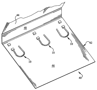
a rectangular member having a bottom surface 224 and a top surface 222. The
bottom surface 224 is generally
planar and rests atop a surface of the binder 206 when the device 200 is
associated therewith. The top surface 222
is disposed in opposition to the bottom surface 224 and has associated
therewith various features that provide the
functionality of the binding device 200 of the present invention.
[00158] With best reference to FIGS. 7A and 7D, the base 204 top surface 222
generally includes a ring
interfacing portion 226 and a ring engaging portion 228. As will be more fully
explained hereinafter, the ring
interfacing portion 226 is a portion of the base 204 adapted for, inter alia,
securing the ring 202 to the base 204 and
for enabling the movability of the ring 202 relative to the base. The ring
engaging portion 222 is suitably a portion
of the base 204 adapted for, inter alia, providing a substrate against which
the free end 208 and/or hook 212 thereof
is releasably secured.
[00159] The ring interfacing portion 226 preferably includes various features
and/or elements that permit
the movability of the ring 202 through a plurality of orientations and
configurations. More specifically, the ring
interfacing portion 226 enables the ring 202 to pivot along its vertical axis
for opening and closing of the ring 202,
and suitably also enables the ring 202 to rotate along the ring 202 secured
end 210 for collapsing of the same.
[00160] Before a preferred embodiment of the ring interfacing portion 226 is
discussed, it is to be
appreciated that any structure and/or elements capable of permitting the
movability of the ring 202 as previously
described may be employed, and that the present invention is not to be
construed as limited to the particular
embodiments of the ring interfacing portion 226 hereinafter described. Turning
to FIGS. 7A, 7B and 7D, the ring
interfacing portion 226 is preferably disposed along an end of the base 204
top surface 222, and generally includes a
shaft 230 rotatably disposed within a pair of engaging arms 232, 234. The
interfacing portion 226 provides a first
pivotal connection to the ring permitting the free end of the ring 208 to move
toward and away from the ring
engaging portion 228. The interfacing portion 226 also provides a second
pivotal connection to the ring permitting
16
CA 02624526 2008-04-02
WO 2007/044550 PCT/US2006/039203
the ring 202 to rotate as shown at arrow 229 (and/or in the opposite
direction) into the collapsed position (e.g., FIGS.
8C-8D and 12D).
[00161] The shaft 230 suitably provides an interfacing element between the
ring 202 and the base 204 that
enables the multiple functionality and movability of the ring 202. The shaft
230 suitably also provides a substrate
to which the ring 202 is mechanically or otherwise secured, and thereby
generally anchors the ring 202 to the binder
206.
[00162] The shaft 230 is preferably provided as a generally right cylindrical
member adapted to rotate,
about its longitudinal axis, within the arms 232, 234. Additionally, the shaft
230 preferably terminates along its
ends in circular end portions that are adapted to be rotatably secured within
complementary receiving structure on
inside surfaces of the arms 232, 234, thereby securing the shaft 230 to the
base 204 and also enabling the free
rotatability of the shaft 230 relative thereto. The association of the ring
202 to the shaft 230 is suitably configured
to enable translation of the shaft's 230 rotation to the ring 202 for
providing openability and closability of the ring
202 relative to the base 204.
[00163] As previously mentioned, the shaft 230 also provides a substrate
against which the ring 202 is
secured. FIGS. 7A-7D illustrate a preferred embodiment of various structure by
which the ring 202 is secured to
the shaft 230. Specifically, the shaft 230 preferably includes a boss-like
receiving channel 236 extending from the
shaft 230 along a midpoint thereof and transversely relative to the
longitudinal axis of the shaft 230. The channel
236 preferably includes an open middle portion in which the secured end 210 of
the ring 202 is received and
secured. The channel 236 is suitably configured in a shape generally
complementary to the cross sectional shape of
the ring 202 to thereby increase the degree of engagement between the ring 202
and the channel 236. The ring 202
may be secured to the channel 236 through any suitable means. In one
embodiment, a fastener, such as a
mechanical fastener (e.g., a screw 240) may suitably be disposed transversely
through a bore 242 of the shaft 230
that extends into association with the secured end 210 of the ring 202. Such
fastener suitably operates to secure the
ring 202 to the base 204 and prevent dissociation of the ring 202 from the
shaft 230. Despite the discussion of the
screw 240, it is to be appreciated that any suitably fastener and/or means for
maintaining the ring 202 in constant
association with the shaft 230 may be employed, such as various insert molding
approaches, swedging, rivets, rivet-
like fasteners and the like.
[00164] As previously mentioned, the ring 202 is preferably adapted to
alternate between an upright and a
collapsed configuration. As contemplated by the present invention, collapsing
of the ring 202 generally involves
first rotation of the shaft 230 away from the base 204 so as to generally
separate the ring 202 free end 208 from the
base 204. The free end 208 is preferably separated from the base 204 until a
portion of the ring 202 generally
proximate to the secured end 210 is disposed in generally abutting
relationship with the binder 206. Once the ring
202 is so disposed, the ring 202 is then generally rotated (e.g., at arrow
229) along an axis coaxial with the ring 202
secured end 210, thereby disposing the length of the ring 202 in generally
abutting relationship with the binder 206
and reducing the vertical size profile of the binding device 200 of the
present invention. Accordingly, the secured
end 210 of the ring 202 is preferably rotatably disposed within the channel
236 to permit rotation of the ring 202
relative to the shaft 230. Therefore, the means by which the ring 202 is
associated with the shaft 230 is preferably a
means, such as an appropriate oriented rivet-like fastener, that permits such
rotatability, even more preferably
frictional rotatability to prevent loose rotation of the ring 202.
17
CA 02624526 2008-04-02
WO 2007/044550 PCT/US2006/039203
[00165] As will be more fully described hereinafter, the binding device 200
preferably includes various
features for biasing the ring 202 into an open position (i.e., a neutral or at
rest position), in which the free end 208
thereof is dissociated from the ring engaging portion 228. More specifically,
the device 200 preferably includes a
biasing means that causes the shaft 230 to rotate away from the ring engaging
portion 228 to thereby separate the
free end 208 from the ring engaging portion 228.
[00166] Relative to the biasing means, the shaft 230 preferably includes a
projection 244 on which the
biasing means acts. More specifically, the projection 244 preferably extends
transversely from the shaft 230 at an
approximate 90 degree angle relative to the receiving channel 236. Various
aspects of the projection 244 will be
more fully described hereinafter in connection with a discussion of the
biasing means.
[00167] The base 204 preferably also includes the arms 232, 234 for rotatably
securing the shaft 230
thereto. The arms 232, 234 are preferably disposed along an end of the base
204 top surface 232, and extend
upward therefrom. Additionally, the arms 232, 234 are preferably spaced apart
and generally parallel relative to
each other so as to define a space therebetween for rotatable disposition of
the shaft 230. Further thereto, the arms
232, 234 preferably include on their inner surfaces (i.e., surfaces of the
arms 232, 234 that face each other and the
space therebetween) shaft-receiving portions and/or features generally
complementary in shape to the ends of the
shaft 230 for securely retaining the shaft 230 therewith.
[00168] The base 204 of the present invention preferably also includes the
ring engaging portion 228 for,
inter alia, releasably engaging the free end 208 of the ring 202. In general,
the ring engaging portion 228 provides a
surface against which the free end 208 and/or hook 212 thereof may engage to
prevent free dissociation of the free
end 208 from the base 204 and to maintain the ring 202 in a closed
configuration.
[00169] In this exemplary embodiment, the ring engaging portion 228 fastens
the free end of the ring to
the base and is preferably disposed atop the base 204 top surface 222 and
generally distal thereon to the ring
interfacing portion 226. The portion 228 preferably includes an aperture-like
opening 250 into which the ring 202
free end 208 suitably is disposed while the ring 202 is in a closed
configuration. The aperture 250 generally
provides a lip-like catch that operates to retain the free end 208 once so
associated.
[00170] Returning to a discussion of the biasing means for biasing the ring
202 into an open configuration,
the collapsible binding device 200 of the present invention preferably, albeit
optionally, includes a bridge 260
adapted to act on the shaft 230 to bias it rotated away from the base 204.
FIG. 7D illustrates a preferred
embodiment of the bridge 260 in which the bridge 260 is configured as a
unitary and ribbon-like member having a
biasing portion 262 and a lip portion 264, both of which are interconnected by
a connecting portion 266. The
biasing portion 262 is preferably configured cross-sectionally in an inverted
letter "U" shaped configuration,
generally terminating in an actuating arm 268. The biasing portion 262 is
preferably constructed of a material, such
as metal, spring steel, and the like, that displays resilient flexibility.
Accordingly, when the actuating arm 268 is
suitably flexed toward the biasing portion 262 (e.g., inward), the actuating
arm 268 tends to spring outward.
[00171] The biasing portion 262 is preferably disposed relative to the base
204 in a manner that causes the
actuating arm 268 thereof to be in abutting contact with the shaft 230. Even
more preferably, the biasing portion
262 is preferably disposed relative to the base 204 in a manner that causes
the actuating arm 268 thereof to be in
abutting contact with the projection 244 of the shaft 230. As best shown in
FIGS. 7B and 7C, the base 204
preferably includes an opening 270 along the ring interfacing portion 226 that
communicates with both the top
surface 222 and the bottom surface 224 of the base 204. The biasing portion
262 of the bridge 260 is preferably
18
CA 02624526 2008-04-02
WO 2007/044550 PCT/US2006/039203
oriented in the opening 270 with its apex penetrably disposed therein.
Accordingly, in this configuration, the
actuating arm 268 is positioned to actively engage the projection 244 of the
shaft 230 and continuously bias the ring
202 into an open configuration.
[00172] Returning to a discussion of the projection 244, the projection 244 is
preferably configured to
receive the biasing of the actuating arm 268 in directing the shaft 230 to
rotate away from the actuating arm 268.
As previously mentioned, the actuating arm 268, through its general letter "U"
shaped configuration, is generally
disposed at a downwardly sloping angle in the base 204 opening 270.
Accordingly, the projection 244 is preferably
configured so as to actively engage the actuating arm 268 and be acted on
thereby. In an exemplary embodiment,
the projection 244, when viewed in cross section, gradually tapers outward and
away from the longitudinal axis of
the shaft 230. Therefore, when the ring 202 free end 208 is dissociated from
the ring engaging portion 228, the
actuating arm 268 suitably applies pressure to the projection 244 and causes
the same to drive the shaft 230 to rotate
away from the ring engaging portion 228, and thereby dispose the ring 202 in
an open configuration. The biasing of
the ring 202 into an open configuration suitably facilitates a user's
interaction with the device 200 by disposing the
free end 208 for ready association with an article, such as a sheet of paper.
[00173] It is to be appreciated that, despite the foregoing discussion, the
biasing means may be provided
as any feature and/or structure capable of biasing the ring 202 into an open
configuration. It is also to be
appreciated that the biasing means is an optional element of the present
invention and may suitably be omitted
therefrom.
[00174] Returning to a discussion of the bridge 260, the bridge suitably also
includes the lip portion 264
for, inter alia, securely engaging the free end 208 and/or hook 212 thereof to
maintain the ring 202 in a closed
configuration. As best shown in FIG. 7D, the lip portion 264 is preferably
fashioned in a manner generally similar
to the biasing portion 262, albeit at reduced dimensions. More specifically,
the lip portion 264 preferably includes a
wall 272 that extends upward from a rear portion of the bridge 260 connecting
portion 266 and which terminates in
a downwardly angled and extended flange-like lip 274. Similar to the
engagement of the base 204 with the biasing
portion 262, the base 204 preferably also includes an opening 276 that
communicates with both the top surface 222
and the bottom surface 224 of the base 204, in which opening 276 the lip
portion 264 is disposed. The lip portion
264 is preferably disposed in the opening 276 in a manner that disposes the
flange-like lip 274 in the aperture 250
for ready engagement with the ring 202 free end 208 and/or hook 212 thereof.
[00175] In operation, the user closes the ring 202 by bringing the free end
208 and/or hook 212 thereof
into engagement with the lip portion 264 of the bridge 260. The free end 208
and/or hook 212 thereof preferably
extends from the ring 202 inward and upward, generally endowing the ring 202,
at least the arcuate portion thereof,
in a generally letter "C" like manner. Thus, when a user pushes the ring 202
into engagement with the lip portion
264, the downward angle of the lip portion 264 suitably assists in orienting
the free end 208 to slide in front of the
lip portion 264 and then thereunder as the flexible material of the ring 202
causes the same to retract. Additionally,
the upward disposition of the free end 208 and/or hook 212 suitably cooperates
with the downwardly angled flange-
like lip 274 to reinforce the fastening engagement between the ring 202 and
the ring engaging portion 228 and
prevent free dissociation of the same.
[00176] FIGS. 8A-8D and 9A-9B illustrate a exemplary applications of the
collapsible binding device 200
of FIGS. 7A-7D, wherein a plurality of the devices 200 are secured to a binder
206 for use in releasably securing
articles, such as sheets of paper, thereto. FIG. 8A illustrates an exemplary
embodiment binder 206 generally
19
CA 02624526 2008-04-02
WO 2007/044550 PCT/US2006/039203
including a front cover 280, a rear cover 282 and a spine 284 interconnecting
the front and rear covers 280, 282 and
providing for the openability of the same, and a plurality of binding devices
200 associated therewith. As evident,
the binder 206 and associated binding devices 200 suitably operate in a manner
generally consistent with
conventional ring binders, wherein the devices 200 provide a means for
releasably securing articles to the binder
206 for organization, storage and the like of the same.
[00177] FIG. 8A illustrates an embodiment in which three binding devices 200
are associated with the
binder 206. However, it is to be appreciated that any desired number of
binding devices 200 may be associated
with a binder. Depending on the size and configuration of the binder 206, and
the general norms and customs of the
society for which it is intended use, the binder 206 may feature any number of
binding devices 200 associated
therewith, such as one, two, three, four, five, and any other convenient and
suitable number. It is also to be
appreciated that any size ring 202 may be employed with the present invention,
such as one inch rings, two inch
rings, three inch rings, four inch rings, five inch or larger rings, and the
like.
[00178] FIG. 8A also illustrates an embodiment in which the binding devices
200 are secured to the rear
cover 282 of the binder 206. It is also to be appreciated that the binding
devices 200 maybe disposed in any
suitable location on the binder 206, given the particular needs and intended
application of the same. Thus, for
example, the devices 200 may suitably be secured to the binder 206 front cover
280, the rear cover 282, the spine
284 or any other manner, directly or indirectly associated therewith.
[00179] It is also to be appreciated that any suitable means may be employed
for securing the binding
devices 200 to the binder 206. In a preferred embodiment, the device 200 base
204 includes a plurality of bores 290
therein, as best shown in FIG. 7B. The bores 290, preferably present in a
paired configuration, are generally
disposed through the base 204 at positions generally between the ring
interfacing portion 226 and the ring engaging
portion 228. Any suitable fastener, such as a rivet, a screw, an adhesive, and
the like, may be employed to secure
the device 200 to the binder 206. As an optional alternative, it may be
possible to mold the base or a portion of the
base into position on a surface of the binder without the ring, and attach the
ring and any remaining components of
the base in any suitable means. It may also is also possible to insert mold
the base by molding plastic material over
some or all of the metal components. In further connection to the preferred
bore 290 embodiment, the device 200 is
preferably secured to the binder 206 through disposition of a rivet (not
shown) in each of the bores 290.
[00180] Returning to an operational discussion of the exemplary device 200,
FIG. 8A illustrates the binder
206 in an open position and with the binding devices 200 in an upright,
fastened, and closed configuration, as if a
plurality of articles were being associated therewith (e.g., held by the
rings). FIG. 8B provides a side illustration of
the binder 206 in a closed position ready for storage on a shelf or similar
element. FIG. 8B particularly illustrates
the width of the binder 206 when the devices 200 are maintained in an upright
configuration, which width is
generally consistent with conventional ring binders.
[00181] FIGS. 8C and 8D particularly illustrate an exemplary benefit of the
collapsible binding device 200
of the present invention. FIG. 8C is an alternate view of the arrangement of
FIG. 8A, wherein the devices 200 are
in a collapsed state, i.e., the free end 208 of the ring 202 is dissociated
from the ring engaging portion 228, the shaft
230 is outwardly rotated to dispose the ring 202 in generally abutting
relationship with the binder 206, and the ring
202 is rotated so as to in its entirety lay flushly against the binder 206.
FIG. 8D provides an alternate view of FIG.
8B. As evident, the width of the binder 206 is substantially decreased by
orders of magnitude when the devices 200
are disposed in the collapsed configuration. As known to one of ordinary skill
in the art, such width decrease
CA 02624526 2008-04-02
WO 2007/044550 PCT/US2006/039203
provides numerous supply chain advantages, such as reduced space requirements
for shipping, retail display,
consumer-based storage and use, and the like.
[00182] FIG. 9A illustrates an alternate embodiment binder 206 that increases
the size profile reduction
aims of the present invention. In this embodiment, the spine 284 of the binder
206 is preferably provided with a
hinge 292 that permits the spine 284 to fold about itself, as generally
illustrated in FIG. 9B. The hinge 292 is
preferably a foldable feature that extends along the entire longitudinal
length of the spine 284, so that when the
devices 200 are collapsed, the spine 284 folds on itself and reduces the
overall width and size profile of the binder
206. Additionally, the hinge 292 is preferably a unidirectional hinge 292 that
permits the spine 284 to only
inwardly (i.e., toward the devices 200) flex. Accordingly, the spine 284 tends
to flex only when the devices 200 are
disposed in the collapsed configuration.
[00183] Turning now to FIGS. 10A-10E, illustrated is yet another alternate
exemplary binding device 300
according to the present invention. The exemplary binding device 300 presents
an alternate configuration of the
previously described binding device 100. Accordingly, it is to be appreciated
that any of the discussion supra of the
binding device 200 and/or various components thereof, is applicable to the
discussion of the binding device 300,
without necessitating any specific reference thereto.
[00184] The discussion of the alternate binding device 300 of FIGS. 1 OA-10E
will be discussed in an
abbreviated format, with regard being given to aspects that generally differ
or are otherwise modified relative to the
previously discussed binding device 200. Turning now to FIG. 10A, the
exemplary binding device 300 generally
includes a ring 302 and a ring base 304. The ring 302 preferably provides the
same functionality as previously
discussed, i.e., it provides a retaining mechanism by which sheets of paper or
similar articles are associated with a
binder or similar device. The ring 302 is preferably provided in any shape
and/or configuration as previously
described. Additionally, in one embodiment, the ring 302 may suitably
terminate in a base engaging portion 306
(FIG. 1 OD) that enables the ring 302 to slidably engage complementary
structure on the base 304. More
specifically and by way of example, the base engaging portion 306 may suitably
feature a circumferentially reduced
portion 308 (FIG. 10D) disposed slightly upstream (i.e., away from the free
end of the ring 302) of a
circumferentially non-reduced portion 310. As will be more fully described
hereinafter, the circumferentially
reduced portion 308 is suitably adapted to interface with a complementary slot-
like receiving portion on the ring
base 304, while the circumferentially non-reduced portion 310 is adapted to
retain the free end of the ring 302 in
engagement with the slot-like receiving portion. The circumferentially non-
reduced portion 310 is preferably
configured in a circumference that generally and/or substantially mirrors the
circumference of the remainder of the
ring 302.
[00185] Turning now to a discussion of the ring base 304, the ring base 304 is
provided as a generally
planar member preferably featuring a ring interfacing portion 312 and a ring
engaging portion 314, similar to the
device 100 discussed above. The ring interfacing portion 312 provides a means
by which the ring 302 is securely
associated with the ring base 304, while the ring engaging portion 314
provides a means by which a free end of the
ring 302 may suitably releasably engage and fasten to the ring base 304 for,
e.g., inserting and/or removing sheets
of paper to the ring 302.
[00186] The ring interfacing portion 312 suitably provides a means by which
the ring 302 remains in
constant engagement with the ring base 304, and which further permits the ring
302 to undergo movement along
several axes, as previously described. With best reference to FIG. 10D, the
ring interfacing portion 312 generally
21
CA 02624526 2008-04-02
WO 2007/044550 PCT/US2006/039203
includes a panel 316 to which the ring 302 is securely associated, in a manner
substantially as described above. In a
different aspect, however, the panel 316 is preferably hingedly associated
(preferably through a living hinge or
other suitable structure) with a rear portion of the ring base 304, thereby
enabling the panel 316 and associated ring
302 to pivot backward, as demonstrated in FIG. 10D. The ring interfacing
portion 312 provides a first pivotal
connection to the ring permitting the free end of the ring to move toward and
away from the ring engaging portion
314. The interfacing portion 312 also provides a second pivotal connection to
the ring permitting the ring to rotate
as shown at arrow 329 (and/or in the opposite direction) into the collapsed
position.
[00187] The ring engaging portion 314 preferably provides a function similar
to the ring engaging portion
228 of the previously described device 200, namely it provides a means for the
free end of the ring 302 to releasably
engage and fasten the ring base 304. With best reference to FIG. 10A, the ring
engaging portion 314 is preferably
provided as having a receiving slot 318 adapted to engage the free end of the
ring -302. More preferably, the slot
318 includes a circumferentially enlarged portion and a tapered portion
therebehind. In operation and as evident
from FIG. 10A, the ring 302 is brought into secure engagement with the ring
engaging portion 314 by disposing the
circumferentially non-reduced portion 310 of the ring 302 in the slot 318
circumferentially enlarged portion (which
disposing may require force to overcome the tension of the ring 302), and
thereafter permitting the ring 302 to adopt
its resting state configuration, whereby the circumferentially reduced portion
308 of the ring 302 slides into the slot
318 tapered portion. In this state, the ring 302 is securely engaged with the
ring base 304 so that any articles (e.g.,
sheets of paper) disposed about the ring 302 will remain associated therewith.
[00188] FIGS. 11A-11C show an exemplary binder 360 using a plurality of the
binder devices 300 of
FIGS. 1 OA-1 OE. FIG. 11A is a perspective view of the exemplary binder 360,
wherein the binder devices 300 are
shown in a collapsed position inside the binder 360 and the cover of the
binder is partially open. FIG. 11B is a side
view of the exemplary binder 360, wherein the binder devices 300 are shown in
an upright position inside the
binder 360 and the cover of the binder 360 is closed. FIG. 11C is a side view
of the binder 360, wherein the binder
devices 300 are shown in a collapsed position inside the binder 360 and the
front cover of the binder 360 is closed.
[00189] Turning to FIGS. 12A-12E, illustrated is another collapsible binding
device 400 according to an
exemplary embodiment of the present invention. The embodiment illustrated in
FIGS. 12A-12E is very similar to
the embodiment illustrated in FIGS. 7A-7D. The differences between the
embodiment of FIGS. 7A-7D and this
embodiment correspond to the ring engaging portion 428 and the ring
interfacing portion 426. With best reference
to FIGS. 12A and 12E, the ring interfacing portion 426 is a portion of the
base 404 adapted for, inter alia, securing
the ring 402 to the base 404 and for enabling the movability of the ring 402
relative to the base 404. The ring
engaging portion 428 is suitably a portion of the base 404 adapted for, inter
alia, providing a substrate against which
the free end 408 and/or hook 412 thereof is releasably secured.
[00190] The ring interfacing portion 426 preferably includes various features
and/or elements that permit
the movability of the ring 402 through a plurality of orientations and
configurations. More specifically, the ring
interfacing portion 426 enables the ring 402 to pivot along its vertical axis
for opening and closing of the ring 402,
and suitably also enables the ring 402 to rotate along the ring 402 secured
end 410 for collapsing of the same.
Turning to FIGS. 12A-12C and 12E, the ring interfacing portion 426 is
preferably disposed along an end of the base
404 top surface 422, and generally includes a shaft 430 rotatably disposed
within a pair of engaging arms 432, 434.
The shaft 430 suitably provides an interfacing element between the ring 402
and the base 404 that enables the
22
CA 02624526 2008-04-02
WO 2007/044550 PCT/US2006/039203
multiple functionality and movability of the ring 402. The shaft 430 suitably
also provides a substrate to which the
ring 402 is mechanically or otherwise secured, and thereby generally anchors
the ring 402 to the binder 406.
[00191] The shaft 430 is preferably provided as a generally right cylindrical
member adapted to rotate,
about its longitudinal axis, within the arms 432, 434. Additionally, the shaft
430 preferably terminates along its
ends in circular end portions that are adapted to be rotatably secured within
complementary receiving structure on
inside surfaces of the arms 432, 434, thereby securing the shaft 430 to the
base 404 and also enabling the free
rotatability of the shaft 430 relative thereto. The association of the ring
402 to the shaft 430 is suitably configured
to enable translation of the shaft's 430 rotation to the ring 402 for
providing openability and closability of the ring
402 relative to the base 404.
[00192] As previously mentioned, the shaft 430 also provides a substrate
against which the ring 402 is
secured. FIGS. 12C and 12E illustrate a preferred embodiment of various
structure by which the ring 402 is secured
to the shaft 430. Specifically, the shaft 430 preferably includes a receiving
channel 436 extending into the shaft 430
along a midpoint thereof and transversely relative to the longitudinal axis of
the shaft 430. The channel 436
receives and secures the secured end 410 of the ring 402. The channel 436 is
suitably configured in a shape
generally complementary to the cross sectional shape of the ring 402 to
thereby increase the degree of engagement
between the ring 402 and the channel 436. The ring 402 may be secured to the
channel 436 through any suitable
fastener and/or means for maintaining the ring 402 in constant association
with the shaft 430, such as various insert
molding approaches, rivet-like fasteners, a screw, and the like. The secured
end 410 of the ring 402 is preferably
rotatably disposed within the channel 436 to permit rotation of the ring 402
relative to the shaft 430. Therefore, the
means by which the ring 402 is associated with the shaft 430 is preferably a
means, such as an appropriate oriented
rivet-like fastener, that permits such rotatability, even more preferably
frictional rotatability to prevent loose
rotation of the ring 402.
[00193] The exemplary binding device 400 preferably includes various features
for biasing the ring 402
into an open position, in which the free end 408 thereof is dissociated from
the ring engaging portion 428. More
specifically, the device 400 preferably includes a biasing means that causes
the shaft 430 to rotate away from the
ring engaging portion 428 to thereby separate the free end 408 from the ring
engaging portion 428. Relative to the
biasing means, the shaft 430 preferably includes a projection 444 on which the
biasing means acts. More
specifically, the projection 444 preferably extends transversely from the
shaft 430 at an approximate 90 degree
angle relative to the receiving channel 436. It is to be appreciated, however,
that the biasing means is an optional
element of the present invention and may suitably be omitted therefrom.
[00194] The base 404 preferably also includes the arms 432, 434 for rotatably
securing the shaft 430
thereto. The arms 432, 434 are preferably disposed along an end of the base
404 top surface 422, and extend
upward therefrom. Additionally, the arms 432, 434 are preferably spaced apart
and generally parallel relative to
each other so as to define a space therebetween for rotatable disposition of
the shaft 430. Further thereto, the arms
432, 434 preferably include on their inner surfaces (i.e., surfaces of the
arms 432, 434 that face each other and the
space therebetween) shaft-receiving portions and/or features generally
complementary in shape to the ends of the
shaft 430 for securely retaining the shaft 430 therewith.
[00195] The base 404 of the present invention preferably also includes the
ring engaging portion 428 for,
inter alia, releasably engaging the free end 408 of the ring 402. In general,
the ring engaging portion 428 provides a
surface against which the free end 408 and/or hook 412 thereof may engage to
prevent free dissociation of the free
23
CA 02624526 2008-04-02
WO 2007/044550 PCT/US2006/039203
end 408 from the base 404 and to maintain the ring 402 in a closed
configuration. The ring engaging portion 428 is
preferably disposed atop the base 404 top surface 422 and generally distal
thereon to the ring interfacing portion
426. The portion 428 preferably includes an aperture-like opening 450 into
which the ring 402 free end 408
suitably is disposed while the ring 402 is in a closed configuration. The
aperture 450 generally provides a lip-like
catch that operates to retain the free end 408 once so associated.
[00196] FIG. 13 illustrates an exemplary binder using the exemplary
collapsible binding device 400. FIG.
13 is a side plan view of the ring binder 406 and the binding device 400,
wherein the binder device 400 is in a
collapsed configuration inside the binder 406. In other words, the free end
408 of the ring 402 is dissociated from
the ring engaging portion 428, the shaft 430 is outwardly rotated to dispose
the ring 402 in generally abutting
relationship with the binder 406, and the ring 402 is rotated so as to in its
entirety lay flushly against the binder 406.
As evident, the width of the binder 406 is substantially decreased by orders
of magnitude when the devices 400 are
disposed in the collapsed configuration. As known to one of ordinary skill in
the art, such width decrease provides
numerous supply chain advantages, such as reduced space requirements for
shipping, retail display, consumer-based
storage and use, and the like. Although the binder devices 400 are shown as
being affixed to the back cover
exemplary binder 426, as with the other exemplary embodiments herein, the
binder device(s) 400 may be secured to
the front cover, the back cover, or the spine of exemplary binders. Similarly,
the front cover, the back cover, and/or
the spine of exemplary binders may be divided into various portions, e.g.,
with hinges.
[00197] FIGS. 14A - 140 illustrate an exemplary binder device 500 according to
an embodiment of the
present invention. As will be more fully described hereinafter, the binder
device 500 is preferably (the term
"preferably" is used herein to indicate exemplary structure of specific
exemplary implementations and does not
mean "necessarily") provided as a ring-bearing member adapted to be secured to
a casing either alone or in a
tandem array with other binder devices 500. For example, a casing may suitably
feature a single binder device 500,
thereby providing a single ring binder. By way of additional example, a casing
may suitably feature two or three
binder devices 500, thereby providing a two or three ring binder. The
exemplary binder mechanism 500 illustrated
may be used in exemplary binders often referred to as archival type binders
(e.g., FIGS. 15A-15E). In general, a
binder may be configured to feature any number of binder devices 500, and the
present invention is not to be
construed as limited to the exemplary arrangements provided herein.
[00198] Each binder device 500 is shown as an independent element. In contrast
to conventional ring
binders wherein the rings thereof collectively act together as a single unit,
the illustrated binder device 500 is
actuable (e.g., openable, closable, collapsible, etc.) separately from
adjacent binder devices 500 of a binder. Thus,
with reference to an exemplary casing incorporating three binder devices 500,
when a user wishes to bind
documents together, the user opens each individual binder device 500,
positions the rings through the holes in each
document, and then re-closes each individual binder device 500. Similarly,
each binder device 500 is separately
collapsible, as will be more fully described hereinafter. In the alternative,
the binder devices may be modified so
that the rings may be closed in unison.
[00199] With continued reference to FIGS. 14A and 14B, the binder device 500
generally includes a
binding ring 504 and a ring base 506. The ring 504 is movably secured to the
base 506. The ring 504 binds
documents and other suitable configured articles (e.g., media storage pages,
photograph storage pages, etc.) to the
device 500 by extending through holes formed through the documents and
articles. A free end 508 of the ring 504
engages with and is fastened to the ring base 506, thereby closing the ring
504 and preventing separation of
24
CA 02624526 2008-04-02
WO 2007/044550 PCT/US2006/039203
documents from the device 500. Accordingly, the ring 504 is adapted to move
relative to the base 506 between a
closed configuration for binding documents and an open configuration for
adding/removing documents to/from the
ring 504. Additionally, the ring base 506 may secure the ring 504 to a casing
(e.g., FIGS. 15A-15E) such that the
ring 504 may be opened and closed, and disposed in either an upright or a
collapsed configuration.
[00200] As shown in FIGS. 14C and 14D, the ring 504 may be configured as a
generally unitary structure
having a first free end 508, a second secured end 510, and an arcuate portion
512 interconnecting the ends 508, 510.
The exemplary ring 504 shown is generally U-shaped and circular in cross-
section. Thus, in contrast to rings of
some conventional ring binders that typically include two opposed arcuate
structures that move relative to each
other, the exemplary ring 504 is preferably configured as a unitary U-shaped
structure movable relative to the base
506 as a unit. The use of the unitary structure of the ring 504 avoids the
ring alignment problems associated with
some split-ring conventional binders.
[00201] The first end 508 is generally adapted to releasably engage and be
fastened to the ring base 506
for opening and closing of the ring 504. The first end 508 may be adapted to
engage the ring base 506 through any
suitable mechanism, preferably a mechanism that permits the first free end 508
to repeatedly engage with (and
fasten to) and disengage from (and be unfastened from) the base 506. In a
preferred embodiment, the first end 508
includes a narrow portion proximate a distal wider portion, such as
circumferentially reduced portion 514 (formed,
e.g., by an annular groove or by one or more channels in the free end of the
ring) that, as described below, is
adapted to securely engage a connector 509 or another complementary fastening
structure on the base 506. More
specifically, the circumferentially reduced portion 514 leaves a distal wider
portion 515 of the free end 508 of the
ring 504, which distal wider portion 515 is fastened in aperture 546.
[00202] While the first free end 508 of the ring 504 is adapted to releasably
engage the base 506, the
second end 510 in this exemplary embodiment is generally adapted to remain in
constant engagement with the base
506 to anchor the ring 504 to the base 506. As best shown in FIGS. 14H-14J, a
fastener 518 (e.g., a threaded screw,
a rivet, etc.) generally secures the second end 510 of the ring 504 to a ring
support member 532. The ring support
member 532 in this exemplary embodiment is "T" shaped with a transverse bridge
540 and a shoulder 542
extending from a midportion of the bridge 540 (FIG. 14H and 141). The fastener
518 allows the ring 504 to rotate
relative to the base 506 about an axis of the second end 510 (e.g., axis 519).
More specifically, in this exemplary
embodiment (as well as all the exemplary embodiments herein), the fastener (or
other connection between the base
and the secured end of the ring) may be configured permit the ring to rotate
relative to the base about an axis of the
secured end of the ring in response to a user grasping the ring and moving the
ring about that axis relative to the
base, but the fastener may secure the ring tightly enough (and/or provide
sufficient friction) to prevent the ring from
moving relative to the base about that axis merely under the force of gravity
acting on the mass of the ring. In the
alternative, swedging may be used in this embodiment (and in the other
embodiments, as appropriate). More
specifically to this embodiment, for example, the second (secured) end 510 of
the ring 504 may be swedged to the
ring support member 532 and provide the functionality mentioned immediately
above with respect to the fastener
holding the ring to the ring support member. In any event, the coupling
between the secured end 510 of the ring
510 and the ring support member 532 may optionally be configured to allow the
ring to swing into position, with
the free end of the ring aligned with the aperture, and then stop in that
desired position to allow fast and easy
alignment. This may be accomplished with a detent (e.g., cooperating
structures on the end 510 of the ring and on
the ring support member) in that position. A detent may be optionally be used
in the open and the two closed
CA 02624526 2008-04-02
WO 2007/044550 PCT/US2006/039203
positions. Any one or more such detents may be used in virtually any of the
embodiments herein. In any event, it
may be desirable to have a certain friction on this joint to allow easy
alignment without the stopping action so the
parts stay in position all together while loading documents or other articles
into a binder and don't move around
while loading. Various aspects of the second end 510 and the means by which it
remains secured to the base 506
will be more fully described hereinafter.
[00203] Returning to a general discussion of the overall configuration of the
ring 504, the ring 504 is
preferably configured in a generally loop-like or "U" shape that facilitates
manipulation of documents bound in the
device 500. The loop configuration generally provides a path through which the
documents may pass in a book-like
page-turning manner.
[00204] Furthermore, the ring 504 is preferably constructed of a resilient,
somewhat flexible material,
such as a polymer, a metal, spring steel, an alloy, and the like. Thus, in
operation, when the first end 508 and/or
circumferentially reduced portion 514 is engaged with the base 506, the ring
is flexed as the first end 508 is moved
or generally pulled away from the second end 510 to disengage the first end
508 from the base 506 and permit
opening of the ring 506. When the first end 508 is released, the ring 504
elastically returns to its resting state
configuration by virtue of the flexibility of the ring 504. In the
alternative, the base may be configured so that the
first end 508 is generally pulled toward the second end 510 to disengage the
first end 508 from the base 506 and
permit opening of the ring 506.
[00205] The base 506 in this exemplary embodiment is generally rectangular and
includes a structural
member 520 (FIGS. 14J-14L) and a housing 522 (FIGS. 14H-14K). As will be more
fully explained hereinafter, in
this example the structural member 520 generally enables the functionality of
the ring base 506, while the housing
522 is generally adapted to be disposed about the ring base 506 and increase
the aesthetic appeal of the same. Of
course the base 506 may be constructed differently and have many different
configurations.
[00206] Turning now to the base 506 structural member 520 and FIGS. 14H and
141, the exemplary
structural member 520 generally includes a ring securing portion 526 and a
ring engaging portion 528. The ring
securing portion 526 is generally a component of the structural member 520
that is configured to secure the ring 504
and retain the same to the base 506.
[00207] The exemplary ring securing portion 526 preferably includes a base
portion 530 and a ring
support member 532. The exemplary base portion 530 is generally a structure
adapted to movably support the ring
support member 532. The ring support member 532 is generally a structure to
which the ring 504 is secured. With
continued reference to FIGS. 14H and 141, the exemplary base portion 530 is
provided as a generally planar
member with a central planar portion 534, a flange 536, and a pair of arcuate
portions 538. The central planar
portion 534 generally provides a surface relative to which the ring support
member 532 pivots, as will be more fully
explained hereinafter. The flange 536 preferably extends about a front edge
and portions of side edges of the
central planar portion 534, as generally shown in FIG. 14H, and is preferably
slightly vertically offset relative to the
central planar portion 534. The arcuate portions 538 are preferably disposed
generally parallel to the longitudinal
axis of the base 506, and extend rearward from terminal portions of the flange
536. The positioning of the arcuate
portions 538 generally creates a channel defined by bottom faces of the
arcuate portions 538 and a top face of the
central planar portion 534, in which channel the ring support member 532 is
generally pivotally disposed. A tab
506a extends upwardly from the central planar portion 534. The tab 506a is
positioned to abut the transverse bridge
540 and stabilize the ring support member 532 when the ring support member 532
is in its closed or open positions.
26
CA 02624526 2008-04-02
WO 2007/044550 PCT/US2006/039203
[00208] Turning now to a discussion of the ring support member 532, and as
previously mentioned, the
ring support member 532 generally provides a structure to which the ring 504
is secured, and which enables the ring
504 to move for, e.g., ring 504 opening, closing, collapsing, etc. The ring
support member 532 is preferably "T"
shaped with a transverse bridge 540 and a shoulder 542 extending from a
midportion of the bridge 540 (FIGS. 14H
and 141). The bridge 540 is preferably a generally rectangular planar member
having a longitudinal dimension
sufficient to enable opposite ends of the bridge 540 to be disposed within the
arcuate portions 538. The exemplary
ring support member 532 preferably also includes the shoulder 542 that extends
from a side edge of the bridge 540
and generally transverse to the longitudinal axis of the bridge 540. The
shoulder 542 is preferably a generally
rectangular planar member that (in this exemplary embodiment) provides a
substrate to which the ring 504,
preferably the second end 510 thereof, is secured. More specifically, the
shoulder 542 preferably includes a bore
that permits the fastener 518 to pass therethrough. As best shown in FIGS. 14H
and 141, the ring 504 second end
510 is preferably flushly disposed against the shoulder 542. The fastener 518
(e.g., a threaded screw, a rivet, etc.)
preferably extends through the shoulder 542 bore and into the ring 504 (e.g.,
into a threaded bore, a non-threaded
bore, etc.), thereby physically securing the ring 504 to the shoulder 542.
Accordingly, the fastener 518 connects the
ring 504 to the base 506 via the ring support member 532 and arcuate portion
538.
[00209] According to one embodiment, the fastener 518 and the ring support
member 532 to which it is
attached are provided in a manner that permits the ring 504 to rotate relative
to the base 506 about an axis of the
fastener 519. As will be more fully explained hereinafter, the ring 504 is
collapsible by first disengaging the ring
504 first end 508 from the base 506, pivoting the ring 504 rearward, and then
rotating the ring 504 so that it comes
into general abutting contact with the casing. The use of a rivet as the
fastener 518 suitably provides a means by
which the ring 504 may rotate relative to the base 506. However, it is to be
appreciated that any suitable means
maybe employed for enabling the rotatability of the ring 504. Accordingly, the
ring 504 second end 510 is
preferably rotatably retained relative to the shoulder 542 so that the ring
504 may be repeatedly rotated relative
thereto.
[00210] With continued reference to the ring support member 532, the shoulder
542 and bridge 540 are
preferably provided as a unitary structure. Even more preferably, the shoulder
542 and the bridge 540 are angularly
offset relative to each other. With best reference to FIGS. 14H-14J and 14L,
the bridge 540 is preferably disposed
at an upward angle relative to the shoulder 542. For example, FIG. 14L
illustrates the ring 504 in an upright and
closed configuration in which the shoulder 542 rests in substantially abutting
contact with the central planar portion
534. In this state, the bridge 540 preferably slopes upward away from the
shoulder 542. Thus, when the ring 504
first end 508 is disengaged from the base 506 and the ring 504 is pivoted
rearward, the bridge 540 begins to rotate
within the arcuate portions 538 along a rotational axis generally parallel to
the bridge 540 longitudinal axis. In
addition, once the first end 508 of the ring 504 is disengaged from the base
506, it will remain suspended at a
certain distance above the base 506 until rotated by the user. This is a
neutral position or at rest position of the ring
504, similar to that discussed above in the context of the exemplary
embodiment of FIGS. 1A-1D. Thereafter, as
the ring 504 continues to be pivoted rearward, the bridge 542 rotates within
the arcuate portion 538 until side faces
of the bridge 542 simultaneously contact both the central planar portion 534
and bottom surfaces of the arcuate
portions 538. Further, the arcuate portions 538 are preferably dimensioned
with a vertical profile that is slightly
reduced relative to the width of the bridge 542, and are also preferably
constructed of a flexible material (e.g.,
spring steel, etc.). Accordingly, once the bridge 542 contacts both the
central planar portion 534 and the arcuate
27
CA 02624526 2008-04-02
WO 2007/044550 PCT/US2006/039203
portions 538, the relatively reduced vertical profile of the arcuate portions
538 provides an impediment or resistance
to the free rotation of the bridge 540 relative to the base 506. Applied force
to continue the pivoting of the ring 504
suitably overcomes the impediment by causing the arcuate portions 538 to flex,
thereby permitting the bridge 540 to
continue its rotation within the arcuate portions 538 and dispose the ring 504
in a fully pivoted and collapsed
configuration. The rotation impediment suitably provides a biasing effect that
urges the ring 504 to remain in either
an upright configuration or a collapsed configuration, absent a force
directing the ring 504 otherwise.
[00211] The structural member 520 also includes the ring engaging portion 528,
which acts as a connector
that fastens the free end of the ring to the base. As previously mentioned and
as best shown in FIGS. 14H-14J and
14L, the ring engaging portion 528 generally provides a structure against
which the ring 504 first end 508 is
releasably fastened for ring 504 opening and closing. In a preferred
embodiment, the ring engaging portion 528
generally includes a face 544 (FIG. 14H) that is angularly offset relative to
the generally horizontal structural
member 520, and which face 544 is adapted to engage the ring 504 first end 508
for securely fastening and thus
closing the ring 504. Even more preferably, a front edge of the face 544 is
disposed in proximity to a front portion
of the structural member 520, with the remainder of the face 544 extending
upward therefrom. Additionally, as best
shown in FIG. 14H, the face 544 preferably includes an aperture 546 therein,
into which aperture 546 the ring 504
first end 508 is fastened. The aperture 546 maybe stamped so as to form a
rounded edge 546a on the top of face
544 (which may help guide the free end 508 of the ring 504 into the aperture
546) and a ridge 546b on the underside
of face 544 (which may help retain the flared distal end 515 of the ring 504).
In a preferred embodiment, the
aperture 546 is defined by a lower wider portion 550--shown here as a circular
portion--and an upper channel
portion 552 that is narrower than the wider portion 550 and that extends from
the lower wider portion 550. As such,
the aperture 546 has what may generally be considered to be a keyhole type
configuration. As previously
mentioned, the ring 504 is preferably configured generally cylindrically.
Accordingly, in operation, when a user
wishes to dispose the ring 504 in an upright and closed configuration, the
user pivots the ring 504 upward and
ensures that the ring 504 first end 508 is in general proximity to the ring
securing portion 528. Thereafter, the user
pulls the first end 508 away from the second end 510 (suitably possible
because of the flexible nature of the ring
504) and then releases the first end 508 into the aperture 546 lower circular
portion 550. The specific aperture 546
shown (FIG. 14H) has a lower portion 550 that accepts the flared distal
portion of the free end 508 and that is
generally a section of a circle that tapers tangentially to an upper portion
552 that engages and fastens the
circumferentially narrower portion and that is generally a section of a
relatively smaller circle. Preferably, but not
necessarily, the face 544 and upper channel portion 552 of the keyhole opening
546 may be configured so that a
user desiring to dispose the ring 504 in an upright, fastened and closed
configuration need only pivot the ring 504
upward, ensure that the ring 504 free end 508 is positioned generally over the
aperture 546, and push down on the
ring 504 (or rotate the ring by its top so the free end moves toward the face
544). In this scenario, as the ring 504 is
pushed down (or rotated), the flared distal end of the free end 508 rides down
the face 544 until a portion of the
flared distal end enters the upper channel portion 522 at which time the
flared distal end rides in the channel thereby
moving the free end 508 away from the secured end 510 as the ring 504 is
pushed further down (or rotated further)
until the flared distal end 515 enters the lower portion 550, at which time,
the ring maybe released with the free end
508 fastened in the closed position by the aperture 546. the distal end 515 of
the free end 508 of the ring 504 may
be rounded or tapered, e.g., at 515a. Again, as the ring is released by the
user, because of the resilient nature of the
ring 504, the first end 508 rearwardly biases toward the second end 510,
thereby bringing the ring's
28
CA 02624526 2008-04-02
WO 2007/044550 PCT/US2006/039203
circumferentially reduced portion 514 within the aperture 546 upper channel
portion 552. When the ring 504 first
end 508 is so engaged with the upper channel portion 552, the ring 504 remains
in an upright and closed
configuration, thereby preventing release of documents from the ring 504.
[00212] To disengage the first end 508 from the ring engaging portion 528 so
as to move the ring 504 into
its open position, the user pulls the first end 508 away from the second end
510 so that the first end 508 can be
pulled out of the aperture 546. Alternatively, a release clip may facilitate
disengagement of the first end 508 from
the ring engaging portion 528.
[00213] The binder device 500 structural member 520 preferably also includes
various means that enable
the member 520 to be secured to a binder casing. As best shown in FIGS. 14F
and 14G, the structural member 520
includes at least one aperture 548 that permits a fastener, such as a rivet,
to pass therethrough and fasten the device
500 to the casing. In a preferred embodiment, the member 520 includes an
aperture 548 disposed through the
central planar portion 534 thereof, and another aperture 548 disposed through
a forward portion of the member 520,
generally in proximity to the face 544 aperture 546. In this configuration,
the fastener apertures 548 are spaced
apart relative to each other, thereby reinforcing the device 500 against
physical dislocation relative to the casing
when secured thereto.
[00214] The ring 504 may be moved from the collapsed position of FIG. 140 into
the fastened and upright
position of FIGS. 14A-14G and 14L via the positions of FIGS. 14N and 14M. More
specifically, the ring maybe
moved from the position of FIG. 140 to the position of FIG. 14N, then moved
from the position of FIG. 14N to the
position of FIG. 14M, and then moved from the position of FIG. 14M to the
upright, fastened, and closed position
of FIGS. 14A-14G and 14L. The position of FIG. 14M in this embodiment is a
neutral position or at rest position
that the ring 504 assumes naturally after the free end 508 of the ring 504 is
unfastened from base connector 544,
546 and released. The distal end 515 of the free end 508 of the ring 504 is
spaced from the base connector 544, 546
in the position of FIG. 14M, which may facilitate loading documents or other
articles into a binder utilizing one or
more binder devices 500. In this embodiment, the ring 504 is spring-biased
into the position of FIG. 14M, as
discussed above, such that a slight force (or larger force) is required to
move the ring 14 toward either the position
of FIG. 14N or the position of FIGS. 14A-14G and 14L. Similarly, the secured
end 510 of the ring 504 maybe
coupled to the base 506 in such a manner that a slight force (or larger force)
is required to move the free end 508 of
ring 504 out of alignment with the base connector 544, 546. The slight forces
(or larger forces) discussed herein are
intended to mean a force stronger than the force gravity applies via the mass
of the ring 504 in the orientation(s)
shown.
[00215] In the exemplary embodiment of FIGS. 14A - 140, the free end 508 of
the ring 504 is fastened to
the base 504 and the ring(s) may be locked in the upright position (e.g., 90
degrees or about 90 degrees with respect
to a surface--such as a binder casing portion--supporting the base) thus
giving strength to the structure. The pivotal
nature of this mechanism provides additional strength to the rings.
Implementations using this embodiment may be
configured so that the rings in a closed, fastened, and upright configuration
together can support the weight of a
loaded binder (e.g., the binders of FIGS. 15A-15I) standing upright on edge.
Once the free ends 508 of the rings
504 are unfastened from the base, they may be weak but when locked (fastened),
the rings may be configured to be
firmly fastened, resisting all directions of force acting on the top of the
ring. In this exemplary embodiment, the
ring 504 is flexed during fastening and the load that is exerted to fasten the
rings may help to lock the rings in place,
permitting the rings to resist forces in all directions acting on the top of
the ring, i.e., the rings to not become
29
CA 02624526 2008-04-02
WO 2007/044550 PCT/US2006/039203
unfastened from the base. From the orientation of FIG. 14D, pushing the top of
the ring down causes the free end
508 to bottom out against the upper surface of the base portion 530; pushing
the top of the ring to the left or pulling
up on the ring urges the narrow portion 514 and wider distal end 515 into
further engagement with the edge of the
narrow portion 552 of the aperture 546; pushing the top of the ring to the
right causes the free end 508 to bottom out
against the upper surface of the base portion 530. Similarly, if binder
mechanism 500 is attached in a binder so that
documents and other articles are located on the side of the ring with the
secured end 510 (the side with axis 519 in
the figures), as shown in FIGS. 15A-151 below, a mass of documents or other
articles would not be able to unfasten
the free end 508 from the base connector 544, 546 by exerting a force against
that side of the ring. Thus, even if a
full binder is stood on end, or even dropped, the rings may stay in the
closed, fastened, and upright configuration.
Other embodiments herein may be implemented with the same functionality.
[00216] FIGS. 15A-15I illustrate exemplary applications of the exemplary
collapsible binding device 500
shown in the FIG. 14 series of figures, wherein a plurality of the devices 500
are secured to a binder 560 for use in
releasably securing articles, such as sheets of paper, thereto. FIGS. 15A and
15B illustrate an exemplary binder 560
generally including a front cover 564, a rear cover 568 and a spine 566
interconnecting the front and rear covers 564,
568 and providing for the openability of the same, and a plurality of binding
devices 500 associated therewith. As
evident, the binder 560 and associated binding devices 500 suitably operate in
a manner generally consistent with
conventional ring binders, wherein the devices 500 provide a means for
releasably securing articles to the binder
560 for organization, storage and the like of the same.
[00217] FIGS. 15A and 15B illustrate an embodiment in which three binding
devices 500 are associated
with the binder 560. However, it is to be appreciated that any desired number
of binding devices 500 maybe
associated with a binder. Depending on the size and configuration of the
binder 560, and the general norms and
customs of the society for which it is intended use, the binder 560 may
feature any number of binding devices 500
associated therewith, such as one, two, three, four, five, and any other
convenient and suitable number. It is also to
be appreciated that any size ring 504 maybe employed with the present
invention, such as one inch rings 504, two
inch rings 504, three inch rings 504, and the like.
[00218] FIGS. 15A and 15B also illustrate an embodiment in which the binding
devices 500 are secured to
the rear cover 568 of the binder 560. It is also to be appreciated that the
binding devices 500 may be disposed in
any suitable location on the binder 560, given the particular needs and
intended application of the same. Thus, for
example, the devices 500 may suitably be secured to the binder 560 front cover
564, the rear cover 568, the spine
566 or any other manner, directly or indirectly associated therewith.
[00219] It is also to be appreciated that any suitable means may be employed
for securing the binding
devices 500 to the binder 560. In a preferred embodiment, the device 500 base
506 includes a plurality of apertures
548 therein, as best shown in FIGS. 14F and 14G. The apertures 548, preferably
present in a paired configuration,
are generally disposed through the base 506 and permit a fastener to pass
therethrough and fasten the device 500 to
the casing. Any suitable fastener, such as a rivet, a screw, an adhesive, and
the like, may be employed to secure the
device 500 to the binder 560. As an optional alternative, it may be possible
to mold the base or a portion of the base
into position on a surface of the binder without the ring, and attach the ring
and any remaining components of the
base in any suitable means. It may also is also possible to insert mold the
base by molding a cover over some or all
of the metal components instead of adding the cover as a second part.
CA 02624526 2008-04-02
WO 2007/044550 PCT/US2006/039203
[00220] FIGS. 15C-15E illustrate another means that maybe employed to secure
the binding devices 500
to the binder 560. In this embodment, the binding devices 500 are secured to a
base 580. The base 580 is then
secured to the binder 560. The base 580 maybe made of any suitable material,
such as metal or plastic. The base
580 may be secured to the binder 560 by any suitable means, such as a rivet, a
screw, an adhesive, or the like. In
addition, the binding devices 500 maybe secured to the base 580 by any
suitable means, such as a rivet, a screw, an
adhesive, or the like. One advantage of the base 580 is to help keep the
binding devices 500 stable. In the preferred
embodiment, the base 580 is made out of one piece of stamped metal and
comprises flat portions sized to seat and
retain a plurality of binding devices 500 spaced along its length. Apertures
in the base 580 permit fasteners to pass
therethrough and fasten the devices 500 to the base 580 and the binder 560. In
the preferred embodiment, the
apertures in the base 506 of the binding devices 500, the base 580, and the
binder 560 are aligned so the same
fastener may pass therethrough and fasten the devices 500 to the base 580 and
the binder 560. In another
embodiment, the base 580 is fastened to the binder 560 by fasteners passing
through apertures on each end of the
base 580. As such, the binding devices 500 are fastened to the base 580 by a
separate set of fasteners.
[00221] FIGS. 15F-15I illustrate the exemplary binders 560 above having
binding devices 500 with rings
in the open, collapsed position.
[00222] The discussion of the alternate binding device 600 of FIGS. 16A-16F
will be discussed in an
abbreviated format, with regard being given to aspects that generally differ
or are otherwise modified relative to the
previously discussed binding device 300. Turning now to FIG. 16A, the
exemplary binding device 600 generally
includes a ring 602 and a ring base 604. The ring 602 preferably provides the
same functionality as previously
discussed, i.e., it provides a retaining mechanism by which sheets of paper or
similar articles are associated with a
binder or similar device. The ring 602 may be provided in any shape and/or
configuration, as previously described.
Additionally, in one embodiment, the ring 602 may suitably terminate in a base
engaging portion 606 that enables
the ring 602 to slidably engage complementary structure on the base 604. More
specifically and by way of example,
the base engaging portion 606 may suitably feature a hook portion 608 (FIG.
16A) at the free end of the ring. As
will be more fully described hereinafter, the hook portion 608 is suitably
adapted to interface with a complementary
receiving portion on the ring base 604.
[00223] Turning now to a discussion of the ring base 604, the ring base 604 is
provided as a generally
planar member preferably featuring a ring interfacing portion 612 and a ring
engaging portion 614, similar to the
device 300 discussed above. The ring interfacing portion 612 provides a means
by which the ring 602 is securely
associated with the ring base 604, while the ring engaging portion 614
provides a means by which a free end of the
ring 602 may suitably releasably engage and fasten to the ring base 604 for,
e.g., inserting and/or removing sheets
of paper to the ring 602.
[00224] The ring interfacing portion 612 suitably provides a means by which
the ring 602 remains in
constant engagement with the ring base 604, and which further permits the ring
602 to undergo movement along
several axes, as previously described. With best reference to FIG. 16A, the
ring interfacing portion 612 generally
includes a panel 616 to which the ring 602 is securely associated, in a manner
substantially as described above. In a
different aspect, however, the panel 616 is preferably hingedly associated
(preferably through a living hinge 676 or
other suitable structure) with a rear portion of the ring base 604, thereby
enabling the panel 616 and associated ring
602 to pivot backward, as demonstrated in FIG. 16A.
31
CA 02624526 2008-04-02
WO 2007/044550 PCT/US2006/039203
[00225] The ring engaging portion 614 preferably provides a means for the free
end of the ring 602 to
releasably engage and fasten to the ring base 604. With best reference to FIG.
16A, the ring engaging portion 614
is preferably provided as having a receiving portion 618 adapted to engage the
hook portion 608 at the free end of
the ring 602. More preferably, in this exemplary embodiment, the receiving
portion 618 includes a lip that
corresponds to the hook portion 608 at the free end of the ring 602. In
operation and as evident from FIG. 16A, the
ring 602 is brought into secure engagement with the ring engaging portion 614
by disposing the hook portion 608 of
the ring 602 in the receiving portion 618 (which disposing may require force
to overcome the tension of the ring
602), and thereafter permitting the ring 602 to adopt its resting state
configuration, whereby the hook portion 608 of
the ring 602 slides into the receiving portion 618. In this state, the ring
602 is securely engaged with the ring base
604 so that any articles (e.g., sheets of paper) disposed about the ring 602
will remain associated therewith.
[00226] FIGS. 16B-16D are illustrations of how the exemplary binder device 600
of FIG. 16A is
assembled to the upright position from the collapsed position. First, the ring
602 is rotated upright from the
collapsed position in FIG. 16B to the upright position in FIG. 16C. The ring
602, along with the ring interfacing
portion 612 and the ring engaging portion 614, are connected to a pivoting
portion of the base 664. This pivoting
portion of the base 664 is attached to a planar portion of the base 660, which
is fastened by at least one end to the
binder casing. The pivoting portion of the base 664 may be attached to the
planar portion of the base 660 by any
suitable means, preferably through a living hinge 675 or other suitable
structure. Once the ring 602 is in the upright
position, a stabilizing member 680 clamps the pivoting portion of the base 664
and the planar portion of the base
660 together. As shown in FIGS. 17C and 17E, the ring base 604 is rotated into
the stabilizing member 680,
clamping the pivoting portion of the base 664 and planar portion of the base
660 together. The stabilizing member
680 can be made out of any suitable material, such as metal or plastic.
[00227] FIGS. 16E-16G are additional views of the exemplary binder device 600
of FIG. 16A. FIG. 16E
and 16G illustrate apertures 682 in the planar portion of the base 660 and the
stabilizing member 680. These
apertures 682 may be used in conjunction with a fastener, such as a rivet, to
attach the binder device 600 to the
casing of the binder. However, any type of fastening means, such as an
adhesive, may be used. FIG. 16F is a
perspective view of the base 604 of the binding device 600 and FIG. 16G is a
perspective and exploded view of the
binding device 600 of FIGS. 16A-16F, exemplarily illustrating the ring 602,
the ring base 604 and the stabilizing
member 680.
[00228] FIGS. 17A-17E show various views of an exemplary binder 690 having a
plurality of binding
devices 600 of FIGS. 16A- 1 6F in various configurations. The spine of
exemplary binder 690 has two longitudinal
portions that are hinged together. FIG. 17A is a perspective view of exemplary
ring binder 690 wherein the binding
devices 600 are in an open configuration and further wherein the ring binder
is in an open configuration. FIGS.
17B-17C are perspective views of the exemplary ring binder 690 and associated
binding devices 600, wherein the
binding devices 600 are in a closed and upright configuration. In FIG. 17B the
front cover of the binder is closed
and in FIG. 17C the front cover of the binder is partially open. FIGS. 17D-17E
are perspective views of the
exemplary ring binder 690 and associated binding devices 600, wherein the
binding devices 600 are in a collapsed
configuration. In FIG. 17D the front cover of the binder is closed and in FIG.
17E the front cover of the binder is
partially open. A comparison of FIG. 17B with FIG. 17D shows an example of the
space savings possible with the
collapsible binders disclosed herein.
32
CA 02624526 2008-04-02
WO 2007/044550 PCT/US2006/039203
[00229] FIGS. 18A-18G illustrate an exemplary binder device 702 according to
an alternative
embodiment of the present invention. As will be more fully explained
hereinafter, the binder device 702 provides
conventional ring binder functionality by integrating a plurality of rings 760
into a single structure, through which
structure the plurality of rings 760 are simultaneously openable and closable.
As will also be more fully explained,
the binder device 702 is collapsible to reduce the size of the binder device
702 for transportation or storage.
1002301 Turning now to FIG. 18A, the exemplary binder device 702 generally
includes a plurality of rings
760 and a ring base 762 to which the rings 760 are operably connected. As
shown in FIG. 18C, the rings 760 are
preferably provided in a manner generally similar to conventional ring binder
rings with each featuring a first
arcuate portion 764a and a second arcuate portion 764b. The first and second
arcuate portions 764a, 764b together
generally define a ring 760, and are movably disposed relative to each other
to alternate between an open
configuration (FIG. 18C) for receiving and removing articles, and a closed
configuration (FIG. 18A) for securely
retaining articles.
[002311 The device 702 may feature any suitable number of rings 760. FIGS. 18A-
18G illustrate an
embodiment in which the device 702 includes three rings 760, thereby
configuring a casing incorporating the device
702 generally as a three ring binder. However, it is to be appreciated that
the device 702 may include, e.g., one ring
760, two rings 760, four rings 760, five rings 760, or any other suitable
number of rings 760.
[002321 As will be more fully explained hereinafter, the first arcuate portion
764a is operably connected
with the ring base 762, particularly a bracket 778 thereof in a manner that
enables all first arcuate portions 764a to
open and close as a single unit. Thus, in contrast to the previously described
binder device 500 wherein each ring
504 is an independent element for opening and closing, the first arcuate
portions 764a collectively function as a
single unit able to simultaneously move away from the second arcuate portions
764b for opening the rings 760.
Various additional aspects of the movability of the first arcuate portion 764a
will be more fully described
hereinafter.
[00233] The second arcuate portions 764b of the rings 760 are adapted to
remain in a static position while
the first arcuate portions 764a move relative thereto. FIG. 18A illustrates
the device 702 in an upright and closed
configuration in which the exposed ends of the first and second arcuate
portions 764a, 764b generally meet at a
central position. FIG. 18C illustrates the device 702 in a partially upright
and open configuration in which the first
arcuate portions 764a are collectively pivoted away from the second arcuate
portions 764b. As shown, an exposed
end of the second arcuate portion 764b generally remains at the central
position, while an exposed end of the first
arcuate portion 764a withdraws therefrom. Despite the foregoing, it is to be
appreciated that the second arcuate
portions 764b may suitably be configured to also pivot while the first arcuate
portions 764a are being pivoted open.
[002341 The second arcuate portions 764b preferably include structures that
permit the portions 764b to
remain stationary while the first arcuate portions 764a are pivoted. As shown
in FIGS. 18A and 18E, the second
arcuate portions 764b preferably each include an arm 768 that extends
perpendicularly from a bottom portion
thereof. The arm 768 is preferably a generally cylindrical member rotatably
and slidably disposed within a
cylindrical housing 770 of the ring base 762. Even more preferably, the arm
768 includes a pair of flange-like
ridges 772 (FIG. 18A) disposed on opposite circumferential sides of the arm
768. The cylindrical housing 770
preferably also includes a pair of correspondingly shaped and oriented slots
774 (FIG. 18E) in which the arm 768
ridges 772 are disposable. When the arm 768 ridges 772 are disposed within the
cylindrical housing 770 slots 774,
33
CA 02624526 2008-04-02
WO 2007/044550 PCT/US2006/039203
the second arcuate portion 764b is prevented from pivoting, thereby holding
the portion 764b stationary relative to
the first arcuate portions 764a.
[00235] The cylindrical housing 770 also permits the arm 768 to slide
longitudinally relative thereto. As
previously mentioned, the rings 760 are preferably collapsible so as to
flatten the device 702. In that regard, the
second arcuate portion 764b is preferably collapsible by first sliding the arm
768 away from the cylindrical housing
770 to disengage the arm 768 ridges 772 from the housing 770 slots 774. Once
the ridges 772 are disengaged, the
second arcuate portion 764b maybe pivoted as desired for collapsing the device
702, as generally shown in FIG.
18D, with the second arcuate portions 764b overlying across the base 762.
[00236] The binder device 702 is preferably adapted to bias the arcuate
portions 764a, 764b into a closed
configuration when the rings 760 are uprightly disposed. With best reference
to FIGS. 18A and 18C, an exposed
end of the second arcuate portion 764b preferably includes a magnet 766 or
similar feature associated therewith.
Because the arcuate portions 764a, 764b are preferably constructed of a
material (e.g., a metal, spring steel, etc.)
that responds to the magnetic pull of a magnet, the disposition of the magnet
766 on the second arcuate portion
764b biases the first arcuate portion 764a into engagement with the second
arcuate portion 764b. It is to be
appreciated that any other suitable arrangement may be employed, such as
disposing the magnet 766 at the first
arcuate portion 764a, disposing magnets of opposite polarity on both arcuate
portions 764a, 764b, or any other
suitable arrangement.
[00237] The magnet 766 may be connected to the second arcuate portion 764b
through any suitable means.
In one aspect, an adhesive, particularly one adapted to interface between
metallic elements, may be employed to
retain the magnet 766 on the exposed end of the arcuate portion 764b. In
another aspect, the magnet 766 may
include a projection that extends from a rear surface thereof, and which
projection is adapted to be received into a
complementary cavity in the second arcuate portion 764b. Any other suitable
means for connecting the magnet 766
to the arcuate portion 764b may be employed without deviating from the scope
of the present invention.
[00238] Turning now to a discussion of the ring base 762, the base 762
provides an interface between the
rings 760 and the casing to which the device 702 is secured. In one aspect,
the base 762 suitably provides a means
for connecting the rings 760 to a casing. In another aspect, the base 762
suitably includes structure that enables the
multiple functionality of the rings 760, namely opening, closing and
collapsing of the same.
[00239] With reference to FIGS. 18A and 18G, the exemplary ring base 762
generally includes a plurality
of arm support members 776 and a bracket 778 movably associated therewith. The
exemplary arm support
members 776 are preferably provided in a configuration that is similar to the
base portion 530 of the previously
described device 500, and are further provided in a quantity that corresponds
to the desired number of rings 760. In
that regard, the support members 776 preferably each include a central planar
portion 780, a flange 782 disposed
perimetrically about a portion thereof, a pair of arcuate portions 784, and
the cylindrical housing 770. The support
members' 776 elements are preferably configured in a manner substantially
similar to the manner in which the
device 500 base portion 530 elements are configured. Accordingly, reference
should be made to the discussion
provided above about the base portion 730 for an understanding of the support
members 776.
[00240] Each support member 776 preferably includes the cylindrical housing
770 extending from an end
thereof. As best shown in FIG. 18E, the housing 770 preferably extends from an
edge of the flange 782 in a manner
that configures the housing 770 to permit desired movability of the second
arcuate portion 764b, as previously
described.
34
CA 02624526 2008-04-02
WO 2007/044550 PCT/US2006/039203
[00241] The support member 776 also includes a shoulder and bridge assembly
rotatably engaged with the
support member 776 and its' arcuate portions 784. The shoulder and bridge
assembly is preferably provided in a
configuration substantially similar to the shoulder 542 and bridge 540 of the
previously described device 500.
Further similar to the device 500, the device 702 bridge rotates relative to
the arcuate portions 784 to accomplish
the biasing aims as previously described. An example illustrating how the
bridge and shoulder cooperate with the
device 702 will be more fully explained below.
[00242] The arm support members 776 also include means for enabling attachment
to the casing. In a
preferred embodiment, the members 776 include a pair of apertures disposed
along opposite ends thereof, through
which apertures a fastener (e.g., screws, a rivets, bolts, etc.) may extend to
secure the members 776 to the casing.
However, it is to be appreciated that any other suitable means may be employed
for securing the members 776 to
the casing, including, e.g., an appropriate adhesive.
[00243] Turning now to a discussion of the bracket 778, the bracket 778
enables the first arcuate portions
764a to move as a collective unit. The bracket 778 generally includes a first
longitudinal member 788, a second
longitudinal member 790, and arm support member 776 engaging portions 794. The
longitudinal member 788, 790
are generally joined along their longitudinal sides and are preferably
angularly offset relative to each other at an
obtuse angle. As best shown in FIG. 18E, the first longitudinal member 788 is
generally configured to abuttingly
rest against the casing when the rings 760 are in an upright and closed
configuration. The second longitudinal
member 790, given its angularly offset nature relative to the first member
788, generally rotates into abutting
contact with the casing when the first arcuate portions 764a are pivoted away
from the second arcuate portions 764b.
[00244] The engaging portions 794 are generally adapted to overlie and pivot
about the arm support
members 776, preferably the arcuate portions 784 thereof. The engaging
portions 794 are preferably defined by a
pair of side walls that extend generally perpendicularly from the members 788,
790, and a top wall that extends atop
the side walls. The side walls are generally triangular in overall shape,
thereby disposing the engaging portion 794
top wall at an approximate 45 degree angle relative to the bracket 778 first
longitudinal member 788.
[00245] The ring's first arcuate portion 764a is preferably secured to the
engaging portion 794 top wall.
Further thereto, the top wall generally includes an aperture therein that is
adapted to communicate with a threaded
bore the first arcuate portion 764a. The first arcuate portion 764a is
preferably secured to the top wall by a fastener
(e.g., a screw, a rivet, etc.) being engaged with both the top wall and the
arcuate portion 764a threaded bore.
[00246] In a preferred embodiment, the first arcuate portion 764a is secured
to the bridge and shoulder in a
manner substantially similar to the manner as previously described in
connection with the device 500. Further
thereto, the shoulder is preferably disposed in a generally abutting
relationship with a bottom face of the engaging
portion 794 top wall, which bottom face is generally opposite the face against
which the first arcuate portion 764a is
secured. Even more preferably, the fastener generally extends through the
shoulder, the top wall and the first
arcuate portion 764a to secure the same together. The bridge preferably
extends rearward from the shoulder so as to
communicate with the arcuate portions 784, as previously described.
[00247] As previously mentioned, the rings 760 of the device 702 are generally
adapted to collapse so as
to permit the device 702 to assume a reduced size profile. FIG. 18E
illustrates the device 702 in a collapsed
configuration. As shown, the first arcuate portions 764a are generally first
pivoted away from the second arcuate
portions 764b, and then the first arcuate portions 764a are rotated relative
to the bracket 778, in a manner generally
similar to the means by which the ring 504 of the device 500 is collapsed. The
first arcuate portions 764a are
CA 02624526 2008-04-02
WO 2007/044550 PCT/US2006/039203
preferably each rotatable both clockwise and counterclockwise. Accordingly,
two arcuate portions 764a may
suitably be rotated to overlie each other, thereby eliminating one arcuate
portion 764a from extending beyond the
casing when the device 702 is in a collapsed configuration.
[00248] As shown in FIG. 18G, optional locking bars 796 releasably extend
between the arcuate portions
764a and the bracket 778 to releasably secure the arcuate portions 764a in
their upright, usable positions (shown in
FIG. 18G), and prevent the arcuate portions 764a from pivoting into their
collapsed positions (shown in FIG. 18E).
Alternatively, any other suitable mechanism may be utilized to selectively
lock the arcuate portions 764a in their
upright usable positions (e.g., via tightening fasteners that connect the
arcuate portions to the bracket 778, etc.).
[00249] With continued reference to the collapsibility of the device 702, the
second arcuate portions 764b
are axially moved to disengage the ridges 772 from the slots 774 in the
cylindrical housings 770, as previously
described, and pivoted toward the first arcuate portions 764a. When the second
arcuate portions 764b are fully
pivoted, they generally rest against the device 702, as shown in FIG. 18E.
[00250] The collapsibility of the device 702 provides particular benefits for
pre-consumer considerations.
More specifically, the ability to collapse the device 702 enables an increased
number of binders incorporating the
device 702 to be shipped in a single container and to be displayed in a given
amount of retail space, relative to
conventional ring binders. Thus, in one aspect, a consumer will typically
purchase the casing and device 702 with
the device 702 in a collapsed configuration. The consumer will generally
dispose the device 702 in an upright
configuration for use as a ring binder. To do so, the consumer generally
follows a reverse procedure, whereby the
second arcuate portions 764b are pivoted upward and brought into engagement
with the housings 770, and the first
arcuate portions 764a are rotated and then pivoted upward into engagement with
the second arcuate portions 764b.
[00251] FIG. 19A is a perspective view of an exemplary binder 786 using a
plurality of binder devices 702
of FIGS. 18A-18G, wherein the devices 702 are in an upright and open position
inside the binder 786.
[00252] FIGS. 20A-20E illustrate an exemplary binder device 802 according to
an alternative embodiment
of the present invention. As will be more fully explained hereinafter, the
binder device 802 provides more
conventional ring binder functionality by integrating a plurality of rings 860
into a single structure, through which
structure the plurality of rings 860 are simultaneously openable and closable.
As will also be more fully explained,
the binder device 802 is collapsible to reduce the size of the binder device
802 for transportation or storage.
[00253] Turning now to FIG. 20A, the binder device 802 generally includes a
plurality of rings 860 and a
ring base 862 to which the rings 860 are operably connected. As shown in FIG.
20C, the rings 860 are preferably
provided in a manner generally similar to conventional ring binder rings with
each featuring a first arcuate portion
864a and a second arcuate portion 864b. The first and second arcuate portions
864a, 864b together generally define
a ring 860, and are movably disposed relative to each other to alternate
between an open configuration (FIG. 20C)
for receiving and removing articles, and a closed configuration (FIG. 20A) for
securely retaining articles.
[00254] The device 802 may feature any suitable number of rings 860. FIGS. 20A-
20E illustrate an
embodiment in which the device 802 includes three rings 860, thereby
configuring a casing incorporating the device
802 generally as a three ring binder. However, it is to be appreciated that
the device 802 may include, e.g., one ring
860, two rings 860, four rings 860, five rings 860, or any other suitable
number of rings 860. A binder may, for
example, include one device 802 with three rings, or three devices 802 each
with one ring, positioned along a side
edge. A binder may, for example, include one device 802 with two rings
positioned along an upper edge.
36
CA 02624526 2008-04-02
WO 2007/044550 PCT/US2006/039203
[002551 As will be more fully explained hereinafter, the first arcuate portion
864a is operably connected
with the ring base 862, particularly by a common shaft 878 in a manner that
enables all first arcuate portions 864a
to open and close as a single unit. Thus, in contrast to the previously
described binder device 500 wherein each ring
504 is an independent element for opening and closing, the first arcuate
portions 864a collectively function as a
single unit able to simultaneously move away from the second arcuate portions
864b for opening the rings 860.
Various additional aspects of the movability of the first arcuate portion 864a
will be more fully described
hereinafter.
[00256] The second arcuate portions 864b of the rings 860 are adapted to
remain in a static position while
the first arcuate portions 864a move relative thereto. FIG. 20A illustrates
the device 802 in an upright and closed
configuration in which the exposed ends of the first and second arcuate
portions 864a, 864b generally meet at a
central position. FIG. 20C illustrates the device 802 in a partially upright
and open configuration in which the first
arcuate portions 864a are collectively pivoted away from the second arcuate
portions 864b. As shown, an exposed
end of the second arcuate portion 864b generally remains at the central
position, while an exposed end of the first
arcuate portion 864a withdraws therefrom. Despite the foregoing, it is to be
appreciated that the second arcuate
portions 864b may suitably be configured to also pivot while the first arcuate
portions 864a are being pivoted open.
[002571 The second arcuate portions 864b preferably include structures that
permit the portions 864b to
remain stationary while the first arcuate portions 864a are pivoted. As shown
in FIGS. 20D and 20E, a locking bar
868 is used to prevent the second arcuate portions 864b from pivoting or
rotating while the first arcuate portions
864a are pivoted. The locking bar 868 is attached to the base 862 and slides
to lock the second arcuate portions
864b in place. The locking bar 868 may be attached to the base 862 by any
suitable means that allows the locking
bar 868 to slide, for example rivets 870 connected to the base 862
corresponding to guides 872 in the locking bar
868. In order to lock the second arcuate portions 864b in place, the locking
bar slides into a notch 874 in the
secured end of the second arcuate portion 864b. The locking bar 868 may be
slid into place by moving buttons 846
that protrude through the base 862 and are attached to the locking bar 868.
The configuration of the notch 874
prevents the second arcuate portion 864b from pivoting or rotating. Once the
locking bar 868 is disengaged from
the notch 874, the second arcuate portion 864b is free to rotate and collapse.
Accordingly, the secured end of the
second arcuate portion 864b is preferably rotatably disposed within a channel
to permit rotation of the second
arcuate portion 864b relative to the base 862.
[002581 The binder device 802 is preferably adapted to bias the arcuate
portions 864a, 864b into a closed
configuration when the rings 860 are uprightly disposed. With best reference
to FIGS. 20A and 20C, an exposed
end of the second arcuate portion 864b preferably includes a magnet 866 or
similar feature associated therewith,
which fastens the ends of the ring portions 864a, 864b together. Because the
arcuate portions 864a, 864b are
preferably constructed of a material (e.g., a metal, spring steel, etc.) that
responds to the magnetic pull of a magnet,
the disposition of the magnet 866 on the second arcuate portion 864b biases
the first arcuate portion 864a into
engagement with the second arcuate portion 864b. It is to be appreciated that
any other suitable arrangement may
be employed, such as disposing the magnet 866 at the first arcuate portion
864a, disposing magnets of opposite
polarity on both arcuate portions 864a, 864b, or any other suitable
arrangement.
[00259] The magnet 866 may be connected to the second arcuate portion 864b
through any suitable means.
In one aspect, an adhesive, particularly one adapted to interface between
metallic elements, may be employed to
retain the magnet 866 on the exposed end of the arcuate portion 864b. In
another aspect, the magnet 866 may
37
CA 02624526 2008-04-02
WO 2007/044550 PCT/US2006/039203
include a projection that extends from a rear surface thereof, and which
projection is adapted to be received into a
complementary cavity in the second arcuate portion 864b. Any other suitable
means for connecting the magnet 866
to the arcuate portion 864b may be employed without deviating from the scope
of the present invention.
[00260] Turning now to a discussion of the ring base 862, the base 862
provides an interface between the
rings 860 and the casing to which the device 802 is secured. In one aspect,
the base 862 suitably provides a means
for connecting the rings 860 to a casing. In another aspect, the base 862
suitably includes structure that enables the
multiple functionality of the rings 860, namely opening, closing and
collapsing of the same.
[00261] Turning to FIGS. 20B, 20D, and 20E, the interfacing portions 826 of
the first arcuate portions
864a are preferably disposed along a common shaft 878 that is attached to the
base 862. The interfacing portions
826 generally include a cylindrical shaft 830, rotatably disposed on the
common shaft 878, a projection 844, and a
bridge 860.
[00262] The shaft 830 suitably provides an interfacing element between the
first arcuate portion 864a and
the base 862 that enables the multiple functionality and movability of the
first arcuate portion 864a. The shaft 830
suitably also provides a substrate to which the first arcuate portion 864a is
mechanically or otherwise secured, and
thereby generally anchors the first arcuate portion 864a to the base 862.
[00263] The shaft 830 is preferably provided as a generally right cylindrical
member adapted to rotate,
about its longitudinal axis. Additionally, the shaft 830 preferably is
attached to the common shaft 878, thereby
securing the shaft 830 to the base 862 and also enabling the free rotatability
of the shaft 830 relative thereto. The
association of the first arcuate portion 864a to the shaft 830 is suitably
configured to enable translation of the shaft's
830 rotation to the first arcuate portion 864a for providing openability and
closability of the first arcuate portion
864a relative to the base 862.
[00264] As previously mentioned, the shaft 830 also provides a substrate
against which the first arcuate
portion 864a is secured. FIGS. 20D-20E illustrate a preferred embodiment of
various structure by which the first
arcuate portion 864a is secured to the shaft 830. Specifically, the shaft 830
preferably includes a receiving channel
extending from the shaft 830 along a midpoint thereof and transversely
relative to the longitudinal axis of the shaft
830. The channel is configured so that the secured end of the first arcuate
portion 864a is received and secured.
The channel is suitably configured in a shape generally complementary to the
cross sectional shape of the first
arcuate portion 864a to thereby increase the degree of engagement between the
first arcuate portion 864a and the
channel. The first arcuate portion 864a may be secured to the channel through
any suitable means. In one
embodiment, a fastener, such as a mechanical fastener (e.g., a screw) may
suitably be disposed transversely through
a bore of the shaft 830 that extends into association with the secured end of
the first arcuate portion 864a. Such
fastener suitably operates to secure the first arcuate portion 864a to the
base 862 and prevent dissociation of the first
arcuate portion 864a from the shaft 830. Despite the discussion of the screw,
it is to be appreciated that any suitably
fastener and/or means for maintaining the first arcuate portion 864a in
constant association with the shaft 830 may
be employed, such as various insert molding approaches, rivet-like fasteners
and the like.
[00265] As previously mentioned, the first arcuate portion 864a is preferably
adapted to alternate between
an upright and a collapsed configuration. As contemplated by the present
invention, collapsing of the first arcuate
portion 864a generally involves first rotation of the shaft 830 away from the
base 862 so as to generally separate the
first arcuate portion 864a free end from the second arcuate portion 864b free
end. Once the first arcuate portion
864a is so disposed, the first arcuate portion 864a is then generally rotated
along an axis coaxial with the first
38
CA 02624526 2008-04-02
WO 2007/044550 PCT/US2006/039203
arcuate portion 864a secured end, thereby disposing the length of the first
arcuate portion 864a in generally abutting
relationship with the binder and reducing the vertical size profile of the
binding device 802 of the present invention.
Accordingly, the secured end of the first arcuate portion 864a is preferably
rotatably disposed within the channel to
permit rotation of the first arcuate portion 864a relative to the shaft 830.
Therefore, the means by which the first
arcuate portion 864a is associated with the shaft 830 is preferably a means,
such as an appropriate oriented rivet-like
fastener, that permits such rotatability, even more preferably frictional
rotatability to prevent loose rotation of the
first arcuate portion 864a.
[00266] The first arcuate portion 864a preferably includes various features
for biasing the first arcuate
portion 864a into an open position, shown in FIG. 20C. More specifically, a
biasing means causes the shaft 830 to
rotate the free end of the first arcuate portion 864a away from the free end
of the second arcuate portion 864b.
Relative to the biasing means, the shaft 830 preferably includes a projection
844 on which the biasing means acts.
More specifically, the projection 844 preferably extends transversely from the
shaft 830 at an approximate 90
degree angle relative to the receiving channel. A bridge 860, adapted to act
on the shaft 830 to bias it, rotates the
shaft 830 away from the base 862. FIG. 20B illustrates a preferred embodiment
of the bridge 860 in which the
bridge 860 is configured as a unitary and ribbon-like member. The bridge 860
is preferably constructed of a
material, such as metal, spring steel, and the like, that displays resilient
flexibility. Similar biasing features can be
found in binder device 200 previously described.
[00267] It is to be appreciated that, despite the foregoing discussion, the
biasing means may be provided
as any feature and/or structure capable of biasing the free end of the first
arcuate portion 864a into an open
configuration. It is also to be appreciated that the biasing means is an
optional element of the present invention and
may suitably be omitted therefrom.
[00268] As previously mentioned, the rings 860 of the device 802 are generally
adapted to collapse so as
to permit the device 802 to assume a reduced size profile. The first arcuate
portions 864a are generally first pivoted
away from the second arcuate portions 864b, and then the first arcuate
portions 864a are rotated relative to the base
862, in a manner generally similar to the means by which the ring 202 of the
device 200 is collapsed. The first
arcuate portions 864a are preferably each rotatable both clockwise and
counterclockwise. Accordingly, two arcuate
portions 864a may suitably be rotated to overlie each other, thereby
eliminating one arcuate portion 864a from
extending beyond the casing when the device 802 is in a collapsed
configuration.
[(0269] As shown in FIGS. 20D and 20E, an optional locking mechanism may be
used to releasably
secure the first arcuate portions 764a in their upright, usable positions. For
example, as shown in FIGS. 20D and
20E, a boss 832 on the common shaft 878 is releasably inserted into an
aperture in a spring like lever 834 attached
to the base 862 when the first arcuate portions 864a are in their upright,
usable positions. The lever 834 will
prevent the common shaft 878 from rotating relative to the base 862. To
release the boss 832 from the aperture on
the common shaft, a button 848 attached to the end of the spring like lever
834 is pushed, releasing the boss 832
from the aperture and allowing the common shaft 878 to freely rotate.
[00270] The collapsibility of the device 802 provides particular benefits for
pre-consumer considerations.
More specifically, the ability to collapse the device 802 enables an increased
number of binders incorporating the
device 802 to be shipped in a single container and to be displayed in a given
amount of retail space, relative to
conventional ring binders. Thus, in one aspect, a consumer will typically
purchase the casing and device 802 with
the device 802 in a collapsed configuration. The consumer will generally
dispose the device 802 in an upright
39
CA 02624526 2008-04-02
WO 2007/044550 PCT/US2006/039203
configuration for use as a ring binder 806, as shown in FIG. 21. To do so, the
consumer would rotate the second
arcuate portions 864b upright and lock them in their upright positions, then
the consumer would rotate and then
pivot the first arcuate portions 864a upward into engagement with the second
arcuate portions 864b.
[00271] FIGS. 22A-22J illustrate another exemplary binder device 920 and
another exemplary collapsible
binder 900 according to an alternative embodiment of the present invention. As
shown in FIG. 22B, the binder 900
comprises a casing 910 and a binder device 920 mounted thereto via any
suitable fastening mechanism (e.g., rivets
930, screws, bolts, glue, welding, etc.).
[00272] The binder device 920 comprises a plurality of interconnected binder
ring assemblies 940. As
shown in FIG. 22D, each binder ring assembly 940 comprises a base 950, a cover
960, a movable member 980, and
a ring 1060.
[00273] As shown in FIG. 22G, the cover 960 rigidly mounts to the base 950 via
two rivets 930 or other
suitable fasteners. The base 950 and cover 960 are shaped so as to create a
generally cylindrical passage 970. The
movable member 980 is correspondingly generally cylindrically shaped and fits
into the cylindrical passage 970
such that the movable member 980 can pivot relative to the base 950 and cover
960 about a longitudinally
extending axis 990. Protrusions 984 extend from the cover 960 (or the base
950) into the passage 970 to limit axial
movement of the movable member 980 relative to the base 950.
[00274] The movable member 980 is movable about the axis 990 between an open
position (shown in
FIGS. 22C and 22F) and a closed position (shown in FIGS. 22A, 22B, and 22G-
22J). The binder ring assembly 940
includes a biasing mechanism that biases the movable member 980 into the open
and closed positions. As shown in
FIG. 22G, the biasing mechanism comprises two retaining grooves 1010, 1020
that are circumferentially spaced
from each other on the movable member 980. As shown in FIG. 22D, the biasing
mechanism also includes two sets
of springs 1030 and ball detents 1040 that fit into laterally-extending bores
1050 in the base 950. The springs 1030
urge the ball detents 1040 into the passage 970. When the ball detents 1040
align with one of the grooves 1010,
1020, the detents 1040 tend to keep the movable member 980 in that pivotal
position. As shown in FIG. 22F,
alignment of the ball detents 1040 and groove 1020 corresponds to an open
position of the movable member 980.
As shown in FIG. 22G, alignment of the ball detents 1040 and groove 1010
corresponds to a closed position of the
movable member 980. The movable member 980 may be manually moved between the
open and closed positions
against the biasing force of the springs 1030.
[00275] The ring 1060 comprises a static ring portion 1060a and a movable ring
portion 1060b. The static
ring portion 1060a rigidly mounts to the base 950. The movable ring portion
1060b rigidly mounts to the movable
member 980 for movement with the movable member 980 relative to the base 950
and static ring portion 1060a
between open and closed positions.
[00276] As shown in FIGS. 22A and 22C, the binder device 920 comprises three
longitudinally spaced
binder ring assemblies 940. The movable ring portions 1060b of the three
binder ring assemblies 940 move
together relative to the bases 950 and static ring portions 1060a between the
open and closed positions. To facilitate
such synchronous movement, the movable members 980 of adjacent binder ring
assemblies 940 connect to each
other via a square rod 1080. Opposing square ends of the rod 1080 fit into
correspondingly shaped square bores
1090 in the adjacent movable members 980. While the illustrated cross-
sectional shape of the rod 1080 and bores
1090 is square, the cross-sectional shape may alternatively comprise any other
suitable non-circular shape without
deviating from the scope of the present invention. Alternatively, the shape
may be circular, and an additional
CA 02624526 2008-04-02
WO 2007/044550 PCT/US2006/039203
structure may be provided to prevent relative rotation of the rods 1080 and
movable members 980 (e.g., set screw,
etc.).
[00277] While the illustrated binder device 920 utilizes three spaced binder
ring assemblies 940, the
binder device 920 may alternatively comprise greater or fewer binder ring
assemblies 940 without deviating from
the scope of the present invention. For example, FIG. 23A illustrates an
alternative two-ring binder 986 that utilizes
just two binder ring assemblies 940 with a single square rod 1080 extending
therebetween.
[00278] Returning to the explanation of the binder 900, to facilitate compact
shipping and/or storage of the
binder 900, the rings 1060 maybe detached from the remainder of the binder
ring assembly 940. When detached,
the binder 900 takes up significantly less space. The binder ring assemblies
940 are designed to facilitate easy and
secure attachment of the rings 1060 to the remainder of the binder ring
assemblies 940.
[00279] Attachment of the static ring portion 1060a to the base 950 is
explained with reference to FIG.
22E. A proximal end 1060c of the static ring portion 1060a has a non-circular
cross-section. In the illustrated
embodiment, the cross-sectional shape of the proximal end 1060c is generally
rectangular, but may alternatively
comprise a variety of other non-circular shapes without deviating from the
scope of the present invention. The base
950 and/or cover 960 define a laterally extending slot 1100 with a cross-
sectional shape that compliments the cross-
sectional shape of the proximal end 1060c in such a way as to discourage the
proximal end 1060c from pivoting
relative to the slot 1100 when the proximal end 1060c is extended into the
slot 1100.
[00280] As shown in FIG. 22E binder ring assembly 940 includes a locking
mechanism to lock the static
ring portion 1060a in an upright position to the base 950 when the proximal
end 1060c is inserted into the slot 1100.
The cover 960 includes a flange 1110 that resiliently extends into the slot
1100. The proximal end 1060c includes a
correspondingly shaped notch 1120. When the proximal end 1060c is pushed into
the slot 1100, a slanted surface at
a forward end of the proximal end 1060c resiliently pushes the flange 1110 out
of the slot 1100 to allow the
proximal end 1060c to be inserted therein. As shown in FIG. 22H, when the
flange 1110 and notch 1120 become
aligned, the flange 1110 resiliently moves back into the slot 1100 and into
the notch 1120 to lock the static ring
portion 1060b to the base 950 in an upright usable position.
[00281] The binder ring assembly 940 also includes a locking mechanism to lock
the movable ring portion
1060b to the movable member 980. As shown in FIGS. 22D and 22E, the movable
ring portion 1060b includes a
proximal end 1060d that is separated from the remainder of the movable ring
portion 1060b by a flattened portion
1060e. The flattened portion 1060e has a generally rectangular cross-sectional
shape with a height that is smaller
than the proximal end 1060d and a width that is larger than the proximal end
1060d. As shown in FIG. 22D, the
movable member 980 includes a lateral bore 1130 into which the proximal end
1060d fits. A groove 1140 extends
longitudinally from the bore 1130. The groove 1140 has a width in the
circumferential direction of the movable
member 980 that is slightly larger than the height of the flattened portion
1060e. Accordingly, when the movable
proximal end 1060d is inserted into the bore 1130 and the flattened portion
1060e is inserted into the groove 1140,
the groove 1140 and flattened portion 1060e interact to prevent the movable
ring portion 1060b from pivoting
relative to the movable member 980 about an axis of the bore 1130.
[00282] As shown in FIG. 22J, the cover 960 includes a T shaped aperture 1160
through which the
movable ring portion 1060b extends to mount to the movable member 980. A base
1160a of the T-shaped aperture
1160 has a width that is sized to accommodate the diameter of the movable ring
portion 1060b but is smaller than
41
CA 02624526 2008-04-02
WO 2007/044550 PCT/US2006/039203
the width of the flattened portion 1060e. A top 1160b of the T-shaped aperture
1160 has a width that is wide
enough to accommodate extension of the flattened portion 1060e therethrough.
[00283] Hereinafter, attachment of the movable ring portion 1060b to the
movable member 980 is
described with reference to FIGS. 22D-22G. To attach the movable ring portion
1060b to the movable member 980,
a user must first pivot the movable member 980 into a releasing position
(shown in FIG. 22E) in which the base
1160b of the aperture 1160 aligns with the bore 1130. Because the ball detents
1040 tend to discourage pivotal
movement of the movable member 980 from its open position (shown in FIG. 22F)
to its released position (shown
in FIG. 22E), the user may insert a square-ended tool into the bore 1090 to
help the user pivot the movable member
980 into the released position. The user then inserts the proximal end 1060d
through the aperture 1160 into the bore
1130, and inserts the flattened portion 1060e through the top 1 160b of the
aperture 1160 and into the slot 1140. The
user then moves the movable member 980 to its open position, as shown in FIG.
22F.
[00284] The base 1160a of the T-shaped aperture 1160 is narrower than the
flattened portion 1060e is
wide such that the aperture 1160 prevents the movable ring portion 1060b from
disengaging from the movable
member 980 as the movable member moves between its open position (shown in
FIG. 22F) and its closed position
(shown in FIG. 22G).
[00285] The easy, manual attachment of the rings 1060 to the binder ring
assemblies 940 facilitates
disassembled transportation and storage of the binder 900. Without the rings
1060 attached, the binder 900 takes up
significantly less space such that more disassembled binders 900 can be
shipped and/or stored in a less space.
[00286] The detachability of the rings 1060 also facilitates the
interchangeable use of differently sized sets
of rings 1060. For example, a set of 1" rings 1060 may be attached to the
binder ring assemblies 940. The 1" rings
1060 may be replaced by larger or smaller rings 1060, as desired. A spine 910a
(see FIG. 22B) of the casing 910
may have an adjustable width to match the size of the selected rings 1060.
[00287] FIGS. 24A-25B illustrate an exemplary collapsible binder 5000
according to an alternative
embodiment of the present invention. As shown in FIG. 25A, the collapsible
binder 5000 comprises a casing 5010
with a binder device 5020 mounted thereto. The binder device 5020 comprises a
subbase plate 5030 that fastens to
a rear cover 5010a of the casing 5010. The binder device 5020 also comprises
three spaced binder ring assemblies
5040 mounted to the subbase plate 5030. Greater or fewer binder ring
assemblies 5040 may be used without
deviating from the scope of the present invention.
[00288] As shown in FIGS. 24A and 24B, each binder ring assembly 5040
comprises a base 5050, a
movable member 5060, a ring 5090, and a locking mechanism 5110.
[00289] As shown in FIG. 25A, the base 5050 fastens to the subbase plate 5030
via any suitable
mechanism (e.g., rivets, integral formation, screws, adhesive, snap
connections, etc.). The movable member 5060
pivotally connects to the base 5050 for relative movement about an opening
axis 5070 as described above with
respect to the binder device 100.
[00290] The ring 5090 is generally U-shaped and includes proximal and distal
ends 5090a, 5090b. The
proximal end 5090a is secured to the movable member 5060 for relative pivotal
movement about a collapsing axis
5100.
[00291] The locking mechanism 5110 comprises a ring engaging portion 5120 that
selectively fastens and
releases the distal end 5090b of the ring 5090 in the manner described above
with respect to other ring engaging
portions. The locking mechanism 5110 also includes a release clip 5130 that
slidingly connects to the ring engaging
42
CA 02624526 2008-04-02
WO 2007/044550 PCT/US2006/039203
portion 5120 and/or the base 5050. The release clip 5130 includes a manually
graspable handle 5130a. To release
the ring 5090 from the ring engaging portion 5120, a user pulls the handle
5130a in the direction of the arrow
shown in FIG. 24A, which causes the release clip 5130 to contact the distal
end 5090b and pull it out of engagement
with the ring engaging portion 5120. The other embodiments herein maybe
modified to include a similar release
clip.
[00292] As shown in FIGS. 25A and 25B, the size of the binder 5000 is
adjustable. FIG. 25A illustrates
the maximum size of the binder 5000. Each ring 5090 has a height (e.g., 2", 1
''/2", 3", etc.). A spine 5010b of the
casing 5010 has a width that accommodates the height of the rings 5090. As
shown in FIG. 25B, the binder 5000
maybe converted into a smaller binder 5000 by reducing a height of the rings
5090 and reducing a width of the
spine 5010b. The height of each ring 5090 is reduced by replacing a J-shaped
distal portion 5090c of the ring 5090
with a shorter J-shaped distal portion 5090c' (e.g.,'/~", 1", etc.). The J-
shaped distal portions 5090c, 5090c' each
include a threaded proximal end that threads into a threaded bore in a
proximal portion 5090d of the ring 5090.
[00293] To reduce the width of the spine 5010b, the user flexes the spine
5010b to reduce its width and
then attaches appropriately sized gusset clips 5150 to apertures 5160 at
opposite sides of the spine 5010b to retain
the spine 5010b in its reduced width position. Appropriately sized gusset
clips 5150 maybe provided for each ring
5090 size so as to reduce a thickness of the binder 5000 to match the chosen
ring 5090 size.
[00294] While the size of the illustrated rings 5090 is changed by replacing J-
shaped portions of the rings,
the ring 5090 size may alternatively be changed by replacing the entire ring.
In such an alternative embodiment, the
ring may comprise a unitary U-shaped member that detachably engages the
movable member 5060 via a suitable
non-permanent attachment mechanism (e.g., a screw, a bolt, etc.).
[00295] In the illustrated embodiment of the binder 5000, the rings 5090 are
collapsed by pivoting each
movable member 5060 about the axis 5070 about 90 degrees away from its closed
position and pivoting each ring
5090 about the axis 5100 about 90 degrees to lay each ring 5090 generally flat
and parallel to the underlying casing
5010. According to an alternative embodiment of the present invention,
however, the rings 5090 are flattened by
disconnecting the J-shaped portion 5090c from the proximal portion 5090d and
pivoting the proximal portion 5090d
and movable member 5060 about the axis 5070 into the collapsed position. In
such an embodiment, the proximal
portion 5090d may be rigidly connected to the movable member 5060 such that
the proximal portion 5090d is not
pivotal relative to the movable member 5060 about the axis 5100.
[00296] According to an alternative embodiment of the present invention, the
attachment mechanism
comprises a single-use permanent attachment mechanism that easily fastens the
ring to the movable member 5060.
Accordingly, numerous binders 5000 maybe shipped in a flattened position with
the rings detached. At an
appropriate location, an operator decides which sized binder 5000 is desired
and permanently attaches the
correspondingly sized ring to the binder. The binders 5000 are therefore
adaptable until specifically sized rings are
chosen and attached to the binder.
43