Note: Descriptions are shown in the official language in which they were submitted.
CA 02624687 2008-03-31
FUEL CELL ELECTRIC VEHICLE
BACKGROUND OF THE INVENTION
Field of the Invention
[00021 The present invention relates to a mounting structure for mounting a
fuel cell
on an electric vehicle. More specifically, the present invention relates to a
fuel cell
electric vehicle in which a fuel cell is mounted together with a driving
motor.
Background Information
[0003] Japanese Laid-Open Patent Application No. 2003-173790 discloses a
conventional fuel cell electric vehicle in which a fuel cell stack is mounted
in a front
compartment. The fuel cell stack is formed by stacking a plurality of unit
fuel cells in the
vertical direction with respecftdthe vehicle.
[0004] In view of the above, it will be apparent to those skilled in the art
from this
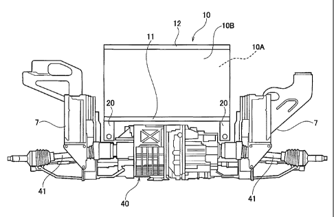
disclosure that there exists a need for an improved fuel cell electric
vehicle. This
invention addresses this need in the art as well as other needs, which will
become apparent
to those skilled in the art from this disclosure.
SUMMARY OF THE INVENTION
[0005] In the conventional fuel cell electric vehicle described in the above
mentioned
reference, a large space is required for installing a plurality of fluid
supply/discharge pipes
for supplying and discharging fuel cell fluids (such as fuel gas, oxidizing
gas, etc.) used in
the fuel cell stack in order to connect the fluid supply/discharge pipes to an
upper side and
a lower side of the fuel cell stack. Therefore, due to this space requirement
for the fluid
supply/discharge pipes, the number of the unit fuel cells stacked together to
form the fuel
cell stack cannot be greatly increased.
[0006] The present invention is contrived in light of the abovementioned
problem.
Thus, it is an object of the present invention to provide a fuel cell electric
vehicle that can
-1-
CA 02624687 2010-03-18
increase output power of the fuel cell by increasing the number of unit fuel
cells stacked
together to form a fuel cell stack.
[00071 In order to achieve the above mentioned object, a fuel cell electric
vehicle is
provided that basically comprises a driving motor, a fuel cell and first and
second
supply/discharge manifolds. The driving motor is disposed between a pair of
wheels. The
fuel cell is disposed above the driving motor having a plurality of unit cells
stacked in a
vertical direction of a vehicle. The fuel cell includes a plurality of through-
manifolds
configured and arranged to distribute a fuel gas, an oxidizing gas and a
coolant to the unit
cells. The first and second supply/discharge manifolds is disposed adjacent to
first and
second lateral end portions of the driving motor, respectively, with respect
to a lateral
direction of the vehicle The first and second supply/discharge manifolds are
fluidly
coupled to the through-manifolds to transport the fuel gas, the oxidizing gas
and the .
coolant relative to the fuel cell. The supply/discharge manifolds includes a
plurality of
fluid connection ports for transporting the fuel gas, the oxidizing gas and
the coolant at
positions that substantially overlap with positions of the through-manifolds
formed in the
fuel cell in a top plan view of the vehicle.
According to an embodiment of the present invention, there is provided a fuel
cell electric vehicle comprising:
a driving motor disposed between a pair of wheels, the driving motor having a
center
top surface and first and second lateral end top surfaces with the center top
surface
being positioned vertically higher than the first and second lateral end top
surfaces;
a fuel cell disposed above the driving motor having a plurality of unit cells
stacked in
a vertical direction of a vehicle, the fuel cell including a plurality of
through-manifolds
configured and arranged to distribute a fuel gas, an oxidizing gas and a
coolant to the
unit cells; and
first and second supply/discharge manifolds disposed adjacent to the first and
second
lateral end top surfaces of the driving motor, respectively, with bottom edges
of the
first and second supply/discharge manifolds being disposed vertically lower
than the
center top surface of the driving motor with respect to a lateral direction of
the vehicle,
and the first and second supply/discharge manifolds being fluidly coupled to
the
through-manifolds to transport the fuel gas, the oxidizing gas and the coolant
relative to
the fuel cell, the first and second supply/discharge manifolds including a
plurality of
fluid connection ports for transporting the fuel gas, the oxidizing gas and
the coolant at
positions that substantially overlap with positions of the through-manifolds
formed in
the fuel cell in a top plan view of the vehicle.
According to another embodiment of the present invention, there is provided a
fuel cell electric vehicle, comprising:
-2-
CA 02624687 2010-03-18
power outputting means for driving a pair of wheels;
fuel cell means including a plurality of through-manifolds that distributes a
fuel gas,
an oxidizing gas and a coolant to unit cells of the fuel cell means; and
fluid supplying/discharging means including a plurality of fluid connection
ports
fluidly coupled to the through-manifolds for transporting the fuel gas, the
oxidizing gas
and the coolant to or from the fuel cell means from lateral end portions of a
lower part
of the fuel cell means so that the fuel gas, the oxidizing gas and the coolant
supplied
from the fluid supplying/discharging means to the fuel cell means and
discharged from
the fuel cell means to the fluid supplying/discharging means flow in a
substantially
vertical direction with respect to a vehicle without the fuel gas, the
oxidizing gas and
the coolant passing through a center portion between the lower part of the
electricity
generating means and an upper part of the power outputting means with respect
to a
lateral direction of the vehicle.
[0008] These and other objects, features, aspects and advantages of the
present
invention will become apparent to those skilled in the art from the following
detailed
description, which, taken in conjunction with the annexed drawings, discloses
preferred
embodiments of the present invention.
BRIEF DESCRIPTION OF THE DRAWINGS
[0009] Referring now to the attached drawings which form a part of this
original
disclosure:
[0010] Figure 1 is a left side schematic elevational view showing an
arrangement of a
power system of a fuel cell electric vehicle in accordance with a first
embodiment of the.
present invention;
[0011] Figure 2 is a rear side perspective view of an area of the fuel cell
electric
vehicle where a fuel cell is disposed illustrating a state in which a fuel
cell housing is
removed in accordance with the first embodiment of the present invention;
-2a-
CA 02624687 2008-03-31
WO 2007/049127 PCT/IB2006/002986
[0012] Figure 3 is a rear elevational view of the area of the fuel cell
electric vehicle
where the fuel cell is disposed illustrating a state in which the fuel cell
housing is removed
in accordance with the first embodiment of the present invention;
[0013] Figure 4 is a top plan view of the area of the fuel cell electric
vehicle where the
fuel cell is disposed illustrating a state in which the fuel cell housing is
removed in
accordance with the first embodiment of the present invention;
[0014] Figure 5 is an exploded front perspective view illustrating an
attachment
structure between the fuel cell and a pair of supply/discharge manifolds in
accordance with
the first embodiment of the present invention;
[0015] Figure 6 is a series of diagrams (a) to (g) illustrating a structure of
the
supply/discharge manifold in accordance with the first embodiment of the
present
invention, wherein the diagram (a) is a perspective view of the
supply/discharge manifold
as viewed from a first side thereof, the diagram (b) is a perspective view of
the
supply/discharge manifold as viewed from a second side thereof, the diagram
(c) is a cross
sectional view of the supply/discharge manifold as taken along a section line
6c-6c in the
diagram (a), the diagram (d) is a cross sectional view of the supply/discharge
manifold as
taken along a section line 6d-6d in the diagram (b), the diagram (e) is a
cross sectional
view of the supply/discharge manifold as taken along a section line 6e-6e in
the diagram
(a), the diagram (f) is a cross sectional view of the supply/discharge
manifold as taken
along a section line 6f-6f in the diagram (a), and the diagram (g) is a cross
sectional view
of the supply/discharge manifold as taken along a section line 6g-6g in the
diagram (a);
[0016] Figure 7 is a rear side perspective view of the area of the fuel cell
electric
vehicle where the fuel cell is disposed illustrating a state in which the fuel
cell is housed
inside the fuel cell housing that is fixedly coupled to a vehicle frame in
accordance with
the first embodiment of the present invention;
[0017] Figure 8 is rear side perspective view showing an attachment structure
of the
fuel cell and the supply/discharge manifolds to a vehicle frame in accordance
with a
second embodiment of the present invention; and
[0018] Figure 9 is a series of diagrams (a) to (e) illustrating a structure of
a
supply/discharge manifold in accordance with a third embodiment of the present
invention,
wherein the diagram (a) is a perspective view of the supply/discharge manifold
as viewed
-3-
CA 02624687 2008-03-31
WO 2007/049127 PCT/IB2006/002986
from a first side thereof, the diagram (b) is a perspective view of the
supply/discharge
manifold as viewed from a second side thereof, the diagram (c) is a cross
sectional view of
the supply/discharge manifold as taken along a section line 9c-9c in the
diagram (a), the
diagram (d) is a cross sectional view of the supply/discharge manifold as
taken along a
section line 9d-9d in the diagram (b), and the diagram (e) is a cross
sectional view of the
supply/discharge manifold as taken along a section line 9e-9e in the diagram
(a).
DETAILED DESCRIPTION OF THE PREFERRED EMBODIMENTS
[0019] Selected embodiments of the present invention will now be explained
with
reference to the drawings. It will be apparent to those skilled in the art
from this
disclosure that the following descriptions of the embodiments of the present
invention are
provided for illustration only and not for the purpose of limiting the
invention as defined
by the appended claims and their equivalents.
[0020] Referring initially to Figures 1 to 7, a fuel cell electric vehicle 1
is illustrated in
accordance with a first embodiment of the present invention. Figure 1 is a
left side
schematic elevational view showing an arrangement of a power system of the
vehicle 1 in
accordance with the first embodiment. As shown in Figure 1, the vehicle 1
includes,
among other things, a passenger compartment 2, a motor room or motor
compartment 3, a
trunk compartment 4, a pair of front wheels 5 (left and right front wheels)
and a pair of
rear wheels 6 (left and right rear wheels). The passenger compartment 2 is
disposed in a
generally center part of the vehicle 1 with respect to the longitudinal
direction of the
vehicle 1. The motor compartment 3 (also called an engine compartment, a front
mechanical compartment, or a front box) is disposed in the front part of the
vehicle 1. The
trunk compartment 4 is disposed in the rear part of the vehicle 1. As shown in
Figure 1,
the front wheels 5 are disposed under the motor compartment 3, and the rear
wheels 6 are
disposed in the rear part of the passenger compartment 2. The arrow FR in
Figure 1
indicates the front direction, which is the direction of travel of the vehicle
1.
[0021] As shown in Figure 1, a fuel cell 10 is mounted inside the motor
compartment
3 above a driving motor 40, which is disposed between the left and right front
wheels 5.
The fuel cell 10 is configured and arranged to generate electric power to
drive the driving
motor 40, thereby causing the front wheels 5 to rotate to move the vehicle 1.
The fuel cell
is housed inside a housing 300 (casing).
-4-
CA 02624687 2008-03-31
WO 2007/049127 PCT/IB2006/002986
[0022] Figure 2 is a rear side perspective view of an area inside the motor
compartment 3 where the fuel cell 10 is disposed. Figure 3 is a rear
elevational view of
the area inside the motor compartment 3 where the fuel cell 10 is disposed.
Figure 4 is a
top plan view of the area inside the motor compartment 3 where the fuel cell
10 is
disposed illustrating a state in which the fuel cell housing 300 is removed.
Figures 2 to 4
illustrates a state in which the fuel cell housing 300 is removed.
[0023] The fuel cell 10 is preferably a solid polymer electrolyte
(polyelectrolyte) type
fuel cell. As shown in Figure 2, the fuel cell 10 includes a pair of fuel cell
stacks IOA and
I OB, a lower end plate 11 and an upper end plate 12. The fuel cell stacks 10A
and l OB the
lower and upper end plates 11 and 12are coupled together to form an integral
fuel cell unit.
As shown in Figure 5, each of the fuel cell stacks 10A and l OB is formed by
stacking a
plurality of unit cells 15 (unit fuel cells). Each of the unit cells 15
includes a membrane-
electrode assembly constructed from an electrolyte membrane including an ion
exchange
membrane, a fuel electrode disposed on one surface of the electrolyte
membrane, and an
air electrode disposed on the other surface of the electrolyte membrane. A
separator,
which forms channels used to supply fuel gas and oxidizing gas to the fuel
electrode and
the air electrode, respectively, is installed in the membrane-electrode
assembly to form the
unit cell 15.
[0024] In the vehicle 1, as shown in Figure 2, the two fuel cell stacks 1 OA
and 10B are
aligned and combined in the longitudinal direction of the vehicle 1 to form
the fuel cell 10
that has an integrated structure. As mentioned above, the fuel cell 10 is
positioned inside
the motor compartment 3 and mounted above the driving motor 40. In each of the
fuel
cell stacks 10A and 1 OB, the unit cells 15 are stacked in the vertical
direction of the
vehicle 1. In a top plan view, the unit cells 15 in each of the fuel cell
stacks 10A and l OB
have an elongated rectangular shape that is longer in the lateral direction of
the vehicle 1
and shorter in the longitudinal direction of the vehicle 1. Furthermore, the
unit cells 15
having the rectangular shape are arranged so that the fuel cell fluids (fuel
gas, oxidizing
gas, and coolant) flow in the unit cells 15 from one side of the vehicle 1 to
the other side
with respect to the lateral direction of the vehicle 1. As used herein, the
"fuel cell fluids"
includes the fuel gas, the oxidizing gas and the coolant that are supplied to
the fuel cell 10.
-5-
CA 02624687 2008-03-31
WO 2007/049127 PCT/IB2006/002986
[0025] Furthermore, as seen in Figure 3, the fuel cell 10 has a pair of
supply/discharge
manifolds 20 (first and second supply/discharge manifolds). The
supply/discharge
manifolds 20 are installed as a supply/discharge manifold section on the left
and right ends
of the lower portions of the fuel cell stacks IOA and I OB (both lateral lower
end portions
of the fuel cell stacks 10A and 10B with respect to the lateral direction of
the vehicle 1)
for distributing and collecting (converging) the fuel cell fluids (the fuel
gas, the oxidizing
gas, and the coolant) with respect to the fuel cell stacks 10A and 10B. More
specifically,
the distribution of the fuel cell fluids into the fuel cell stacks 10A and l
OB is carried out
by one of the supply/discharge manifolds 20 disposed on one side of the fuel
cell 10, and
the collecting of the fuel cell fluids from the fuel cell stacks 1 OA and 10B
is carried out by
the other one of the supply/discharge manifolds 20 disposed on the other side
of the fuel
cell 10.
[0026] Figure 5 is an exploded front perspective view of the fuel cell 10
including the
fuel cell stacks 10A and l OB and the supply/discharge manifolds 20. As shown
in Figure
5, each of the fuel cell stacks 1 OA and l OB includes a pair of through-
manifolds 101, a
pair of through-manifolds 102 and a pair of through-manifolds 103 formed in
both lateral
sides thereof, respectively. The through-manifolds 101, 102 and 103 are
configured and
arranged to supply or discharge the fuel gas, the oxidizing gas, and the
coolant to and from
the unit cells 15 of each of the fuel cell stacks 10A and 10B. Generally, the
through-
manifolds 101, 102 and 103 are formed by forming holes in each of the unit
cells 15 at
positions corresponding to the through-manifolds 101, 102 and 103 for
distributing the
fuel gas, the oxidizing gas, and the coolant to the interior part of each of
the unit cells 15,
and then stacking the unit cells 15 so that these holes are aligned to fluidly
communicate
with each other.
[0027] As seen in Figure 5, as mentioned above, each of the fuel cell stacks 1
OA and
I OB includes the through-manifolds 101, 102 and 103 that are formed on both
lateral ends
of the corresponding one of the fuel cell stacks l OA and I OB. More
specifically, the
through-manifolds 103 is used for the coolant water, the through-manifolds 102
is used for
the oxidizing gas, and the through-manifolds 101 is used for the fuel gas. The
through-
manifolds 103, 102 and 101 are formed in that order from the front in the fuel
cell stack
IOA disposed on the front side in the direction of travel of the vehicle 1.
Furthermore, the
-6-
CA 02624687 2008-03-31
WO 2007/049127 PCT/IB2006/002986
through-manifolds 103, 102 and 101 are formed in that order from the rear in
the fuel cell
stack 10B disposed on the rear side in the direction of travel of the vehicle
1. In other
words, in the fuel cell stack 10A on the front side and the fuel cell stack l
OB on the rear
side, the order of arrangement of the through-manifolds 101, 102 and 103 are
reversed, so
that the through-manifolds 103 used for the coolant is positioned on the
outermost end
(front or rear end) of the fuel cell 10, the through-manifolds 101 for the
fuel gas is
positioned on the innermost end, and the through-manifolds 102 for the
oxidizing gas is
positioned in an intermediate position between the through-manifolds 103 and
the
through-manifolds 101.
[0028] As mentioned above, each of the fuel cell stacks 10A and l OB has two
of the
through-manifolds 101 used for the fuel gas, two of the through-manifolds 102
used for
the oxidizing gas, and two of the through-manifolds 103 used for the coolant
that are
disposed on the left and right side of the respective fuel cell stack 10A or l
OB,
respectively. One of the through-manifolds 101, 102 and 103 is disposed on one
side of
the fuel cell stacks 10A and 10B to function as supply manifolds and the other
one of the
through-manifolds 101, 102 and 103 is disposed on the other side of the fuel
cell stack
I OA and l OB to function as discharge manifolds.
[0029] More specifically, the fuel gas is introduced to one of the
supply/discharge
manifolds 20 attached to a first lateral end portion of the fuel cell 10 via a
fuel gas pipe 21
(Figure 2) coupled to the supply/discharge manifold 20 attached to the first
lateral end
portion of the fuel cell 10. Then, the fuel gas is supplied and distributed
inside the fuel
cell stacks 10A and 10B (i.e., to each of the unit cells 15 constituting the
fuel cell stacks
I OA and 10B) via the through-manifolds 101 formed in a first lateral side of
the fuel cell
stacks I OA and l OB. The fuel gas supplied to the fuel cell 10 contributes to
the power
generating reaction in each of the unit cells 15 of the fuel cell stacks I OA
and I OB. Then,
after the fuel gas is used in the power generating reaction, the fuel gas
flows into the other
one of the supply/discharge manifolds 20 attached to a second lateral end
portion of the
fuel cell 10 via the through-manifolds 101 formed in a second lateral side of
the fuel cell
stacks 10A and l OB. Therefore, the fuel gas used in the fuel cell stacks 10A
and l OB are
collected together by the supply/discharge manifold 20 attached to the second
lateral end
portion of the fuel cell 10, and discharged to the outside via a fuel gas pipe
21 coupled to
-7-
CA 02624687 2008-03-31
WO 2007/049127 PCT/IB2006/002986
the supply/discharge manifold 20 attached to the second lateral end portion of
the fuel cell
10.
[0030] Likewise, the oxidizing gas is introduced to one of the
supply/discharge
manifolds 20 attached to a first lateral end portion of the fuel cell 10 via
an oxidizing gas
pipe (not shown) coupled to the supply/discharge manifold 20 attached to the
first lateral
end portion of the fuel cell 10. Then, the oxidizing gas is supplied and
distributed inside
the fuel cell stacks 1OA and 10B (i.e., to each of the unit cells 15
constituting the fuel cell
stacks 10A and 10B) via the through-manifolds 102 formed in a first lateral
side of the
fuel cell stacks 10A and 10B. The oxidizing gas supplied to the fuel cell 10
contributes to
the power generating reaction in each of the unit cells 15 of the fuel cell
stacks IOA and
I OB. Then, after the oxidizing gas is used in the power generating reaction,
the oxidizing
gas flows into the other one of the supply/discharge manifolds 20 attached to
a second
lateral end portion of the fuel cell 10 via the through-manifolds 102 formed
in a second
lateral side of the fuel cell stacks 10A and l OB. Therefore, the oxidizing
gas used in the
fuel cell stacks 1 OA and 10B are collected together by the supply/discharge
manifold 20
attached to the second lateral end portion of the fuel cell 10, and discharged
to the outside
via a oxidizing gas pipe (not shown) coupled to the supply/discharge manifold
20 attached
to the second lateral end portion of the fuel cell 10.
[0031] Likewise, the coolant is introduced to one of the supply/discharge
manifolds 20
attached to a first lateral end portion of the fuel cell 10 via a coolant pipe
coupled to the
supply/discharge manifold 20 attached to the first lateral end portion of the
fuel cell 10.
Then, the coolant is supplied and distributed inside the fuel cell stacks 10A
and 10B (i.e.,
to each of the unit cells 15 constituting the fuel cell stacks 10A and l OB)
via the through-
manifolds 103 formed in a first lateral side of the fuel cell stacks IOA and
10B. The
coolant supplied to the fuel cell 10 contributes to adjust temperature of the
fuel cell 10.
Then, after adjusting the temperature of the fuel cell 10, the coolant flows
into the other
one of the supply/discharge manifolds 20 attached to a second lateral end
portion of the
fuel cell 10 via the through-manifolds 103 formed in a second lateral side of
the fuel cell
stacks 10A and l OB. Therefore, the coolant used in the fuel cell stacks 10A
and l OB are
collected together by the supply/discharge manifold 20 attached to the second
lateral end
-8-
CA 02624687 2008-03-31
WO 2007/049127 PCT/IB2006/002986
portion of the fuel cell 10, and discharged to the outside via a coolant pipe
coupled to the
supply/discharge manifold 20 attached to the second lateral end portion of the
fuel cell 10.
[0032] With respect to the fuel cell stacks 10A and l OB that are aligned in
the
longitudinal direction, each of the through-manifolds 101, 102 and 103 of the
fuel cell
stack 1 OA and each of the through-manifolds 101, 102 and 103 of the fuel cell
stack l OB,
which are disposed on the same lateral side of the fuel cell 10 and which are
used for the
same fuel cell fluid (the fuel gas, the oxidizing gas or the coolant) perform
the same
function of supplying or discharging the fuel cell fluid. In other words, for
example, in a
case where the through-manifold 101 on the left side of the fuel cell stack
10A is used for
supplying the fuel gas to the fuel cell stack 10A and the through-manifold 101
on the right
side is used for discharging the fuel gas from the fuel cell stack I OA, the
through-manifold
101 formed on the left side of the fuel cell stack 10B is similarly used for
supplying the
fuel gas to the fuel cell stack l OB and the through-manifold 101 on the right
side of the
fuel cell stack l OB is used for discharging the fuel gas from the fuel cell
stack 10B. The
same is also true for the other through-manifolds 102 and 103 formed in the
fuel cell
stacks 10A and 10B.
[0033] However, the flow direction of each of the fuel cell fluids can be
changed
among the different fuel cell fluids (the fuel gas, the oxidizing gas or the
coolant). In other
words, the arrangements of the supply and discharge functions of the through-
manifolds
101, 102 and 103 (i.e., the flow direction of the fuel cell fluids in the fuel
cell stacks 10A
and l OB) can be determined independently of each other (the fuel gas, the
oxidizing gas or
the coolant). For example, the through-manifolds 102 that are disposed on the
left side of
the fuel cell stacks 1 OA and 10B can be used for discharging the oxidizing
gas from the
fuel cell stacks 10A and 10B, while the through-manifolds 101 that are
disposed on the
same left side of the fuel cell stacks 10A and 10B are used for supplying the
fuel gas to the
fuel cell stacks 1 OA and I OB. In such case, the flow direction of the fuel
gas inside the
fuel cell stacks 1 OA and I OB is opposite from the flow direction of the
oxidizing gas
inside the fuel cell stacks 10A and l OB. It is preferable to arrange the
through-manifolds
101 and 102 so that the flow direction of the fuel gas is opposite from the
flow direction of
the oxidizing gas.
-9-
CA 02624687 2008-03-31
WO 2007/049127 PCT/IB2006/002986
[0034] As the fuel gas and the oxidizing gas are supplied to the unit cells 15
of the fuel
cell stacks 1 OA and 10B, a reaction in which hydrogen is converted into
hydrogen ions
and electrons (H2 2H+ + 2e) occurs on the fuel electrode side in each of the
unit cells
15, and a reaction in which water is produced by oxygen, the hydrogen ions
that pass
through the electrolyte membrane, and electrons that are supplied via an
external circuit
(2H+ + 2e + (1/2)02 -> H2O) occurs on the fuel electrode side of each of the
unit cells 15.
The fuel cell 10 is formed by connecting in series a plurality (in this case,
one pair) of such
fuel cell stacks 10A and 10B, and each of the fuel cell stacks 10A and 10B
includes the
unit cells 15, in which such reactions occur, stacked together. Therefore, the
fuel cell 10
can generate several hundred volts of electric power.
[0035] Next, referring back to Figures 1 and 2, the power system of the
vehicle 1 using
the fuel cell 10 as a power source will be described.
[0036] As shown in Figures 1 and 2, the power system of the vehicle 1
preferably
includes a power plant (not indicated by any particular reference numeral)
having the fuel
cell 10 and auxiliary devices, a fuel gas storage tank 65, a power control
device (not
shown), the front wheel driving motor 40 and/or a rear wheel driving motor
(not shown), a
system controller (not shown), an electric power storage device (not shown)
and a low-
voltage and a high-voltage electrical cables. As mentioned above, the fuel
cell 10 is
configured and arranged to generate electric power by a reaction between the
fuel gas and
the oxidizing gas. The auxiliary devices of the power plant are actuated
during the
generation of power by the fuel cell 10. The fuel gas storage tank 65 stores
the fuel gas.
The power control device is configured to control the power generated by the
fuel cell 10,
and to adjust the supply of power to the respective parts of the vehicle 1.
The driving
motor 40 is coupled to the front wheels 5, and is configured and arranged to
drive the front
wheels 5 using the power generated by the fuel cell 10 and adjusted by the
power control
device. The system controller is configured to monitor the operating
conditions of the
vehicle 1 and the fuel cell 10, and to send control signals to the auxiliary
devices and other
devices. The electric power storage device is configured and arranged to
accumulate or
store the electric power if necessary. The low-voltage and high-voltage lines
are used for
the operation of the various types of auxiliary devices of the vehicle 1.
Furthermore, a
-10-
CA 02624687 2008-03-31
WO 2007/049127 PCT/IB2006/002986
high-power system component 60 (power control device) is mounted under the
floor of the
passenger compartment 2 of the vehicle 1 as shown in Figure 1.
[0037] In this embodiment of the present invention, the abovementioned
auxiliary
devices of the power plant preferably include a fuel gas supply device 31
(hydrogen
system part), an oxidizing gas supply device 32 (air system part), a
temperature adjustment
device (a radiator 50, etc.), and the like as shown in Figure 1.
[0038] The fuel gas supply device 31 is configured and arranged to adjust the
pressure,
temperature, flow rate, and the like of the fuel gas (mainly hydrogen, but may
also be a
modified gas such as methanol or the like, or some other modified gas), and to
supply the
fuel gas to the fuel cell 10. For example, the fuel gas supply device 31
includes a mass
flow meter configured and arranged to adjust the pressure, temperature, and
flow rate of
the fuel gas, and/or a fuel gas supply pump.
[0039] The oxidizing gas supply device 32 is configured and arranged to adjust
the
pressure, temperature, flow rate, and the like of the oxidizing gas (mainly
air), and to
supply the oxidizing gas to the fuel cell 10. For example, the oxidizing gas
supply device
32 includes a mass flow meter which is configured and arranged to adjust the
pressure and
flow rate of the oxidizing gas, a dust collector which is configured and
arranged to remove
foreign matter from the oxidizing gas, an air compressor configured and
arranged to
pressurize the oxidizing gas, a humidifier configured and arranged to adjust
the humidity
of the oxidizing gas, and/or a diluter configured and arranged to dilute the
oxidizing gas
after the gas has passed through the fuel cell.
[0040] The temperature adjustment device (such as the radiator 50) is
configured and
arranged to adjust the temperature of the fuel cell 10 to an appropriate
operating
temperature. For example, the temperature adjustment device includes a coolant
circulating pump configured and arranged to supply the coolant to the fuel
cell 10, a heat
exchange cycle device configured and arranged to dissipate the heat generated
by the fuel
cell 10 via a heat exchanger (e.g., the coolant), a heater configured and
arranged to heat
the fuel cell 10 by electrically generated heat or combustion heat when the
temperature of
the fuel cell 10 is low, and the like. In this illustrated embodiment, the
radiator 50 is
provided as the temperature adjustment device.
-11-
CA 02624687 2008-03-31
WO 2007/049127 PCT/IB2006/002986
[0041] During the operation of the vehicle 1, the reaction gases (the fuel gas
and the
oxidizing gas) are supplied to the fuel cell 10 from the fuel gas supply
device 31 and
oxidizing gas supply device 32, respectively, based on an opening degree of an
accelerator
of the vehicle 1. The power (electricity) generated in the fuel cell 10 is
transmitted
through a power blocking device (not shown), and is adjusted to the power
required for the
respective parts of the vehicle 1 by the power control device. The power is
then supplied
to the front wheel driving motor 40. The torque of the driving motor 40 is
transmitted to a
drive shaft 41 to rotate the drive wheels 5 of the vehicle 1.
[0042] As mentioned above, the system controller (not shown) is configured to
monitor the operating conditions of the vehicle 1 and the operating conditions
of the fuel
cell 10, and to send control signals to the auxiliary devices and other
devices of the vehicle
1. Therefore, the system controller is configured to control the respective
devices of the
vehicle 1 to the appropriate operating conditions.
[0043] In the first embodiment of the present invention, as shown in Figures 1
and 7,
the two fuel cell stacks 10A and 10B in which a plurality of the unit cells 15
are stacked in
the vertical direction of the vehicle 1 are accommodated in the housing 300.
The
supply/discharge manifolds 20 are disposed on the left and right ends of the
lowermost
surface in the stacking direction (vertical direction of the vehicle 1) of the
fuel cell 10
housed inside the housing 300. As shown in Figure 3, the supply/discharge
manifolds 20
are respectively disposed on the left and right side of the upper portion of
the driving
motor 40. More specifically, the supply/discharge manifolds 20 are
respectively installed
in a pair of open spaces formed above the left and right end portions of the
drive shaft 41
coupled to the driving motor 40.
[0044] Since the open spaces formed above the left and right end portions of
the drive
shaft 41 are extremely small, these open spaces are unsuitable for mounting
the auxiliary
devices of the fuel cell system that requires a large space. However, these
open spaces are
optimal for installing the supply/discharge manifolds 20, which are relatively
small
components. By installing the supply/discharge manifolds 20 in these open
spaces, it is
possible to set the vertical positions of lower ends of the supply/discharge
manifolds 20
below the upper end of the driving motor 40 as shown in Figure 3.
-12-
CA 02624687 2008-03-31
WO 2007/049127 PCT/IB2006/002986
[0045] In cases where the fluid supply/discharge parts are disposed entirely
on the
undersurfaces of the fuel cell stacks as in the conventional fuel cell
electric vehicle, the
fluid supply/discharge parts must be installed in positions above the upper
end of the
driving motor. Therefore, the size of the fuel cell positioned above the fluid
supply/discharge parts cannot be increased, which makes it impossible to
increase the
number of stacked unit cells in the fuel cell stacks in the conventional fuel
cell electric
vehicle. On the other hand, in the first embodiment of the present invention,
the number
of the unit cells 15 stacked together to form each of the fuel cell stacks 10A
and l OB can
be freely increased regardless of the height of the supply/discharge manifolds
20 by
disposing the supply/discharge manifolds 20 in the open spaces formed above
the left and
right end portions of the drive shaft 41. Accordingly, the output of the fuel
cell 10 can be
increased by increasing the number of the unit cells 15 stacked together to
form each of
the fuel cell stacks I OA and 10B.
[0046] For example, when the thickness (height) of each of the fluid
supply/discharge
manifolds 20 is set at several tens of millimeters and when the fluid
supply/discharge part
of the conventional fuel cell electric vehicle 1 is, for example, 50
millimeters, the number
of the unit cells 15 stacked together to form the fuel cell stacks 10A and l
OB can be
increased by the height of the fluid supply/discharge part of the conventional
fuel cell
electric vehicle 1. In other words, when the thickness of each of the unit
cells 15 is 2
millimeters, the number of the unit cells 15 can be increased by a maximum of
25 unit
cells. In such case, output of the fuel cell 10 can be increased by
approximately 10%.
[0047] As shown in Figure 3, since the supply/discharge manifolds 20 are
disposed
adjacent to both lateral end portions (left and right end portions) of the
upper part of the
driving motor 40, the length of the oblong shape (extending in the lateral
direction of the
vehicle 1) of the unit cells 15 in the fuel cell stacks 10A and l OB can be
extended so that
the unit cells 15 reach structural members of the vehicle 1 such as a pair of
side frame
members 7 of the vehicle frame. Accordingly, the area of each of the unit
cells 15 in
which the fuel gas and the oxidizing gas react can also be sufficiently
increased, so that the
current generated by each of the unit cells 15 can be increased as well.
[0048] Since the supply/discharge manifolds 20 are disposed on the lowermost
portions of the fuel cell stacks IOA and l OB, the water produced by the
chemical reaction
-13-
CA 02624687 2008-03-31
WO 2007/049127 PCT/IB2006/002986
of the fuel cell 10 can be quickly discharged to the supply/discharge
manifolds 20 from the
fuel cell stacks 10A and l OB by the force of gravity. Therefore, the fuel
cell 10 is less
likely to have inadequate power generating performance due to flooding (a
phenomenon in
which the gas diffusion layer is prevented from functioning by water, and
thus, the
chemical reaction tends not to proceed or is disrupted) and the like.
[0049] Since the supply/discharge manifolds 20 are disposed adjacent to both
lateral
end portions (left and right end portions) of the upper part of the driving
motor 40, the
height of the supply/discharge manifolds 20 can be increased without
interfering with the
large-diameter portion of the driving motor 40. Therefore, more water produced
by the
chemical reaction can be accumulated inside the supply/discharge manifolds 20,
the water
produced by the fuel cell stacks IOA and 10B can be discharged more easily,
and the fuel
cell 10 is less likely to have inadequate power generating performance due to
flooding (a
phenomenon in which the gas diffusion layer is prevented from functioning by
water, and
thus, the chemical reaction tends not to proceed or is disrupted) and the
like.
[0050] Furthermore, in this embodiment of the present invention, the area in
which the
supply/discharge manifolds 20 and the fuel cell stacks 10A and 10B are sealed
(i.e., the
area in which the supply/discharge manifolds 20 and the fuel cell stacks IOA
and I OB
contact each other via gaskets) can also be made extremely small. Therefore,
the sealing
properties of the overall connection surfaces between the supply/discharge
manifolds 20
and the fuel cell stacks l OA and 10B can be improved.
[0051] The supply/discharge manifolds 20 of the first embodiment are made
compact
because the supply/discharged manifolds 20 are spaced apart in the lateral
direction of the
vehicle 1. Therefore, the performance of the auxiliary devices of the fuel
cell 10 can be
improved by reducing the size and weight of the fuel cell system as a whole
and by further
expanding the spaces for other parts of the vehicle 1.
[0052] Next, the structure of the supply/discharge manifolds 20 and the fuel
cell stacks
10A and l OB will be described in further detail with reference to Figures 5
and 6.
[0053] As mentioned above, the fuel cell 10 includes the two fuel cell stacks
IOA and
10B formed by stacking the unit cells 15, a lower endplate 11 and an upper
endplate 12 as
shown in Figure 5. The lower endplate 11 is installed in common on lower
surfaces of the
fuel cell stacks 10A and 10B, and the upper endplate 12 is installed in common
on upper
-14-
CA 02624687 2008-03-31
WO 2007/049127 PCT/IB2006/002986
surfaces of the fuel cell stacks 10A and l OB. Although not shown in Figure 5,
the housing
300 (Figures 1 and 7) is provided to house the fuel cell 10, the lower
endplate and the
upper endplate 12 therein. The two fuel cell stacks 10A and l OB are aligned
in the
longitudinal direction of the vehicle 1 and mounted on the vehicle 1. As
described above,
the through-manifolds 101 for the fuel gas, the through-manifolds 102 for the
oxidizing
gas, and the through-manifolds 103 for the coolant are formed by holes or
openings
formed in each of the unit cells 15 that collectively form the fuel cell
stacks 10A and l OB.
[00541 As shown in Figure 5, the lower endplate 11 also includes a plurality
of
through-holes 111, 112 and 113 formed in positions that overlap with the
through-
manifolds 101, 102 and 103, respectively, of the fuel cell stacks 10A and l OB
in a top plan
view. Therefore, the through-holes 111, 112 and 113 of the lower endplate 11
fluidly
communicate with the through-manifolds 101, 102 and 103, respectively, of the
fuel cell
stacks lOA and lOB.
[00551 As described above, the supply/discharge manifolds 20, each of which
has a
solid-rectangular block-shape, are disposed on the lower parts of the left and
right end
portions of the fuel cell 10 in the lateral direction of the vehicle 1. The
supply/discharge
manifolds 20 are coupled to the undersurface of the fuel cell 10 (undersurface
of the lower
endplate 11) via a pair of gaskets 13 as shown in Figure 5.
[0056) Each of the supply/discharge manifolds 20 includes a fluid connection
port 201,
a pair of fluid connection ports 202 and a pair of fluid connection ports 203.
The fluid
connection port 201 is formed in a position that corresponds to the through-
manifolds 101
so that the fluid connection port 201 of the supply/discharge manifold 20 and
the through-
manifolds 101 are fluidly communicated with each other when the
supply/discharge
manifold 20 is coupled to the fuel cell 10 (via the lower endplate 11 and the
gasket 13).
The fluid connection ports 202 are formed in positions that correspond to the
through-
manifolds 102 so that the fluid connection ports 202 of the supply/discharge
manifold 20
and the through-manifolds 102 are fluidly communicated with each other when
the
supply/discharge manifold 20 is coupled to the fuel cell 10 (via the lower
endplate 11 and
the gasket 13). Likewise, the fluid connection ports 203 are formed in
positions that
correspond to the through-manifolds 103 so that the fluid connection ports 203
of the
supply/discharge manifold 20 and the through-manifolds 103 are fluidly
communicated
-15-
CA 02624687 2008-03-31
WO 2007/049127 PCT/IB2006/002986
with each other when the supply/discharge manifold 20 is coupled to the fuel
cell 10 (via
the lower endplate 11 and the gasket 13). Each of the gaskets 13 includes a
through-hole
131, a pair of through-holes 132 and a pair of through-holes 133 in positions
corresponding to the fluid connection ports 201, 202 and 203, respectively,
formed on the
upper end surface of the supply/discharge manifold 20.
[0057] The fluid connection port 201 of each of the supply/discharge manifolds
20 is
disposed in an innermost (central) position among the fluid connection ports
201, 202 and
203. The fluid connection port 201 of each of the supply/discharge manifolds
20 is a fluid
port used for the fuel gas, and formed as an elongated slot so that the fluid
connection port
201 is fluidly communicated with both of the through-manifolds 101 used for
the fuel gas
formed on one lateral side of the fuel cell stacks 10A and 10B. Furthermore,
the two
adjacent fluid connection ports 202 of each of the supply/discharge manifolds
20 are fluid
ports used for the oxidizing gas, and are formed so as to communicate with the
through-
manifolds 102 used for the oxidizing gas formed on one lateral side of the
fuel cell stacks
10A and l OB, respectively. Furthermore, the fluid connection ports 203
positioned
adjacent to the fluid connection ports 202 (disposed on the outermost side,
i.e., both
longitudinal ends of the supply/discharge manifolds 20 with respect to the
vehicle 1) are
fluid ports used for the coolant water, and are formed so as to communicate
with the
through-manifolds 103 used for the coolant water formed on one lateral side of
the fuel
cell stacks 1 OA and I OB, respectively.
[0058] In the first embodiment of the present invention, the fluid connection
ports 201,
202 and 203 of each of the supply/discharge manifolds 20 that cause the fuel
cell fluids to
flow through the fuel cell stacks 10A and l OB from the supply/discharge
manifolds 20,
and the through-manifolds 101, 102 and 103 formed through the fuel cell stacks
IOA and
10B in order to supply and discharge the fuel cell fluids to and from each of
the unit cells
15, are disposed in positions so that the fluid connection ports 201, 202 and
203 overlap
with the through-manifolds 101, 102 and 103 in a top plan view. As a result, a
region in
which the supply/discharge manifolds 20 and the fuel cell stacks 1 OA and l OB
are coupled
together can be reduced to allow reliable sealing of the through-manifolds
101, 102 and
103. In other words, the sealing region between the supply/discharge manifolds
20 and
the fuel cell 10 can be minimized. As a result, the probability of fuel gas
leakage due to
-16-
CA 02624687 2008-03-31
WO 2007/049127 PCT/IB2006/002986
defective sealing or the like can be reduced compared to cases where the
entire surfaces of
the fuel cell stacks are sealed as in the conventional fuel cell electric
vehicle.
[0059] As shown in Figure 6, the fluid connection port 201 of each of the
supply/discharge manifolds 20 used for the fuel gas fluidly communicates with
a
connection port 221 that is formed on a surface (e.g., a first side surface)
of the
supply/discharge manifold 20 other than the upper surface thereof via an
internal channel
211 (fluid channel). The fluid connection ports 202 of each of the
supply/discharge
manifolds 20 used for the oxidizing gas fluidly communicate with a connection
port 222
that is formed on a surface (e.g., a second side surface) of the
supply/discharge manifold
20 other than the upper surface thereof via an internal channel 212 (fluid
channel). The
fluid connection ports 203 of each of the supply/discharge manifolds 20 used
for the
coolant fluidly communicate with a connection port 223 that is formed on a
surface (e.g., a
third bottom surface) of the supply/discharge manifold 20 other than the upper
surface
thereof via an internal channel 213 (fluid channel). The connection ports 221,
222 and
223 are preferably formed in outside surfaces (the first, second and third
surfaces) of the
supply/discharge manifold 20 other than the upper end surface thereof.
[0060] The fluid communication relationships are indicated by the arrows A, B
and C
in Figure 6. On one lateral side of the fuel cell 10, the fuel gas A enters
into the
supply/discharge manifold 20 via the connection port 221, and leaves from the
fluid
connection port 201 via the internal channel 211 into the fuel cell stacks 10A
and 10B. On
the other lateral side of the fuel cell 10, the discharged fuel gas from the
fuel cell stacks
10A and 1 OB enters into the supply/discharge manifold 20 via the fluid
connection port
201, and leaves from the connection port 221 via the internal channel 211. On
one lateral
side of the fuel cell 10, the oxidizing gas B enters into the supply/discharge
manifold 20
via the connection port 222, and leaves from the fluid connection ports 202
via the internal
channel 212 into the fuel cell stacks 10A and 10B. On the other lateral side
of the fuel cell
10, the discharged oxidizing gas from the fuel cell stacks I OA and I OB
enters into the
supply/discharge manifold 20 via the fluid connection ports 202, and leaves
from the
connection port 222 via the internal channel 212. On one lateral side of the
fuel cell 10,
the coolant C enters into the supply/discharge manifold 20 via the connection
port 223,
and leaves from the fluid connection ports 203 via the internal channel 213
into the fuel
-17-
CA 02624687 2008-03-31
WO 2007/049127 PCT/IB2006/002986
cell stacks 1 OA and 10B. On the other lateral side of the fuel cell 10, the
discharged
coolant from the fuel cell stacks 1 OA and 1 OB enters into the
supply/discharge manifold
20 via the fluid connection ports 203, and leaves from the connection port 223
via the
internal channel 213.
[0061] The connection port 221 of each of the supply/discharge manifolds 20
used for
the fuel gas is formed in the inside surface of the supply/discharge manifolds
20 so that the
connection ports 221 for the fuel gas are disposed inside surfaces of the
supply/discharge
manifolds 20 disposed on the left or right end portions of the fuel cell 10.
As shown in
Figure 2, the fuel gas pipes 21 are connected, from the inside in the lateral
direction of the
vehicle 1, to the connection ports 221 (connected to the fuel gas channel
211), respectively,
of the supply/discharge manifolds 20. One of the fuel gas pipes 21 is used for
supplying
the fuel gas to the fuel cell 10, and the other one of the fuel gas pipes 21
is used for
discharging the fuel gas from the fuel cell 10. At least one of the fuel gas
pipes 21 that is
used for supplying the fuel gas to the fuel cell 10 is connected via the fuel
gas supply
device 31 to the fuel gas storage tank 65 mounted in the vehicle 1.
[0062] Each of the connection ports 222 used for the oxidizing gas is formed
in the
outside surface of the corresponding one of the respective supply/discharge
manifolds 20
with respect to the lateral direction of the vehicle 1, and a pair of
oxidizing gas pipes (not
shown) is connected, from the outside in the lateral direction of the vehicle
1, to the
oxidizing gas connection ports 222 (connected to the oxidizing gas channel
212) in the
supply/discharge manifolds 20, respectively. In this case as well, one of the
oxidizing gas
pipes is used for supplying the oxidizing gas to the fuel cell 10, and the
other one of the
oxidizing gas pipes is used for discharging the oxidizing gas from the fuel
cell 10. At least
one of the oxidizing gas pipes that is used for supplying the oxidizing gas to
the fuel cell
is connected to the oxidizing gas supply device 32.
[0063] Each of the connection ports 223 used for the coolant is formed in the
undersurface (bottom surface) of the corresponding one of the supply/discharge
manifolds
disposed on the left and right of the fuel cell 10. The connection ports 223
may be
formed on the front surface (facing in the direction of travel of the vehicle
1) of the
supply/discharge manifold 20 instead of the bottom surface thereof. A pair of
coolant
pipes 55 (one coolant pipe 55 shown in Figure 2) is connected to the coolant
water
-18-
CA 02624687 2008-03-31
WO 2007/049127 PCT/IB2006/002986
connection ports 223 of the supply/discharge manifolds 20, respectively. In
this case as
well, one of the coolant pipes 55 is used for supplying the coolant to the
fuel cell 10 and
the other one of the coolant pipes 55 is sued for discharging the coolant from
the fuel cell
10. The coolant pipes 55 are preferably connected to the radiator 50 that
serves as the
heating control device.
[0064] As a result of these piping connections, the fuel gas, the oxidizing
gas, and the
coolant are distributed to the fuel cell stacks 10A and l OB from the
supply/discharge
manifold 20 disposed on one of the left and right ends of the lower parts of
the fuel cell
stacks 10A and IOB through the through-manifolds 101, 102 and 103 of the fuel
cell
stacks 10A and l OB. Then, the fuel gas, the oxidizing gas, and the coolant
are distributed
to the respective unit cells 15 of the fuel cell stacks IOA and 10B, so that
electrical power
is generated by a reaction at the surfaces of the unit cells 15. Then, after
the generation of
electrical power in the fuel cell stacks 1 OA and 10B, the fuel gas, the
oxidizing gas, and
the coolant are collected and flow into the supply/discharge manifold 20 on
the opposite
side, and the fuel cell fluids are collected by the corresponding one of the
pipes coupled to
the supply/discharge manifold 20.
[0065] The left and right supply/discharge manifolds 20 have an identical
shape.
Therefore, the number of parts required is reduced and the assembly
characteristics of the
fuel cell system can be improved (e.g., the assembly time can be shortened).
[0066] It is preferable to directly couple the housing 300 of the fuel cell 10
with the
supply/discharge manifolds 20 by bolts or the like with the gaskets 13
sandwiched
therebetween without any other elastic members being interposed. The direction
of
attachment (e.g., direction of the bolt insertion) in this case may be from
the side of the
supply/discharge manifolds 20 or from the side of the housing 300 of the fuel
cell 10. By
directly connecting the fuel cell 10 and the supply/discharge manifolds 20,
the amount of
piping, hosing, or the like used to connect the fuel cell 10 and the
supply/discharge
manifolds 20 can be reduced. Accordingly, the number of parts required can be
reduced
and weight of the fuel cell system may be reduced too. Furthermore, even in
cases where
a physical object enters into the motor compartment 3 from the outside due to
a vehicle
collision or the like, the possibility of damaging the piping, hoses, or the
like can be
reduced.
-19-
CA 02624687 2008-03-31
WO 2007/049127 PCT/IB2006/002986
[0067] Since the housing 300 of the fuel cell 10 and the supply/discharge
manifolds 20
effectively formed as an integral rigid body, possibility of shifting of the
sealing parts
between the supply/discharge manifolds 20 and the fuel cell 10 can be reduced
in the case
of a vehicle collision or the like.
[0068] Figure 7 is a rear side perspective view of the area inside the motor
compartment 3 where the fuel cell 10 is disposed illustrating a state in which
the fuel cell
housing 300 is coupled to the fuel cell 10 and illustrating an attachment
structure between
the housing 300 and the side frame members 7 of the vehicle 1 in accordance
with the first
embodiment. In the example shown in Figure 7, a single rigid body in which the
supply/discharge manifolds 20 are directly connected to the housing 300 of the
fuel cell 10
is fastened to the side frame members 7 of the vehicle frame via a pair of
mounting
brackets 71. The mounting brackets 71 are preferably attached in advance to
the housing
300 of the fuel cell 10, and each of the mounting brackets 71 is tightened on
the
corresponding one of the side frame members 7 by a pair of bolts 72.
Therefore, the fuel
cell 10 and the housing 300 are supported by the vehicle body frame. In this
case, since
the dimension of the fuel cell 10 in the longitudinal direction (dimension in
the lateral
direction of the vehicle 1) can be extended to the vicinity of the side frame
members 7
because of the relationship in which the supply/discharge manifolds 20 are
disposed on
both lateral ends of the upper portion of the driving motor 40, there is no
loss of space for
installing peripheral parts by attaching the fuel cell 10 to the side frame
members 7.
[0069] Since the housing 300 of the fuel cell 10 extends as a bridge between
the left
and right side frame members 7, the housing 300 of the fuel cell 10 plays a
role equivalent
to that of a cross member of the vehicle body frame. Accordingly, especially
in the case
of a vehicle side collision, it is possible to securely prevent damage to the
fuel cell 10 or
the supply/discharge manifolds 20 due to the entry of the side frame members 7
or
external physical objects into the motor compartment 3.
[0070] In the present invention, the fuel gas supply components other than the
fuel gas
pipes 21 and the fuel gas storage tank 65 may be disposed in any position
inside the motor
compartment 3. However, considering the connection characteristics of the rear
fuel gas
storage tank 65 and the fuel gas pipes 21, it is desirable that the fuel gas
supply
-20-
CA 02624687 2008-03-31
WO 2007/049127 PCT/IB2006/002986
components be disposed rearwardly of the fuel cell 10 or under the floor panel
of the
passenger compartment 2.
[0071] Accordingly, in the present invention, the fluid supply/discharge
manifolds 20
are disposed on the left and right end portions of the lowermost part of the
fuel cell 10 and
the left and right end portions of the upper side of the driving motor 40. In
other words,
the supply/discharge manifolds 20 are spaced apart on the left and right side
of the fuel
cell 10 and disposed in the open spaces formed in the left and right end
portions of the
upper side of the driving motor 40. Since the driving motor 40 has a larger
diameter
portion in the center in the axial direction (the lateral direction of the
vehicle 1), and a
diameter of the driving motor 40 decreases toward the lateral end portions,
the open spaces
are formed on the upper side of the left and right end portions of the drive
shaft 41.
Accordingly, at least part of the undersurface of the fuel cell 10 can be
utilized as a
stacking space for the unit cells 15, thereby making it possible to increase
the number of
unit cells 15 that are stacked to form the fuel cell stacks 1 OA and 1 OB.
Therefore, the
output of the fuel cell 10 can be increased by increasing the number of
stacked unit cells
15.
SECOND EMBODIMENT
[0072] Referring now to Figure 8, a fuel cell electric vehicle in accordance
with a
second embodiment will now be explained. In view of the similarity between the
first and
second embodiments, the parts of the second embodiment that are identical to
the parts of
the first embodiment will be given the same reference numerals as the parts of
the first
embodiment. Moreover, the descriptions of the parts of the second embodiment
that are
identical to the parts of the first embodiment may be omitted for the sake of
brevity.
[0073] Figure 8 is rear side perspective view showing an attachment structure
of the
fuel cell 10 housed inside the housing 300 and the supply/discharge manifolds
20 to the
side frame members 7 in accordance with a second embodiment of the present
invention.
In the second embodiment, the supply/discharge manifolds 20 that are directly
connected
to the housing 300 of the fuel cell 10 are fastened to the side frame members
7 of the
vehicle frame via a pair of mounting brackets 75. In this respect, the second
embodiment
differs from the first embodiment, in which the housing 300 of the fuel cell
10 is directly
fastened to the side frame members 7 as shown in Figure 7. The fuel cell 10
can be
-21-
CA 02624687 2008-03-31
WO 2007/049127 PCT/IB2006/002986
supported by fastening the supply/discharge manifolds 20 to the side frame
members 7.
Although, in the illustrated embodiment, the supply/discharge manifolds 20 are
fastened to
the side frame members 7 via the mounting brackets 75, it would also be
possible to fasten
the supply/discharge manifolds 20 directly to the side frame members 7 without
interposing such mounting brackets 75. Except for the attachment structure
between the
fuel cell 10 and the side frame members 7, the second embodiment has exactly
the same
construction as the first embodiment. Accordingly, the same effects as those
of the first
embodiment can be obtained in the second embodiment of the present invention.
THIRD EMBODIMENT
[0074] Referring now to Figure 9, a fuel cell electric vehicle in accordance
with a third
embodiment will now be explained. In view of the similarity between the first
and third
embodiments, the parts of the third embodiment that are identical to the parts
of the first
embodiment will be given the same reference numerals as the parts of the first
embodiment. Moreover, the descriptions of the parts of the third embodiment
that are
identical to the parts of the first embodiment may be omitted for the sake of
brevity. The
parts of the third embodiment that differ from the parts of the first
embodiment will be
indicated with a single prime (').
[0075] Figure 9 is a series of diagrams (a) to (e) illustrating a structure of
a
supply/discharge manifold 20' in accordance with a third embodiment of the
present
invention, wherein the diagram (a) is a perspective view of the
supply/discharge manifold
20' as viewed from a first side thereof, the diagram (b) is a perspective view
of the
supply/discharge manifold 20' as viewed from a second side thereof, the
diagram (c) is a
cross sectional view of the supply/discharge manifold 20' as taken along a
section line 9c-
9c in the diagram (a), the diagram (d) is a cross sectional view of the
supply/discharge
manifold 20' as taken along a section line 9d-9d in the diagram (b), and the
diagram (e) is
a cross sectional view of the supply/discharge manifold 20' as taken along a
section line
9e-9e in the diagram (a).
[0076] The third embodiment of the present invention is identical to the first
embodiment except that the supply/discharge manifolds 20' are used in the
third
embodiment instead of the supply/discharge manifolds 20. More specifically,
each of the
supply/discharge manifolds 20' of the third embodiment is constructed as a
split structure
-22-
CA 02624687 2008-03-31
WO 2007/049127 PCT/IB2006/002986
formed by combining two members. In other words, two members are coupled
together at
a joint surface 250 as shown in the diagrams (a) and (b) of Figure 9 to form
the
supply/discharge manifold 20'. When the supply/discharge manifolds 20' is
constructed by
coupling two members as in the third embodiment, right-angle bending of
internal
channels 212' and 213' can be abolished, unlike in the first embodiment shown
in Figure 6.
Accordingly, in cases where the fuel cell fluids (the fuel gas, the oxidizing
gas and the
coolant) are supplied to the fuel cell stacks 1 OA and 1 OB, the pressure loss
of the fuel cell
fluids can be reduced. Therefore, the power generation performance of the fuel
cell 10
may be improved.
[0077] Although in Figures 6 and 9, the supply/discharge manifolds 20 and 20'
are
illustrated as being made of metal material, it is preferable from the
standpoint of securing
strength of the supply/discharge manifolds 20 or 20' to use resins, especially
reinforced
plastics, as the material for the supply/discharge manifolds 20 or 20' than to
use metals.
On the other hand, in cases where a metal material is used for the
supply/discharge
manifolds 20 or 20', it is preferable to apply a non-conductive material
coating on the
coolant channel (the internal channels 213 and 213'), where it is desired to
maintain the
insulation resistance. In case where the supply/discharge manifolds 20 or 20'
are made of
metal material, it is easy to maintain the strength when the supply/discharge
manifolds 20
or 20' are fastened to the vehicle body side frame members 7, as in the
example shown in
Figure 8.
[0078] In the first through third embodiments described above, the fluid
connection
ports 201, 202 and 203 of the supply/discharge manifolds 20 are arranged in
positions that
overlap with the through-manifolds 101, 102 and 103, respectively, formed in
the fuel cell
stacks 1 OA and 1 OB in a top plan view. Therefore, the cross-sectional area
of each of the
fluid supply/discharge manifolds 20 can be reduced to a range that allows
sealing of the
through-manifolds 101, 102 and 103 of the unit cells 15. Accordingly, the
sealing range
of the supply/discharge manifolds 20 and the fuel cell 10 can be minimized,
and thus,
defective sealing can be reduced. Moreover, since the size of the
supply/discharge
manifolds 20 can be minimized, the size and weight of the fuel cell system as
a whole can
be further reduced. In addition, the fuel cell fluids discharged from the fuel
cell stacks
1 OA and 1 OB can be conveyed to the supply/discharge manifolds 20 over a
minimal
-23 -
CA 02624687 2008-03-31
WO 2007/049127 PCT/IB2006/002986
distance. Therefore, the water produced inside the fuel cell stacks 10A and l
OB can be
quickly discharged into the supply/discharge manifolds 20 by the force of
gravity, so that
defective power generation caused by flooding can be prevented.
[0079] In the first through third embodiments described above, the coolant
channel
213 (connected to the coolant connection ports 203) are disposed in the outer
most
positions than the fuel gas channel 211 (connected to the fuel gas connection
ports 201),
the oxidizing gas channel 212 (connected to the oxidizing gas connection ports
202).
Therefore, insulation of the fuel cell 10 from the outside parts is possible
by maintaining a
sufficient insulation distance inside the supply/discharge manifolds 20 even
in cases where
the coolant circulates through the fuel cell stacks IOA and I OB that generate
a high voltage
of several hundred volts.
[0080] Specifically, since the fuel cell 10 generates a high voltage, it is
necessary to
prevent the transmission of a high voltage via the coolant in cases where the
coolant
passing through the internal parts deteriorates. Accordingly, in the first
through third
embodiments described above, the fluid channel 213 (connected to the fluid
connection
ports 203) through which the coolant from the outlet side of the fuel cell
stacks 1 OA and
l OB flows are disposed on the outermost sides in the supply/discharge
manifolds 20. As a
result, the insulation resistance can be maintained inside the
supply/discharge manifolds
20.
[0081] Moreover, the distance between the radiator 50 disposed on the front
end of the
vehicle 1 and the coolant channel 213 (connected to the coolant connection
ports 203) can
also be shortened so that a reduction in weight can be achieved by shortening
the coolant
pipes 55 or hoses from the radiator 50 to the coolant ports 203 of the
supply/discharge
manifolds 20. In other words, as shown in Figure 2, it is necessary to remove
the heat
absorbed inside the fuel cell 10 while the coolant, which has passed through
the fuel cell
10, passes through the radiator 50 at the front of the vehicle 1. In this
case, the piping and
hoses disposed between the radiator 50 and the supply/discharge manifolds 20)
can be
improved by placing the coolant channel 213 (connected to the fluid connection
ports 203)
on the outermost side of the supply/discharge manifolds 20, and the distance
of the coolant
pipe 55 and hoses that connect the radiator 50 and the coolant channel 213
(connected to
the fluid connection ports 203) of the supply/discharge manifolds 20 can be
minimized.
-24-
CA 02624687 2008-03-31
WO 2007/049127 PCT/IB2006/002986
Accordingly, the weight of the vehicle 1 may be reduced and the productivity
of the fuel
cell system may be improved.
[0082] In the present invention, the temperature adjustment device other than
the
coolant pipe 55 can also be disposed inside the motor compartment 3. However,
considering the connection characteristics of the radiator 50 and the coolant
pipe 55, it is
preferably to dispose the temperature adjustment device in front of the front-
wheel driving
motor 40.
[0083] In the first through third embodiments described above, the fluid
connection
port 201 (connected to the fuel gas channel 211) used for the fuel gas is
disposed at the
innermost position comparing to the fluid connection ports 202 used for the
oxidizing gas
and the fluid connection ports 203 used for the coolant. Therefore, the
distance between
the fuel gas channel 211 (connected to the fluid connection ports 201) and
invading
objects can be maximized even in cases where physical objects enter from the
outside in a
front end collision of the vehicle or the like. Accordingly, damage of the
supply/discharge
manifolds 20 can be securely prevented.
[0084] In other words, as a result of the fluid connection ports 201 being
disposed in
the innermost position of the supply/discharge manifold 20, the possibility of
invading
objects from the outside entering the fluid connection ports 201 can be
greatly reduced
even in cases where invading objects from the outside interfere with the
supply/discharge
manifolds 20.
[0085] In the first through third embodiments described above, the fuel gas
pipe 21
that leads the fuel gas from the fuel gas storage tank 65 to the fuel gas
channel 211
(connected to the fuel gas connection ports 221) is connected, from the inside
in the lateral
direction of the vehicle, to the connection ports 221 formed on the inside
surfaces of the
supply/discharge manifolds 20. Accordingly, even in cases where physical
objects enter
the vehicle 1 from the outside due to a vehicle side collision or the like,
the distance
between the invading objects and the fuel gas pipes 21 can be kept at a
maximum distance.
Therefore, damage of the fuel gas pipes 21 can be securely prevented.
[0086] In other words, since the fuel gas pipes 21 are generally thinner than
other
pipes used for the oxidizing gas and the coolant, connection between the fuel
gas pipes 21
and the supply/discharge manifolds 20 can be accomplished in the narrow spaces
between
-25-
CA 02624687 2008-03-31
WO 2007/049127 PCT/IB2006/002986
the supply/discharge manifolds 20 and the upper portion of the driving motor
40.
Accordingly, even in cases where invading objects enter the vehicle 1 from the
outside
during a vehicle side collision or the like, the possibility of damage of the
fuel gas pipes
21 can be greatly reduced.
[0087] In the first through third embodiments described above, the
supply/discharge
manifolds 20 are directly coupled to the housing 300 in which the fuel cell 10
is mounted
via the gaskets 13. Accordingly, the housing 300 of the fuel cell 10 and the
supply/discharge manifolds 20 can effectively form a single rigid body, so
that the fuel
leakage caused by shifting or the like of the sealing parts between the
supply/discharge
manifolds 20 and the housing 300 of the fuel cell 10 during a vehicle
collision or the like
can be prevented. Since the housing 300 is directly coupled to the
supply/discharge
manifolds 20 via the gaskets 13, the fuel cell fluids discharged from the fuel
cell stacks
1 OA and 1 OB can flow to the supply/discharge manifolds 20 over the shortest
distance.
Therefore, water produced inside the fuel cell stacks I OA and 1 OB can be
quickly
discharged into the supply/discharge manifolds 20 by the force of gravity.
Accordingly,
defective power generation of the fuel cell 10 due to flooding can be
prevented.
Furthermore, since the size of the supply/discharge manifolds 20 can be
minimized, the
size and weight of the fuel cell system as a whole can be further reduced.
[0088] In the first through third embodiments described above, the
supply/discharge
manifolds 20 or the housing of the fuel cell 10 can be fastened to the side
frame members
7 of the vehicle body frame, and the supply/discharge manifolds 20 and the
housing 300 of
the fuel cell 10 can be connected to the side frame members 7 of the vehicle
body frame as
a single rigid body. Therefore, damage of the fuel cell 10 or the
supply/discharge
manifolds 20 due to the entry of the side frame members 7 toward the motor
compartment
3 can be securely prevented even during a vehicle side collision or the like.
[0089] In the first through third embodiments, the fuel cell 10 includes one
pair of the
fuel cell stacks 1 OA and 1 OB. However, the number of the fuel cell stacks 1
OA and 1 OB is
not limited to two, and any number of the fuel cell stacks 1 OA and l OB can
be used to
form the fuel cell 10 to carry out the present invention.
GENERAL INTERPRETATION OF TERMS
-26-
CA 02624687 2008-03-31
WO 2007/049127 PCT/IB2006/002986
[0090] In understanding the scope of the present invention, the term
"comprising" and
its derivatives, as used herein, are intended to be open ended terms that
specify the
presence of the stated features, elements, components, groups, integers,
and/or steps, but
do not exclude the presence of other unstated features, elements, components,
groups,
integers and/or steps. The foregoing also applies to words having similar
meanings such
as the terms, "including", "having" and their derivatives. Also, the terms
"part," "section,"
"portion," "member" or "element" when used in the singular can have the dual
meaning of
a single part or a plurality of parts. Also as used herein to describe the
above
embodiments, the following directional terms "forward, rearward, above,
downward,
vertical, horizontal, below and transverse" as well as any other similar
directional terms
refer to those directions of a vehicle equipped with the present invention.
Accordingly,
these terms, as utilized to describe the present invention should be
interpreted relative to a
vehicle equipped with the present invention. The terms of degree such as
"substantially",
"about" and "approximately" as used herein mean a reasonable amount of
deviation of the
modified term such that the end result is not significantly changed.
[0091] While only selected embodiments have been chosen to illustrate the
present
invention, it will be apparent to those skilled in the art from this
disclosure that various
changes and modifications can be made herein without departing from the scope
of the
invention as defined in the appended claims. For example, the size, shape,
location or
orientation of the various components can be changed as needed and/or desired.
Components that are shown directly connected or contacting each other can have
intermediate structures disposed between them. The functions of one element
can be
performed by two, and vice versa. The structures and functions of one
embodiment can be
adopted in another embodiment. It is not necessary for all advantages to be
present in a
particular embodiment at the same time. Every feature which is unique from the
prior art,
alone or in combination with other features, also should be considered a
separate
description of further inventions by the applicant, including the structural
and/or
functional concepts embodied by such feature(s). Thus, the foregoing
descriptions of the
embodiments according to the present invention are provided for illustration
only, and not
for the purpose of limiting the invention as defined by the appended claims
and their
equivalents.
-27-