Note: Descriptions are shown in the official language in which they were submitted.
CA 02624744 2008-03-31
FILLING SYSTEM FOR POTENTIALLY HAZARDOUS MATERIALS
FIELD
[0001] The present invention relates to systems, devices, and methods for
filling capsules and
other types of containers with radioactive and/or other types of potentially
hazardous materials.
BACKGROUND
[0002] A number of scientific uses require relatively small aliquots of
radioactive materials.
For example, nuclear medicine employs solutions of radioisotopes, such as
Technetium-99m,
Iodine-123, Iodine-125, Iodine-131, Phosphorous-32, Indium-111, Cobalt-57, and
Chromium-51,
as radiopharmaceuticals or as radioactive tracers. These radioisotopes
typically are measured
and dispensed for use. However, for safety reasons, it is highly desirable
that the technician
responsible for measuring and dispensing radioisotopes be exposed to minimal
radioactivity. It
is also desirable in some instances that the actual radioisotope doses be
empirically determined in
terms of radioactivity.
-1-
CA 02624744 2008-03-31
[0003] Thus, techniques for dispensing small volumes of radioactive materials
are needed.
SUMMARY
[00041 In one aspect, the present invention provides systems for filling
containers with
radioactive and/or other types of potentially hazardous materials. Preferred
systems are those
that deposit one or more radioactive materials in relatively small containers
such as capsules or
small vials. Such systems typically comprise a shielding material that
substantially defines a
chamber and, preferably, substantially blocks radioactivity, a conduit
extending through the
shielding material into the chamber, and a securing unit that is disposed in
the chamber proximal
to the conduit and is adapted to receive a container through the conduit. The
systems of the
present invention can further comprise filling devices, at least one solution
delivery device that is
disposed in the chamber and adapted to meter an aliquot from a radioactive
stock solution and
inject the aliquot into the container; at least one of a]ogic device that
controls the solution
delivery device, and/or a tapered guide lid that is positioned over the
radioactive stock solution:
[0005] The present invention also provides filling methods that involve, for
example, using the
conduit to place a first container in the securing unit, metering an aliquot
from a radioactive
stock solution, and injecting the aliquot into the container.
BRIEF DESCRIPTION OF THE DRAWINGS
[0006] The numerous objects and advantages of the present invention may be
better understood
by those skilled in the art by reference to the accompanying non-scale
figures, which are
provided by way of example and are not intended to limit the invention.
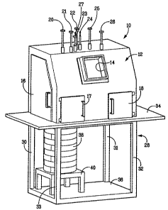
[0007] Fig. 1 is a perspective view of a container filling device.
[0008] Fig. 2 is another perspective view of the filling device with the
shield removed.
-~-
CA 02624744 2008-03-31
[0009] Fig. 3 is a sectional view of a securing unit and a conduit assembly
within the device.
[0010] Fig. 4 is a sectional view of a stock solution container and a needle
assembly.
100111 Fig. 5 is a sectional view of a securing unit and a needle assembly.
[0012] Fig. 6 is a sectional view of a securing unit and a container transfer
assembly.
[0013] Fig. 7 is a schematic of system including a container filling device.
DETAILED DESCRIPTION
[0014] The present invention provides systems for filling containers with
radioactive and/or
other types of potentially hazardous materials. Potentially hazardous
materials according to the
invention are those that present or are suspected to present one or more types
of health risks to a.
human who is exposed to the material. Representative materials according to
the invention
include chemicals and biological agents including but not limited to.poisons,
toxins, mutagens,
and teratogens. Materials of particular interest with respect to the present
invention are those
that emit one or more radioactive species.
[0015] Containers according to the invention are vessels that can contain or
substantially
contain a potentially hazardous material of interest. Vessels that contain the
material include
sufficient structure to surround it; vessels that substantially contain the
material bound it with
sufficient structure to restrict its movement in one or more directions.
Containers of particular
interest with respect to the present invention are those (such as capsules,
tubes, ampoules, and
vials) that are relatively small (i.e., have a volume less than about 10 mL,
more preferably less
than about I mL:
[00161 The systems of the invention include a shielding material that
substantially defmes a
chamber. Any of a wide variety of shield materials can be used that provide an
effective barrier
to the potentially hazardous material and are either capable of forming a
substantially closed
-3-
CA 02624744 2008-03-31
surface shape that substantially defines a chamber or being disposed upon a
substantially closed-
surface shape that substantially defines chamber. Thus, a shielding material
that substantially
defines a chamber need not do so alone. Representative shielding materials
include metals,
alloys, and/or polymers; shield materials of particular interest are those
(such as lead, tungsten,
and other suitable metals and alloys) that provide an effective barrier to
radioactive species.
Preferably, the shielding material is at least as effective as lead_ Chambers
according to the
invention can have virtually any shape, although substantially rectangular
chambers and
substantially cylindrical chambers are probably most common.
[0017] The systems of the invention include a conduit extending through the
shield material
into the chamber. Conduits according to the invention are substantially hollow
structures that
supply a pathway for introducing containers to the chamber. The conduit may be
made from any
suitable material such as, for example, lead, tungsten, and other metals and
allows that pr.ovide
an effective barrier to radioactive species. In cross-section, the conduit may
have any shape,
provided that the shape allows the container to pass through the conduit.
Preferably, the shape of
the conduit substantially corresponds to the shape of the container. In
certain embodiments of
the invention, conduits cari be interchangeable such that each is adapted for
use with specific
containers. Conduits according to the invention can optionally include a
device or other
structure that permits manipulation objects within the chamber. One such
representative device
is a tamping rod that engages and helps seal the container.
[0018] The systems of the invention also include a securing unit that is
disposed in the
chamber proximal to the conduit and is adapted to receive a container through
the conduit.
Securing units according to the invention generally are capable of receiving
at least one container
and, preferably, more than one container. The portion of the securing unit
that receives the
container preferably has a shape that corresponds to the shape of the
container. In embodiments
-4-
CA 02624744 2008-03-31
in which the securing unit receives more than one container, the securing unit
can be capable of
being indexed, that is, of moving each container sequentially past a given
work area. Indexing is
useful for allowing the securing unit to receive further containers, to allow
the containers to be
filled, and/or to move the containers to an area where they may be removed
from the securing
unit. Preferably, the securing unit is a carousel,,but all shapes that allow
indexing, for example, a
rectangle with an array of ports, are contemplated.
[0019] Fig. 1 shows one representative filling system 10 according to the
invention having a
shield material 12 and a window 14 disposed therein for viewing the chamber.
The window 14
may be formed from any substantially transparent, radiation-shielding
material, such as leaded
glass, in any of the many known configurations. For example, the window 14 may
a single layer
of leaded glass or a plurality of layers having an inert gas or a shielding
oil disposed between
them.
[0020] The system shown in Fig.l also includes a plurality of doors 16-18 for
accessing the
..chamber. These doors may be constructed of any suitable shielding material,
and may corriprise
handles, hinges, locks, or other features typically found on doors. It is
understood that the
number of doors and windows may be varied within the spirit of the invention.
[0021] A plurality of rods 20-26 extend through shield 12 and into the chamber
that it defines.
At least one of the rods 20-26 is hollow, and thus can serve as a conduit
through which a
container can pass into the chamber. A removable tamper 27 can be disposed in
the conduit to
minimize or 'prevent radiation leakage and provide a structure that can be
used to move or
otherwise contact a container that has been placed in the chamber. In
embodiments in which
capsules are placed in the chamber, the rod can be used to tamp a cap upon the
capsule. At least
one of the rods 20-26 is rotatable to provide movement of components disposed
inside the
chamber, as will be described with regard to Fig. 2.
-5-
CA 02624744 2008-03-31
[0022] The system 10 is optionally placed on a table 28 or some other type of
support. Table
28 has a plurality of legs 30-33, a top 34, and a base 36. Although not
depicted, table 28 may
further comprise at least two wheels to provide mobility, preferably four
wheels.
[0023] In the particular embodiment shown in Fig. 1, an optional dose
calibrator 38 having a
stand 40 is a'ssociated with system 10. The dose calibrator 38 is provided
with the necessary
logic and components to measure the radioactivity of the dispensed materials
to confum dosage.
Dose calibrators are commercially available from Capintec Inc., Ramsey, New
Jersey, USA.
[0024] Turning now to Fig. 2, the chamber contains a securing unit 50 having a
plurality of
ports 52 to receive a plurality of containers 54. Although the securing unit
50 is depicted as a
carousel, those skilled in the art will appreciate that other designs are
contemplated.
[0025] In the embodiment depicted, the container 54 is a capsule, although all
type of
containers can be used. Suitable capsules are well known to those skilled in
radiopharmaceutical
preparations., and include those conmmercially available from Capsugel,
Greenwood, South
Carolina, USA. In this embodiment, containers 54 are intioduced to the ports
52 via a conduit
formed in the rod 23, as will be described with reference to Fig. 3. It is
understood that the
conduit has a sufficient diameter to allow the container to pass. In certain
embodiments of the
invention, the conduit is treated (as, for example, with a lubricant) to
reduce friction.
[0026] A locator 56 is provided in the chamber for placement of a stock
solution container 58
of radioactive materials to be dispensed. The stock solution container 58
preferably is made of
lead or tungsten. As will be further described with respect to Fig. 4, a guide
60 is attached to the
rod 26 and disposed proximal to the locator 56.
[0027] A solution delivery device 62 rotates around an axis substantially
defined by rod 25 and
is movable between a position proximal to the securing unit 50 and a position
proximal to the
stock solution container 58. The solution delivery device 62 is used to fill
container 54 with
-6-
CA 02624744 2008-03-31
stock solution. As'depicted, the solution delivery device 62 is a syringe.
Suitable syringes and
other types of devices for filling containers are well known to those skilled
in
radiopharmaceutical preparations, and include those commercially available
from Becton
Dickson, Franklin Lakes, New Jersey USA or Qosina, Edgewood, New York, USA. A
relatively.
long 22G needle is suitable for piercing a capsule such as described above. An
optional guide
(see structure 108 in Fig. 5) can be used to guide the needle of the solution
delivery device 62 to
container 54. 0
[00281 The solution delivery device 62 is associated with dispensing controls
to allow accurate
dispensing of the radioactive materials in selected volumes. Although doses
may be determined
in terms of radioactivity, it is helpful to accurately dispense certain
volumes of stock solution to
attain the desired radioactivity. In one embodiment, the volume of a dispensed
aliquot of stock
solution is about 1 L to about 10,000 L. Preferably, the volume of the
aliquot is about .1 L to
about 500 L, more preferably about 2 L to about 200 L. In one embodiment,
the volume of
the aliquot is less than about 1000 L: Those skilled in the art will
understand that term "filling"
as used herein includes placing any volume of solution in a container, and
does not require
placing therein a volume that that corresponds to the container's capacity.
100291 Metering of the aliquot can be effected through operation of a computer
control means.
Control means amenable to the practice of this invention include computing
devices such as
microprocessors, microcontrollers, capacitors, switches, circuits, logic
gates, or equivalent logic
devices. In one embodiment, the controls provide a plurality of volumes from
which to select.
Alternatively, the controls can provide for data entry to specify the volume
desired. The controls
may also be used to achieve a certain dosage. For example, if the
concentration of stock solution
is provided, the controls may calculate the volume required to attain a
certain radioactive dose.
Moreover, if a dosage of a certain radioactivity will be required for
administration later, for
-7-
CA 02624744 2008-03-31
example, two days later, the controls can account for the radioactive decay
rate by dispensing an
aliquot which has a radioactivity greater than the desired dosage by an amount
representing the
decay factors occurring over the time between dispensing and administration.
Those skilled in
'the art will readily appreciate these and other desirable features of the
controls based on the
foregoing, as well as how to obtain them, such as by programming.
[0030] For use in dispensing radiopharmaceuticals or other types of
potentially hazardous
material, the solution delivery device 62 may require rinsing or sterilizing.
A plurality of
optional holding containers 64-66 are provided for receiving the needle of the
solution delivery
device. These holding containers 64-66 may contain conventional rinse or
sterilization solutions.
In certain embodiments, the rinse solution is water or isopropyl alcohol.
[0031] A second locator 68 is provided in the chamber for indicating placement
of a shipping
container 70 for receiving a shipping vial 71. The shipping container 70
preferably is made of
lead, tungsten, alloys, or any material with a density greater than or equal
to lead, provided it
substantially blocks radioactivity. The shipping via171 is necessarily smaller
than the shipping
container and is the vessel in which the container(s) are actually placed. The
shipping vial
preferably is plastic. The shipping container 70 and the shipping vial 71 have
substantially
similar shapes at their interface. The shapes cooperate to prevent the
shipping via171 from
rotating when capped or uncapped. In one embodiment, the distal end of the rod
21 (not
depicted) is adapted to grasp the cap of the shipping vial. This rod 21
assembly can also lift the
shipping vial 71 for visual inspection.
[0032] A container transfer assembly 72 is attached to the rod 24 and includes
a receiver (118,
Fig. 6) that is adapted to engage a container and remove it from the securing
unit 50. The
transfer assembly 72 then places the container 54 in the shipping via171. In
one embodiment,
the transfer assembly 72 operates by creating a snug fit between receiver
(118, Fig. 6) and
-8-
CA 02624744 2008-03-31
container 54. The container may be released applying a force to the container
sufficient to
overcome the snug fit, as will be discussed with reference to Fig. 6.
100331 A vial transfer assembly 74 is attached to the rod 20 and includes a
receiver that is
adapted to engage the shipping vial 71 and remove it from the shipping
container 70. 'The vial
transfer assembly 74 then places the shipping vial 71 in the dose calibrator
38 (Fig. 1) via an
access port 76. The access port 76 can be brought closer to the dose
calibrator by an optional
actuator 78 such as a pneumatic cylinder with associated controls. The vial
transfer assembly 74
can be used to recapture the shipping vial 71 after the dose calibrator 38
(Fig. 1) determines, the
dosage and to place the shipping vial back in the shipping container 70.
100341 The capped shipping vial may receive an aluminum seal to indicate it
has been secured.
In certain embodiments, the aluminum seal is crimped on the capped shipping
vial. The capped
shipping vial may alternatively receive a screw cap or a snap cap to indicate
it has been secured.
(0035] Referring to Fig. 3, the securing unit 50 is rotatable around the axis
substantially
defined byrod 22, as depicted by double headed.arrow A, to allow the various
ports 52 to come
proximal to rod 23. Each port 52 may comprise a bore 80 and a port insert 82
disposed within
the bore. A variety of shapes are contemplated for the port inserts 82,
provided that the shapes
have complementary surfaces to accommodate the desired container. In
operation, a container,
such as a capsule, is passed down the conduit 84 of the rod 23 along an axis C
and received in
the port 52 proximal to the distal end of the rod. The securing unit 50 is
then indexed in either
direction indicated by arrow A, to bring an empty port 52 proximal to rod 23
to receive another
container. Alternatively, the securing unit could remain stationary and the
rod 23 could be
provided to move around the securing unit to allow indexing.
[0036] In certain embodiments, the rod 23 is lowered to the securing unit 50,
as depicted by
double headed arrow B, to dispose the container in the port 52. This allows
the container to be
-9-
CA 02624744 2008-03-31
properly aligned. Thus, in embodiments where the rod 23 can be lowered to the
securing unit 50,
the securing unit and the conduit are adapted to move with respect to each
other in a first plane
and a second plane.
[0037] A rod that is adapted to pass through the conduit.84 and engage the
container may be
provided. This rod may be used to tamp a cap on a filled capsule, for example.
[0038] Turning now to Fig. 4, the stock solution container 58 surrounds a vial
86 of a stock
solution such as, for example, Technetium-99m, Iodine-125, Iodine-
131,.Phosphorous-32,
Indium-l 11, Cobalt-57, and/or Chromium-51. Stock solution vials
conventionally are capped
with an aluminum layer 88 and a rubber septum 90.
[0039] A guide lid 92 according to certain embodiinents of the present
invention is adapted to
be placed on the stock solution container 58 to guide the solution delivery
device 62 to the stock
solution vial 86. The guide lid 92 may be formed from, for example, lead or
tungsten, and has a
generally tapered inner wall 94 that can direct objects placed therein to the
central portion of the
area.that the wall defines. Those skilled in the art will recognize that this
inner wall need.not
have the continuously sloping surface depicted in Fig. 4, but simply should
taper to the extent
necessary to direct objects placed therein to its central portion.
[0040] In certain embodiments, the guide 60, attached to the rod 26 via a
plate 96, is also
provided to guide the solution delivery device 62 to the stock solution vial
86. The guide 60 can
include a relatively thick 16G needle 98 suitable for piercing the aluminum
layer 88 and the
rubber septum 90 of the stock solution vial. The gauge of the needle 98 should
generally be
sufficiently large to allow a needle 100 of the solution delivery device 62 to
pass through it, thus
allowing the needle 100 to reach the stock solution to draw an aliquot as
described above.
[0041] Referring to Fig. 5, a filling guide 102 is provided comprising a rod
104, a plate 106
attached to the rod 104, and a tapered guide member 108 attached to the plate.
The solution
-10-
CA 02624744 2008-03-31
delivery device 62 typically retains an amount of stock solution 109. The
generally tapered
guide member 108 reinforces the needle 100 of the solution delivery device 62
to facilitate
piercing of the container 54 to deliver the aliquot and directs the needle to
the central portion of
the guide member. In certain embodiments, the plate 106 acts as a stop to
prevent the needle 100.
from protruding too far into container 54.
[0042] Turning to Fig. 6, container transfer assembly 72 is shown having a
first plate 110 and a
second plate 112 attached to the rod 24. A pin 114 is disposed between the
plates 110 and 112,
and is actuated by an actuator 116. The pin 114 is optional, as the transfer
assembly 72 could be
tapped against the shipping vial to remove the container or a pneumatic force
could be used in
place of the pin and actuator.
[00431 A flexible plastic apron 118 is disposed in the transfer assembly 72 to
engage a
container in a snug fit. The fit should be sufficient tight to allow the
container to, be lifted from
the port 52, but not so tight as to damage the container upon application of a
force required to
release it from the apron 118. The transfer assembly 72 engages the container,
removing it from
the securing unit 50;-and can be used to place the container in a shipping
vial 71.
[0044] In operation, a container is placed in the securing unit via the
conduit and an aliquot
from a radioactive stock solution is metered out and injected into the
container. The securing
unit may be indexed and another container injected with an aliquot from a
radioactive stock
solution. The radioactive stock solutions can be the same or different, and
the volumes of the
aliquots can be the same or different.
[0045] Referring to Fig. 7, a system is depicted comprising a filling'system
10, a logic device
120, a data entry device 122, and traces 124 for electrically connecting the
components are
provided. The filling system 10 is described above. The logic device 120 may
be the same or
different as the control means described above, and includes computing devices
such as
-11-
CA 02624744 2008-03-31
microprocessors, microcontrol]ers, capacitors, switches, circuits, logic
gates, or equivalent logic
devices. The data entry device 122 may be a keyboard, a notepad, a dial, or a
series of setting
switches.
(0046) Certain features are, for clarity, described herein in the context of
separate
embodiments, but may also be provided in combination in a single embodiment.
Conversely,
various features that are, for brevity, described in the context of a single
embodiment, may also
be provided separately or in ariy subcombination. Further, reference to values
stated in ranges
include each and every value within that range.
(0047) After reading the concepts that have been described with reference to
specific
embodiments, skilled artisans will appreciate that other aspects,
modifications, changes, and
embodiments are possible without departing from the scope of the invention as
set forth in the
claims below. Accordingly, the specification and figures are to be regarded in
an illustrative
rather than a restrictive sense, and all such modifications are intended to be
included within the
scope of invention.
(0048) Many aspects and embodiments have been described above and are merely
exemplary
and not limiting. Benefits, advantages, solutions to problems, and any feature
that may cause the
same to occur are not to be construed as a critical, required, or essential
feature of any or all the
claims.
- 12-