Note: Descriptions are shown in the official language in which they were submitted.
CA 02624813 2010-08-17
DEVICE AND METHOD FOR COOKING FOOD ON A GRILL
FIELD OF THE INVENTION
[0001] The present invention relates to a device and a method for cooking
food, and in particular meat, on a grill having opposed upper and lower
platens
wherein a gap spacing between the platens is adjusted in an initial stage and
one
or more subsequent stages of the cooking time for the food.
BACKGROUND
[0002] Numerous cooking devices are known in the art for cooking meat and
other food products. One such device is a clamshell griddle or grill disclosed
in
U.S. Patent Nos. 6,016,743, 5,910,207, 5,755,150, and 5,569,478.
These clamshell grills are typically used in quick service restaurants to cook
meat,
for example, one or more hamburger patties, efficiently in a short amount of
time
between heated upper and lower cooking surfaces having a fixed gap spacing
therebetween.
[0003] When cooking a plurality of meat items, conventional grills and methods
do not account for differences in the thickness of each meat item due to the
fixed
gap spacing between the upper and lower cooking surfaces. Therefore, known
grills and cooking methods may not uniformly cook the meat from item to item
if
there is any substantial variance in meat thickness from item to item.
1
CA 02624813 2008-04-03
WO 2007/044330 PCT/US2006/038618
[0004] Further, quick service restaurants may freeze their meat to maintain
the
freshness of the meat and to enable the meat to be used on an as-needed basis.
It is well known, however, that known grills and grill cooking methods often
sear
or burn the surface of the meat during cooking due to the initial compression
of
the meat and the substantial temperature difference between the frozen meat
and the heating surfaces. Further, due to the high temperature of the heating
surfaces and the cooking time required to thaw and thereafter cook frozen meat
thoroughly, known grills and cooking methods often cause the cooked meat to
lose tenderness and a substantial amount of internal moisture.
[0005] Accordingly, there is a need for an improved device and method for
cooking meat on a grill which improves the taste, texture, and mouthfeel of
the
cooked meat product and more uniformly cooks a plurality of food items, such
as
hamburger patties.
SUMMARY
[0006] In accordance with one aspect of the present invention, a method of
cooking food such as meat having an initial uncooked thickness on a grill is
provided. The method uses different compression levels determined by
predetermined gap spacings to thaw and sear the meat items and to maintain the
internal moisture and tenderness of the meat products. The method comprises:
causing the meat, which is typically frozen meat, to be located between two
opposed platens, the opposed platens each having opposed cooking surfaces,
and the opposed cooking surfaces defining a gap spacing that is adjustable;
2
CA 02624813 2008-04-03
WO 2007/044330 PCT/US2006/038618
adjusting the gap spacing between the platens so that during an initial stage
of
the cooking the gap spacing is less than the nominal initial uncooked
thickness of
the meat, and during a secondary stage of the cooking after the initial stage,
the
gap spacing between the platens is increased but is still less than the
nominal
initial uncooked thickness.
[0007] It will be appreciated that meat and other fresh, chilled and frozen
food
products will vary somewhat in thickness. Accordingly, the gap spacing is
adjusted based on the nominal thickness of the type of food product to be
cooked
and not for each individual food item. Thus, reference herein to an initial
thickness of the meat or other food product should be understood to refer to
the
nominal initial thickness of the type of food product to be cooked.
[0008] Typically, the meat product is a hamburger patty having a top and a
bottom, and the step of causing the meat to be located between two opposed
platens comprises orienting the hamburger patty so that the top and bottom of
the hamburger patty oppose the platen cooking surfaces. The orienting of the
hamburger patty as such is typically performed by closing one of the platens
onto
the opposed other of the platens in a clamshell-like fashion.
[0009] In accordance with another aspect of the present invention, the gap
spacing during an initial stage of the cooking is in the range of from about
75% to
about 90% of the initial thickness of the meat, and preferably is from about
83%
to about 86% of the initial thickness of the meat.
3
CA 02624813 2008-04-03
WO 2007/044330 PCT/US2006/038618
[0010] In accordance with another aspect of the present invention, during a
portion of the initial stage, the gap spacing is greater than the initial
thickness of
the meat.
[0011] In accordance with yet another aspect of the present invention, the gap
spacing during a secondary stage of the cooking is in the range of from about
87% to about 97% of the initial meat thickness, and preferably is from about
88%
to about 95% of the initial meat thickness.
[0012] In accordance with yet another aspect of the present invention, the gap
spacing is greater than the thickness of the meat during a portion of the
secondary stage.
[0013] In accordance with yet another aspect of the present invention, the
meat
product has a cooking time and the initial stage constitutes about 6% to about
13% of the cooking time and the second stage constitutes from about 87% to
about 94% of the cooking time for the meat product.
[0014] In accordance with still another aspect of the present invention, the
gap
spacing is adjusted by applying a force of about 0.20 to 0.35 pounds per
square
inch of meat to one or more of the platens. The applied force is sufficient to
substantially squeeze the meat and achieve a desired gap spacing during the
initial stage.
[0015] In accordance with another aspect of the present invention, a grill is
provided for cooking one or more meat products having an initial uncooked
thickness. The grill includes at least one set of opposed upper and lower
platens. Each of the opposed platens has a platen cooking surface mounted for
4
CA 02624813 2008-04-03
WO 2007/044330 PCT/US2006/038618
movement toward and away from the other of the opposed platens for defining
an adjustable gap spacing between the platen cooking surfaces. The grill
further
includes gap spacing adjustment means for controlling and changing the gap
spacing between the platen cooking surfaces during the grilling of a meat item
located between the platens so that during the grilling the gap spacing is
less
than the initial uncooked thickness of the meat, and during a secondary stage
of
the cooking, after the initial stage, the gap spacing between the platens is
increased but is still less than the initial uncooked thickness.
[0016] In accordance with yet another aspect of the present invention, gap
spacing adjustment means for controlling and adjusting the gap spacing between
the platen cooking surfaces comprises a drive mechanism associated with at
least one of the platens for moving the cooking surface of at least one of the
platens towards and away from the cooking surface of the other of the opposed
platens and to control and adjust the gap spacing between the cooking surfaces
of the two platens.
[0017] In accordance with still another aspect of the present invention, the
drive mechanism is capable of applying sufficient force to a plurality of
frozen
hamburger patties to reduce the thickness of the frozen hamburger patties by
at
least about 25% from the nominal initial thickness of the patties.
[001$] In accordance with yet another aspect of the present invention, the gap
spacing adjustment means for controlling and adjusting the gap spacing between
the platen cooking surfaces further comprises a microprocessor capable of
controlling the drive mechanism. The microprocessor may be programmed to
CA 02624813 2008-04-03
WO 2007/044330 PCT/US2006/038618
cause the drive mechanism to compress meat items located between the
cooking surfaces of the platens during an initial cooking stage to a gap
spacing
ranging from about 75% to about 90% of the initial thickness of the meat item,
and thereafter, during a secondary stage of the cooking, to increase the gap
spacing between the platens to a range of from about 87% to about 97% of the
initial thickness of the meat item.
[0019] In accordance with still another aspect of the present invention, the
microprocessor is programmed to cause the drive mechanism to retain an initial
stage gap spacing of about 75% to about 90% of the initial meat thickness for
about 6% to about 13% of the total cooking time for the meat item, and
thereafter
to retain a secondary stage gap spacing of about 87% to about 97% of the
initial
meat thickness for about 87% to about 94% of the total cooking time.
[0020] In accordance with yet another aspect of the present invention, a grill
is
provided comprising: upper and lower opposed platens, each platen having a
platen cooking surface mounted for movement towards and away from each
other for defining an adjustable gap spacing between the platen cooking
surfaces; and a drive mechanism associated with at least one of the platens
for
moving the cooking surface of at least one of the platens toward and away from
the cooking surface of the other platen to control and adjust the gap spacing
between the cooking surfaces of the two platens during; the grilling, of a
meat
product located between the platens so that during the grilling the gap
spacing is
less than the initial uncooked thickness of the meat, and during a secondary
6
CA 02624813 2008-04-03
WO 2007/044330 PCT/US2006/038618
stage of the cooking, after the initial stage, the gap spacing between the
platens
is increased but is less than the initial uncooked thickness.
[0021] In accordance with another aspect of the present invention, the grill
includes a microprocessor which is capable of controlling the drive mechanism.
The microprocessor may be programmed to cause the drive mechanism to
compress meat items located between the cooking surfaces of the platens during
an initial cooking stage to about 75% to about 90% of the initial meat
thickness,
and thereafter, during a secondary stage of the cooking, to obtain a gap
spacing
between the cooking surfaces of the two platens that is in the range of from
about 87% to about 97% of the initial thickness of the meat item.
[0022] In accordance with yet another aspect of the present invention, the
microprocessor is programmed to cause the drive mechanism to retain an initial
stage platen gap spacing of about 75% to about 90% of the initial meat
thickness
for about 6% to about 13% of the total cooking time, and thereafter to retain
a
secondary stage platen gap spacing of about 87% to about 97% of the initial
meat thickness for about 87% to about 94% of the total cooking time.
[0023] In accordance with yet another aspect of the invention, the method
includes more than two and preferably five stages. In at least one point in
time in
an initial thaw stage, the initial platen gap spacing is equal to the initial
uncooked
thickness of the meat. In at least one point in time in a second sear stage,
the
gap spacing is less than the initial uncooked thickness of the meat. In a
third-
moisture release stage, the gap spacing is again equal to the initial uncooked
7
CA 02624813 2008-04-03
WO 2007/044330 PCT/US2006/038618
thickness of the meat. In fourth and fifth cook stages, the gap spacing is
less
than the initial uncooked thickness of the meat.
[0024] In accordance with yet another aspect of the invention, in a five-stage
method, the drive mechanism provides an initial gap spacing equal to the
thickness of the meat for about 6% of the total cooking time during a first
stage, a
gap spacing of about 78% to 82% of the meat thickness for about 13% of the
total cooking time during a second stage, a gap spacing about equal to the
thickness of the meat for about 1 % of the total cooking time during a third
stage,
a gap thickness of about 88 to 92% of the meat thickness for about 40% of the
total cooking time during a fourth stage, and a gap spacing of about 91-93% of
the meat thickness for about 40% of the total cooking time during a fifth
stage.
[0025] Other advantages and features of the invention will become apparent
from the following description and from reference to the drawings.
BRIEF DESCRIPTION OF THE DRAWINGS
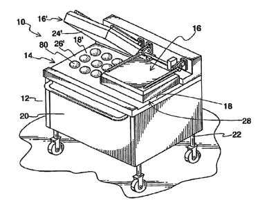
[0026] FIG. 1 is a perspective view of a cooking apparatus in accordance with
the present invention;
[0027] FIG. 2 is a side elevation view of the cooking apparatus of FIG.1;
[0028] FIG. 3 is a rear elevation view taken at line 3-3 of FIG. 2;
[0029] FIG. 4A is a fragmentary front elevation view of a hamburger patty
located between two opposed platens, wherein the gap spacing is greater than
the thickness of a hamburger patty;
[0030] FIG. 4B is a fragmentary front elevation view of the hamburger patty
located between opposed platens at a point in time in the initial stage of
cooking;
8
CA 02624813 2008-04-03
WO 2007/044330 PCT/US2006/038618
[0031] FIG. 4C is a fragmentary front elevation view of a hamburger patty
located between opposed platens at a point in time in the secondary stage of
cooking;
[0032] FIG. 5 is a flow diagram of a method of cooking meat items in
accordance with a two-stage embodiment of the present invention; and
[0033] FIG. 6 is a flow diagram of a method of cooking meat items in
accordance with a five-stage embodiment of the present invention.
DETAILED DESCRIPTION
[0034] While this invention is susceptible of embodiment in many different
forms, there is shown in the drawings and described in detail herein, several
specific embodiments with the understanding that the present disclosure is to
be
considered as exemplifications of the principles of the invention and is not
intended to limit the invention to the embodiments illustrated.
[0035] Referring to the drawings and in particular to FIG. 1, clamshell grill
10 is
shown as having a housing 12 and a griddle 14. Griddle 14 includes two spaced
apart upper platens 16, 16' and two opposed spaced-apart lower platens 18,
18'.
It is understood, however, that any number of opposed pairs of upper platens
and lower platens may be utilized. Housing 12 comprises a body portion 20
having four leg members 22 with fixed casters such that grill 10 can be
maintained in a stationary position in the kitchen of the restaurant in which
grill 10
is located for example. Typically, housing 12 is constructed from stainless
steel,
such as chrome molybdenum steel, but may be formed from any other suitable
material.
9
CA 02624813 2008-04-03
WO 2007/044330 PCT/US2006/038618
[0036] Each upper platen 16,16' includes an upper cooking surface 24,24' and
each lower platen 18,18' of grill 10 includes a lower cooking surface 26,26'.
When an opposed pair of platens are in a closed position 28, as shown by
platens 16,18 in FIG. 1, opposed pair of platens 16,18 define an adjustable
gap
spacing 30 within which a meat item or a plurality of meat items may be
cooked.
Gap spacing 30 determines the level of compression of the meat items disposed
therein. Platens 16,16',18,18' are typically formed from a heat-treated,
polished,
and "meat safe" material such as chrome molybdenum steel, but may be of any
other suitable material.
[0037] Inside housing 12, a lower platen heating member 32, which may be a
gas burner or an electric heater is arranged under lower platens 18,18' to
supply
heat thereto. Upper platens 16,16' typically include a body portion 34,34'
having
an electric heater (not shown) embedded within body portion 34,34'.
Preferably,
upper platens 16, 16' and the electric heater are of an aluminum casting
heater
type. Alternatively, any other suitable structure for providing heat to upper
platens 16,16' and lower platens 18,18' may be used.
[0038] To adjust and maintain predetermined gap spacing 30 of grill 10,
opposed upper and lower platens 16,16',18,18' are mounted for relative
movement toward and away from each other. In one embodiment, as shown in
FIG. 2,, housing 12 includes a drive mechanism 36 and a microprocessor (not
shown) to control drive mechanism 36. The microprocessor may be any suitable
system known in the art for controlling the movement of any components of
drive
mechanism 36. Drive mechanism 36 is associated with at least one of platens
CA 02624813 2008-04-03
WO 2007/044330 PCT/US2006/038618
16,18 for moving one cooking surface 24, 26 of one of platens 16,18 towards
and
away from a cooking surface 24,26 of the other one of platens 16,18 Drive
mechanism 36 thus controls and adjusts gap spacing 30 between the cooking
surfaces of the two platens.
[0039] The microprocessor controls the drive mechanism 36 and thus the
magnitude of gap spacing 30 throughout a predetermined cooking time for the
meat product(s) on grill 10. The predetermined time typically includes two or
more stages. In a two-stage embodiment of the invention, the predetermined
time includes an initial cooking stage and a secondary cooking stage. In at
least
one point in time in the initial stage, one or both of an opposed upper platen
16
and a lower platen 18 are moved with respect to one another by drive
mechanism 36 such that gap spacing 30 is less than the initial uncooked
thickness of meat 80. In at least one point in time in the secondary stage of
the
cooking, drive mechanism 36 increases the gap spacing 30 between upper
platen 16 and lower platen 18 to a gap spacing 30 which is greater than the
smallest gap spacing in the initial stage.
[0040] In one embodiment, the microprocessor may be programmed to cause
drive mechanism 36 to obtain a gap spacing 30 during the initial stage which
is
about 75% to about 90% of the initial meat thickness for about 6% to about 13%
of the total cooking time. Further, the microprocessor may be programmed to
cause drive mechanism 36 to obtain a gap spacing between the cooking
surfaces of the two platens during the secondary stage of the cooking that is
in
11
CA 02624813 2008-04-03
WO 2007/044330 1 PCT/US2006/038618
the range of from about 87% to about 97% of the initial thickness of the meat
item.
[0041] In a multi-stage embodiment of the invention, the predetermined time
includes more than two and preferably five stages. In at least one point in
time in
an initial thaw stage, gap spacing 30 is equal to the initial uncooked
thickness of
the meat 80. In at least one point in time in a second sear stage, gap spacing
30
is less than the initial uncooked thickness of meat 80. In a third moisture
release
stage, gap spacing 30 is again equal to the initial uncooked thickness of meat
80.
In fourth and fifth cook stages, the gap spacing 30 is less than the initial
uncooked thickness of meat 80.
[0042] In one multi-stage embodiment, the microprocessor may be
programmed to cause drive mechanism 36 to obtain a gap spacing 30 during the
various stages which is approximately the percentage of the initial meat
thickness shown in the following table, which also shows the approximate
percentages of total cooking time represented by each stage:
TABLE 1
Stage Sequence Description Compression Cooking Time
(Percentage of
Initial uncooked
thickness)
1 Thaw 0% 6%
2 Sear 78%-82% 13%
3 Moisture Release 0% 1 %
12
CA 02624813 2010-08-17
4 Cook 1 88%-92% 40%
Cook 2 91%-93% 40%
[0043] It is understood that drive mechanism 36 may create a predetermined
gap spacing between each set of opposed upper and lower platens. Thus, the
drive mechanism will operate until the opposed upper and lower platens have a
predetermined value which is typically entered into an input for the
microprocessor. In obtaining the predetermined gap spacing 30, drive
mechanism 36 must exert a sufficient amount of pressure to render the gap
spacing less than the thickness of the meat. In the present invention, drive
mechanism 36 is capable, for example, of applying a sufficient force to a
plurality
of frozen hamburger patties 80 to reduce the thickness of the frozen hamburger
patties by at least about 25% from their nominal initial thickness. It should
also
be understood that the pressure applied and the compression percentages
shown in Table 1 are neither exact nor constant, as they will vary depending
on
the actual thickness of individual patties or other food items. The figures
shown
in Table 1 are based on a nominal initial thickness for a particular type of
patty or
other food item.
[0044] In one embodiment, as shown in FIGS. 2-3 and described in U.S.
Patent No. 5,735,150, drive mechanism 36 comprises an arm portion 38 and a
bearing portion 40 which supports upper platen 16, a feed screw assembly 42,
and a motor with a brake 44, a pair of cam
13
CA 02624813 2011-08-09
rollers which are rotatably attached to a pair of cam roller supports 48 on a
corresponding position of arm portion 38, and a microprocessor (not shown).
[0045] Arm portion 38 comprises a shaft support portion 50 rotatably supported
by bearing portion 40, a platen support 52 for supporting upper platen 16, and
a
cam operation portion 54 attached to a first and a second end of arm portion
38
for respectively placing shaft support portion 50 therebetween. Arm portion 38
is
designed to rotate from a generally horizontal position, as-shown by platens
16,18 in FIG. 4A, to an open position 56 as shown by platens 16',18' in FIG.
2.
Additionally, bearing portion 40 and arm portion 38 are designed so as to not
be
rotated counterclockwise beyond closed position 28. After reaching the
generally
horizontal position, bearing portion 40 and arm portion 38 may move vertically
downward or upward as desired to adjust gap spacing 30 while maintaining
upper platen 16 parallel with lower platen 18.
[0046] Feed screw assembly 42 comprises a feed screw shaft 58 which
extends vertically through a feed screw nut support 60 and a lower frame 62
disposed on a lower rear portion 64 of housing 12. Feed screw shaft 58 is
designed so as to penetrate rotatably a feed screw support 65 attached to
lower
frame 62. Additionally, feed screw shaft 58 is adapted to be rotationally
driven
by motor 44, which is typically attached to lower frame 62. Additionally, feed
screw assembly 42 comprises a feed screw nut 66 which engages feed screw
shaft 58. Feed screw nut 66 is supported by feed screw nut support 60. Feed
screw nut support 60 moves with feed screw nut 66 as feed screw nut 66 travels
along feed screw shaft 58. Bearing portion support shafts 68 are installed
14
CA 02624813 2008-04-03
WO 2007/044330 PCT/US2006/038618
respectively on both sides of feed screw nut support 60. Each bearing support
shaft 68 is adapted to be moved vertically through a direct acting bearing 70
and
a second direct acting bearing 72 as the feed screw nut support 60 moves.
[0047] A corresponding bearing portion 40 is connected to an upper end 74 of
each bearing support shaft 68. As such, bearing portion 40 is moved up and
down as bearing support shaft 68 moves up and down. A rotary encoder 76 is
attached to the lower frame and is rotated by the revolution of motor 44 by a
belt
78. Rotary encoder 76 generates an electric pulse in proportion to its
rotation.
[0048] The microprocessor of grill 10 comprises a motor control circuit for
controlling the motion of the motor 44, a counter for receiving and computing
the
electric pulse from rotary encoder 76, and a comparator circuit. Also, the
microprocessor typically comprises a desired distance setting circuit for
setting
gap spacing 30 between upper platen 16 and lower platen 18. For example, in
operation, the user may input a desired gap spacing value which represents the
desired gap spacing 30 between an opposed upper platen 16 and lower platen
18 into the comparator circuit through the desired distance setting circuit by
operating a position switch arranged on a lower operation panel of the housing
12.
[0049] In operation, to open the griddle from closed' position 28 to an open
position 56, the user may actuate a raise switch of an upper operation panel
on
clamshell grill 10. Thereafter, a command for opening one platen, and
preferably
upper platen 16 with respect to lower platen 18, is inputted into the motor
control
circuit. The motor control circuit, in response, actuates motor 44 to revolve
in the
CA 02624813 2008-04-03
WO 2007/044330 1 PCT/US2006/038618
designated direction. As the motor 44 revolves, feed screw shaft 58 is rotated
in
the designated direction and feed screw nut 66 engages with feed screw shaft
58
and moves in the designated direction, as in for example an upper direction.
Consequently, feed screw nut support 60 and bearing portion support shafts 68
are also moved upward from a lower position.
[0050] As bearing portion support shafts 68 are moved upward, bearing
portions 40 are also moved upward such that arm portion 38, supported by
bearing portions 40, is also moved upward. Arm portion 38 thus holds and
supports upper platen 16 and maintains upper platen 16 in generally horizontal
position, relatively parallel to lower platen 18. While being moved upward,
cam
operation portion 54 of arm portion 38 begins to contact a corresponding cam
roller 46 arranged on the back portion of the housing 12. Because the position
of
the cam roller 46 is fixed, a pressing force is applied to the cam operation
portion
54 of arm portion 38 in a downward (clockwise) direction such that arm portion
38 is rotated clockwise around shaft portion 50, which is supported by bearing
portion 40.
[0051] When arm portion 38 is rotated, a number of electric pulses
proportional
to the number of revolutions of motor 44 are added to the counter by rotary
encoder 76. For example, an upper limit of the count value which corresponds
to
the travel of bearing portion 40 and upper platen 16 is set in the counter.
The
counter incrementally counts the electric pulses from rotary encoder 76. When
the counter reaches the upper limit of the count value set previously, a
command
for stopping the motor is issued to the motor control circuit to stop the
driving
16
CA 02624813 2008-04-03
WO 2007/044330 PCT/US2006/038618
motion of motor 44. As a result, upper platen 16 is automatically stopped and
held in the desired open position.
[0052] Thereafter, to move an opposed upper platen 16 and lower platen 18
into closed position 28, the user may input at least one desired gap spacing
30
suitable for the meat item or items to be cooked and the length of cooking
time at
the selected gap spacing into the microprocessor. Subsequently, any other gap
spacing 30 and stage period may be inputted, such as for example a secondary
stage of cooking as described herein.
[0053] To close upper platen 16 with respect to lower platen 18, a command is
communicated to the motor control circuit. The motor control circuit
rotatively
drives motor 44 in the reverse direction of that discussed above.
Consequently,
feed screw shaft 58 is rotated in the reverse direction of that discussed
above
and feed screw nut 66 which engages feed screw shaft 58 is moved downward
along feed screw shaft 58. As a result, bearing portion support shafts 68 also
are
moved downward from an upper position. As bearing portion support shafts 68
are moved downward, bearing portions 40 are also moved downward, and arm
portion 38 supported by bearing portions 40 begins to be rotated, along with a
corresponding upper platen 16 in a counterclockwise direction around shaft
support portion 50.
[0054]; The counterclockwise rotation of arm portion 38 is executed by the
self-
weight of upper platen 16 and is designed to be stopped at generally
horizontal
position where upper platen 16 is parallel to lower platen 18 with gap spacing
30
there between. When bearing portion support shafts 68 are moved down further
17
CA 02624813 2008-04-03
WO 2007/044330 PCT/US2006/038618
after the upper platen 16 becomes parallel to lower platen 18, upper platen 16
is
moved downward in the direction to reduce gap spacing 30 as desired while
maintaining upper platen 16 in parallel relation to lower platen 18.
Alternatively,
gap spacing 30 may be increased by moving upper platen 16 and lower platen
18 further apart from one another.
[0055] While bearing portion support shafts 68 are moved down, the number of
electric pulses proportional to the number of revolutions of the motor 44 is
added
to the counter by rotary encoder 76. The counter decrementally counts the
electric pulses from rotary encoder 76. In particular, the counter decreases
the
number of electric pulses generated by rotary encoder 76 from the upper limit
of
the count value set previously. The counter outputs the current count value to
the comparator circuit. The comparator circuit compares this count value with
the gap spacing value set by the operator. When both values become equal, a
motor stop command is issued to the motor control circuit to stop the driving
of
motor 44. Therefore, upper platen 16 is automatically stopped and held at the
desired gap spacing 30. Gap spacing 30 between upper platen 16 and lower
platen 18 at such time is equal to the desired value set by the operator.
[0056] A cook timer may specify a predetermined selectable cooking time for
the meat product. Once the cooking time has passed, upper platen 16 can be
automatically raised and rotated to be moved to open position 56, and the user
is
notified of the end of the cooking time by a buzzer alarm, or other suitable
audio
or visual alarm. Alternatively, the gap spacing can be further increased or
decreased as desired. When the operator is notified that the cooking is
finished,
18
CA 02624813 2008-04-03
WO 2007/044330 PCT/US2006/038618
the cooked meat product can be removed from griddle 14. The distance
between opposed upper platen 16 and lower platen 18 may be precisely and
automatically set to an arbitrary value, for example, between 5 mm and 20 mm
by selecting the appropriate relation between a screw pitch of the feed screw
shaft 58 and the number of electric pulses generated by the rotary encoder 76.
[0057] It is understood that in the grill and method of the present invention,
one
of platens 16,16', 18,18' may be movable while an opposed one of platens
16,16',18,18' remains stationary. For example, as shown in FIG. 2, upper
platen
16 is movable with respect to lower platen 18 which is stationary.
Alternatively,
lower platen 18 could move with respect to upper platen 16 or both upper
platen
16 and lower platen 18 could move with respect to one another. It is critical
only
that the upper and lower platens 16,18 are directly opposed to one another
when
in a closed position 28 such that any meat item placed between platens 16,18
is
not damaged between the platens.
[0058] Further, it is understood that the above description of a
microprocessor
and drive mechanism 36 constitute one embodiment of grill 10 in the present
invention. Alternatively, any other microprocessor and drive mechanism 36 may
be provided which is capable of adjusting a gap spacing between opposed upper
and lower platens on a grill at a predetermined time.
[0059] Typically, meat is frozen when placed on lower cooking surfaces 26,26'
of lower platens 18,18'. Meat may be any one of hamburger patties, sausage
patties, vegetable burgers, steak items or the like, but are typically frozen
hamburger patties 80. Hamburger patties 80 often come in two sizes: a'/ lb.
19
CA 02624813 2010-08-17
burger having a pre-cooked weight of about 0.25 lbs. and 1/10 lb. burgers
having
a pre-cooked weight of about 0.10 lbs. Generally, hamburger patties 80 are
placed on lower cooking surfaces 26, 26' of lower platens 18, 18' in an array,
as
in a 3 x 3 array, as shown in FIG. 1, such that when platens 16,18 are moved
into
closed position 28, hamburger patties 80 are oriented such that a top and
bottom
surface of each hamburger patty 80 opposes the platen cooking surfaces. Once
placed on lower platen 18, hamburger patties 80 are maintained between platens
16, 18 to cook the meat for a predetermined cooking time.
[0060] FIG. 5 shows a flow diagram illustrating a two-stage method for cooking
on a grill meat having an initial uncooked thickness in accordance with the
present invention. The methods as will be described below may be performed on
a grill of the type as described herein or any other grill having two opposed
cooking surfaces may be modified to practice the invention. Other suitable
grills
include but are not limited to those devices disclosed by U.S. Patent Nos.
6,016,743, 5,910,207, 5,755,150, and 5,569,478.
[0061] Initially, the meat, which is typically frozen meat, is located between
two
opposed platens 16, 18, the opposed platens each having opposed cooking
surfaces 24, 26 and the opposed cooking surfaces 24, 26 define an adjustable
gap spacing 30. Gap spacing 30 between platens 16,18 is adjusted so that
during an initial stage of the cooking, the gap spacing is less than the
initial
uncooked thickness of the meat, and during a secondary stage of the cooking
after the initial stage, the gap spacing 30 between the platens 16,18 is
increased
CA 02624813 2008-04-03
WO 2007/044330 PCT/US2006/038618
but is still less than the initial uncooked thickness of the next item. The
particular
magnitude of each gap spacing during the cooking of the meat will be further
discussed in detail below. Typically, the temperature of upper platens 16,16'
are
set to about 425 F and the temperature of lower platens 18,18' are set to
about
355 F.
[0062] The present invention enables a number of meat products to be
thoroughly and uniformly cooked on a clamshell grill or the like within a
predetermined cooking time. The predetermined cooking time comprises at
least the initial stage and the secondary stage. In at least one point in time
in the
initial stage, one or both of opposed upper platens 16, 16' and lower platens
18,
18' are moved with respect to one another such that the gap spacing 30
therebetween is less than the initial uncooked thickness of the meat. In at
least
one point in time in the secondary stage, one or both of opposed upper platens
16, 16' and lower platens 18, 18' are moved with respect to one another such
that the gap spacing 30 therebetween is less than the initial uncooked
thickness
of the meat and is greater than the smallest gap spacing in the initial stage.
[0063] FIG. 4A illustrates a hamburger patty 80 placed between an opposed
upper platen 16 and a lower platen 18, wherein FIG. 4A upper platen 16 is
being
caused to lower with respect to lower platen 18, such as by drive mechanism 36
as described herein. As shown in FIG. 4A, upper platen 16 has yet to come into
contact with hamburger patty 80, thus the height of gap spacing 30a is still
greater than the initial thickness of the hamburger patty 80. As is also shown
by
FIG. 4A, upper platen 16 is maintained in a generally horizontal position
relative
21
CA 02624813 2008-04-03
WO 2007/044330 PCT/US2006/038618
to lower platen 18, thus upper platen 16 may be lowered with respect to lower
platen 18 while being maintained in direct opposition to lower platen 18.
[0064] FIG. 4B illustrates a hamburger patty at a point in time of the initial
stage of its cooking period. As shown in FIG. 4B, during the initial stage, an
opposed upper platen 16 and lower platen 18 have a gap spacing 30b which is
less than the thickness of hamburger patty 80. Preferably, gap spacing 30b
during the initial stage is in the range of from about 75 to 90% of the
initial
thickness of the meat, and more preferably is from about 83 to 86% of the
initial
thickness of the meat.
[0065] It is understood that hamburger patty 80 must have the gap spacing
30b, shown in FIG. 4B at least for some period of time, however long or short,
at
some point of time in the initial stage. However, the initial stage may
include
other additional time periods or stages wherein the gap spacing is different
from
that shown in FIG. 4B. For example, the initial stage may be characterized by
an
initial cooking period where the upper and lower platens 16, 18 contact top
and
bottom of hamburger patty 80 respectively to pre-heat hamburger patty 80, but
the gap spacing is greater than that shown in FIG. 4B. Thus, there could be
another stage which precedes the initial stage where the meat is pre-heated.
In
another embodiment, the gap spacing (not shown) may be greater than the
thickness of the meat at a point of time of the initial stage.
[0066] The duration of the initial stage may be from 0-100% of the
predetermined cooking time of the meat product. In one embodiment, the total
cooking time for meat, such as hamburger patties, for the initial stage is
about
22
CA 02624813 2008-04-03
WO 2007/044330 PCT/US2006/038618
6% to about 13% of the cooking time for the meat product. It is contemplated,
however, that if the meat items were cooked in this initial stage for the
entire
duration of the cooking time, the meat would likely sear on a top or bottom
surface due to the initial and substantial temperature difference between the
cooking surfaces and the meat items, and the meat items may become relatively
dry during the cooking.
[0067] By subjecting the meat items to at least one secondary stage wherein
gap spacing 30b is relaxed, the meat is allowed to expand from its compressed
state. In this way, the cooked meat items are evenly cooked throughout,
contain
their desired moisture and texture, and do not have the typical searing of the
once-frozen meat. The secondary stage typically occurs after the initial
stage,
and is more particularly illustrated by FIG. 4C. In at least one point in time
in the
secondary stage, upper platen 16 and lower platen 18 have a gap spacing 30c
which is greater than the smallest gap spacing 30b of the initial stage. Gap
spacing 30c in the secondary stage at this point in time is still less than
the initial
uncooked thickness of hamburger patty 80. However, it is clear that in the
secondary stage, gap spacing 30c is relaxed such that the meat can expand and
may be cooked uniformly without substantial dehydration of the meat or searing
of the meat. In a preferred embodiment, gap spacing 30c during the secondary
stage is in the range of from about 87% to 97% of the initial meat thickness,
and
more preferably in the range of from about 88% to about 95%
[0068] It is understood that the hamburger patty must be cooked with the gap
spacing 30c, shown in FIG. 4C, at least for some period of time, however long
or
23
CA 02624813 2008-04-03
WO 2007/044330 PCT/US2006/038618
short, in the secondary stage. However, the secondary stage may have other
time periods wherein the gap spacing is different from that shown in FIG. 4C.
For example, the secondary stage may be characterized by a period where the
upper and lower platens have a gap spacing (not shown) which is greater than
the thickness of the meat at another point of time of the secondary stage.
Further, the secondary stage may be characterized by a relaxing of the gap
spacing at any point in time with the secondary stage.
[0069] The duration of the secondary stage may be from 0-100% of the
predetermined cooking time of the meat product. In a preferred embodiment, the
total cooking time for meat, such as frozen hamburger patties, for the
secondary
stage constitutes about 87% to about 94% of the cooking time for the meat
product.
[0070] Further, as shown in FIGS. 4A-C and FIG. 5, in a preferred
embodiment, hamburger patties 80 are subjected to cooking in the initial
stage,
and thereafter the secondary stage in sequential stages. However, the
predetermined cooking time may alternatively comprise multiple stages. For
example, the meat could be subjected to an initial stage, a secondary stage,
returned to the initial stage, and thereafter cooked in a secondary stage. The
number of stages is not limited by the present invention.
[0071] For example, FIG. 6 shows a flow diagram illustrating a five-stage
method for cooking meat on a grill. The method may be performed on a grill of
the type described herein, or any other grill having two opposed cooking
surfaces
may be modified to practice the invention. The stages are characterized by the
24
CA 02624813 2008-04-03
WO 2007/044330 PCT/US2006/038618
gap spacing and resulting compression by of the meat as well as the preferred
cooking times set forth above in Table 1. The combination of gap spacings and
cooking times in the stages shown in Table I have been found to be
particularly
advantageous for cooking frozen hamburger patties (with cooking surface
temperatures as described herein) to obtain consistent, uniform cooking
without
dehydration. Of course, the number of stages and the gap spacing and duration
of each stage may be adjusted for different types of meat or other food
products.
[0072] While the invention has been described with respect to certain
preferred
embodiments, it is to be understood that the invention is capable of numerous
changes, modifications, and rearrangements without departing from the scope or
spirit of the invention as defined in the claims.