Note: Descriptions are shown in the official language in which they were submitted.
CA 02625131 2008-03-10
PILLION STEP DEVICE FOR MOTORCYCLE
FIELD OF THE INVENTION
The present invention relates to a pillion step device for a motorcycle and
more
particularly to a pillion step device for a motorcycle which device can be
stowed
in one action.
BACKGROUND OF THE INVENTION
A pillion step device is publicly known in which a pillion step is pivotable
between a use position and a retracted position and is stowed inside a vehicle
body cover (see JP-A No. S64-1672).
According to the conventional pillion step which is stowed inside a vehicle
body
cover, it is required to first fold up a foot rest portion, then move an arm
portion
pivotally and retract it inside the vehicle body cover. Thus, two actions are
required. If these operations can be done in one action, there accrues an
advantage. Therefore, it has been desired to make a one-action operation
possible. It is an object of the present invention to achieve such a demand.
SUMMARY OF THE INVENTION
According to the present invention there is provided a pillion step device for
a
motorcycle in which a pillion step is secured to a vehicle body frame so as to
be
pivotable between a use position and a retracted position, the vehicle body
frame
supporting a rider seat and a pillion seat in a front-and-rear relation,
wherein the
pillion step comprises an integral combination of an arm portion and a foot
rest
WH-13314/cs
CA 02625131 2008-03-10
-2-
portion, one end of the arm portion being secured pivotably to the vehicle
body
frame in front of the pillion seat, and the foot rest portion being retracted
to a
position under the pillion seat when the pillion step is retracted to the
retracted
position.
According to the present invention there is provided a pillion step comprising
an
integral combination of an arm portion and a foot rest portion and, when the
pillion step is to be stowed, the foot rest portion can be retracted to the
position
under the pillion seat by merely moving the whole pivotally without folding up
the foot rest portion. Thus, the pillion step can be stowed in one action,
whereby
the convenience is improved. When the pillion step is not in use, the foot
rest
portion can be retracted to the position under the pillion seat, whereby the
appearance is also improved.
According to an aspect of the invention there is provided, in combination with
the above, a pillion step device for a motorcycle wherein a grip is provided
in the
vehicle body frame at a position under the pillion seat and the foot rest
portion is
retracted into a gripping recess of the grip.
According to this aspect of the invention, since a grip is provided under the
pillion seat and the foot rest portion is received in a grip part space of the
grip,
the grip not in use can be utilized effectively as a receptacle portion and
the foot
rest portion can be received therein positively.
According to another aspect of the invention there is provided, in combination
with the above, a pillion step device for a motorcycle wherein a rear cover
which
covers at least the portion under the seats is provided in a rear portion of
the
vehicle body frame, the rear cover having a recess for receiving therein the
pillion step.
According to this aspect of the invention, since a pillion step receiving
recess is
formed in the rear cover which covers at least the portion under the seats,
the
pillion step when stowed can be retracted into the recess of the rear cover.
Thus,
the rear cover can be utilized effectively and permits the pillion step to be
stowed
WH-13314/cs
CA 02625131 2008-03-10
-3-
therein. Besides, since the pillion step does not project outwards during
travel of
the motorcycle, it is possible to decrease the running resistance.
BRIEF DESCRIPTION OF THE DRAWINGS
Preferred embodiments of the invention are shown in the drawings, wherein:
Fig. 1 is a side view of a rear portion of a body of a motorcycle.
Fig. 2 is a perspective view showing seats and a pillion step.
Fig. 3 is a perspective view showing a mounted state of the pillion step to
the
vehicle body.
Fig. 4 is a diagram showing a pivoting motion of the pillion step.
Fig. 5 is a side view of a boss portion.
Fig. 6 is a perspective view showing a pivot inhibiting mechanical portion.
Fig. 7 is a sectional view taken on line 7-7 in Fig. 1.
DETAILED DESCRIPTION OF THE PREFERRED EMBODIMENTS
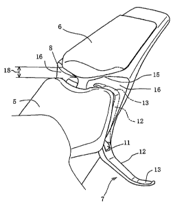
An embodiment of the present invention will now be described. Fig. 1 is a side
view showing principal components in a rear portion of a body of a motorcycle.
A seat rail 1 extending in the longitudinal direction is bent obliquely upward
at
an intermediate portion thereof to form a stepped portion 2, thereby affording
a
raised rear portion 3. On a front portion of the seat rail 1 are supported a
rear
end portion of a fuel tank 4 and a rider seat 5, while on its rear portion is
supported a pillion seat 6.
Under the rider seat 5, one end of a pillion step 7 is secured pivotably to a
side
face of the seat rail 1. Under a lower end of the pillion seat 6, a grip 8 is
supported on the stepped portion 2. A rear wheel 9 is positioned under the
pillion seat 6.
WH-13314/cs
CA 02625131 2008-03-10
-4-
One end of the pillion step 7 is secured pivotably to a mounting lug 11
through a
pivot shaft 10 which is disposed inclinedly forward and obliquely upward, the
mounting lug 11 being attached to a side face of the seat rail 1. The pillion
step 7
has an arm portion 12 and a foot rest portion 13. The arm portion 12 is
provided
at one end thereof with a bifurcated boss portion 14 which is mounted on the
pivot shaft 10 with the mounting lug 11 positioned between the bifurcated
portions.
The pillion step 7 is pivotable within a plane perpendicular to the pivot
shaft 10,
but since the arm portion 12 is oblique with respect to the pivot shaft 10,
the foot
rest portion 13 describes a sectorial locus T in side view. As to the pillion
step 7,
its solid-line position in the figure is a use position, while its phantom-
line
position is a retracted position. When the pillion step is stowed, the foot
rest
portion 13 gets into a gap between the rider seat 5 and the pillion seat 6 and
its
tip end portion is accommodated into a grip space 16 formed in a lower portion
of the grip 8.
Fig. 2 is a perspective view showing a layout state of the rider seat 5 and
the
pillion seat 6. A rear end portion of the rider seat 5 is formed as a stepped
portion 18 which is lower than a front-end upper portion of the grip 8 and
which
faces the grip space 16 formed in the lower portion of the grip 8. The grip
space
16 is formed under the pillion seat 6 and is open sideways and forward behind
the rider seat 5 so as to permit a tip end part of the foot rest portion 13 to
be
received therein.
Fig. 3 is a perspective view of the seat rail 1. The pillion step 7 is secured
to the
mounting lug 11 formed projectingly on the left side face of the seat rail 1.
When
the pillion step 7 is to be stowed, the tip end part of the foot rest portion
13 gets
into the grip space 16 while crossing the space above the stepped portion 2.
The grip 8 is a member which is generally T-shaped in front view. An upper
portion of the grip 8 is formed as a grip portion 15 projecting in the
transverse
direction, a central portion thereof is formed as a leg portion 17 extending
in the
WH-13314/cs
CA 02625131 2008-03-10
-5-
vertical direction, and at a lower end of the leg portion 17 the grip 8 is
secured to
an upper surface of the stepped portion 2.
Under the grip portion 15 and sideways of the leg portion 17 there is formed
the
grip space 16. The grip portion 15 is for the fellow passenger to grip and is
triangular on the right-hand side in plan view. A front edge of the grip
portion
is a slant whose outer side is retracted to ensure a large spacing from the
rear
end portion of the rider seat 5, thereby making easy access to the grip space
16
and ensuring an opening for entering and leaving of the tip end of the foot
rest
10 portion 13.
Fig. 4 is a view showing the pillion step 7 as seen in the direction of the
pivot
shaft 10 which is substantially the front side. The pillion step 7 as a whole
is
generally L-shaped and the arm portion 12 and the foot rest portion 13 are
15 formed continuously and integrally. The foot rest portion 13 moves along
the
locus T centered on the pivot shaft 10, so that the direction of the foot rest
portion
13 in its retracted position and that in its use portion are reverse to each
other.
Even if the foot rest portion 13 projects sideways outwards nearly
perpendicularly in the use position, it in the retracted position faces
sideways
inwards nearly perpendicularly and crosses the space above the stepped portion
2.
The actual pivot shaft 10 is inclined obliquely so as to fairly lie down in
the
horizontal direction, so that the foot rest portion 13 moves in the vertical
direction and thus the height thereof in the retracted position and that in
the use
position are different vertically. In the use position the foot rest portion
13 is
positioned below the seat rail 1 so that the fellow passenger can put his or
her
foot thereon.
Fig. 5 is a side view of the boss portion 14 and Fig. 6 is an enlarged
perspective
view showing a pivot inhibiting structure portion for the boss portion 14. As
shown in these figures, a nut 20 is clamped to one end of the pivot shaft 10
which
is in the shape of a bolt. A locking plate 21 adapted to pivot around the
pivot
shaft 10 is integral with the boss portion 14.
WH-13314/cs
CA 02625131 2008-03-10
-6-
The locking plate 21 is formed with locking grooves 22 in opposite positions
on
both sides of the pivot shaft 10. Upon pivoting of the locking plate 21 to the
use
position or the retracted position, a locking ball 23 (see Fig. 6) which is
provided
beforehand on the mounting lug 11 side comes into engagement with one
locking groove 22 to inhibit the pivotal movement.
Fig. 7 is a sectional view taken on line 7-7 in Fig. 1. In the boss portion 14
provided at one end of the arm portion 12, the mounting lug 11 is fitted in
between a pair of opposed mounting arms 14a and is connected thereto through
the pivot shaft 10. The pivot shaft 10 is, for example, a socket bolt and one
end
thereof is fixed with the nut 20. The locking plate 21 is provided in the boss
portion 14 so as to pivot integrally with the boss portion. The locking
grooves 22
are formed in part of the locking plate 21 and the locking ball 23 which is
provided on the mounting lug 11 side comes into engagement with one locking
groove 22, whereby the locking plate 21 is locked at its pivotal position.
The locking ball 23 is urged projectingly in its locking direction by spring
means
24, e.g., coil spring, and when a locking groove 22 moves onto the locking
ball 23,
the locking ball projects into the locking groove 22 to effect locking. The
locking
grooves 22 are formed in 180 -spaced symmetric positions so as to correspond
to
the retracted position and the use position. The spacing between the locking
grooves 22 may be set freely in accordance with the pivotal angle of the
pillion
step 7. If the locking plate 21 is made separate from the boss portion 14, the
production thereof becomes easier, but it also may be formed directly on an
end
face of the boss portion 14.
Next, the operation of this embodiment will be described. As shown in Figs. 2
to
4, in the use position, the foot rest portion 13 projects sideways outward
nearly
perpendicularly, permitting the fellow passenger to put his or her foot
thereon.
When the pillion step 7 is to be retracted in this state, force acting in the
retracting direction is applied to the pillion step 7, causing the pillion
step to
move pivotally. As a result, the locking ball 23 is pushed out from the
locking
groove 22 concerned against the urging force of the spring means 24 and is
thus
WH-13314/cs
CA 02625131 2008-03-10
-7-
unlocked, whereby the foot rest portion 13 becomes pivotable along the locus
T.
Consequently, the foot rest portion 13 moves within an oblique rotation circle
centered on the pivot shaft 10 and once spreads sideways of the vehicle body,
then gradually approaches the seat rail 1, eventually crosses the space above
the
stepped portion 2 while facing inwards perpendicularly, gets into the gap
between the rear end of the rider seat 5 and the front end of the pillion seat
6, and
its tip end portion is received within the grip space 16 (Fig. 2). Thereafter,
at the
pivotal position the locking ball 22 again engages into a locking groove 22 to
lock
the locking plate.
For movement from the retracted position to the use position there may be
performed operation reverse to the above.
This retracting operation is a mere application of force to the pillion step
7,
causing the pillion step to move pivotally. Thus, the pillion step can be
stowed in
one action without the need of folding up the foot rest portion 13 which is
required in the prior art. Therefore, it becomes possible to perform a quick
operation and the convenience is improved. Besides, when the pillion step 7 is
not used, that is, when there is no fellow passenger, the grip 8 is utilized
effectively and the foot rest portion 13 can be received therein.
Moreover, since the foot rest portion 13 of the pillion step 7 is stowed
positively
between the rear end of the rider seat 5 and the pillion 6, the appearance is
also
improved.
The present invention is not limited to the above embodiment, but various
modifications and applications may be made within the principles of the
present
invention. For example, in case of providing a rear cover which covers at
least a
side portion of the vehicle body under the rider seat, etc., if a recess
capable of
receiving therein the arm portion of the pillion step when retracted is formed
in
the rear cover, the arm portion when retracted is received within the recess
and
does not project from the surface of the rear cover, whereby it is possible to
maintain a smooth flow uniforming surface of the rear cover and hence possible
to decrease the running resistance.
WH-13314/cs
CA 02625131 2008-03-10
-8-
Besides, not only the pillion step can be stowed by utilizing the rear cover
effectively, but also the appearance is improved.
Although various preferred embodiments of the present invention have been
described herein in detail, it will be appreciated by those skilled in the
art, that
variations may be made thereto without departing from the spirit of the
invention or the scope of the appended claims.
WH-13314/cs