Note: Descriptions are shown in the official language in which they were submitted.
Printed. 17-01-2008
DESCTRAN PCT/ES 2006/00a 477`
CA 02625194 2008-04-07
1
R 1
SECTION INSULATOR FOR RIGID CATENARY
DESCRIPTION
OBJECT OF THE INVENTION
The present invention relates to a section insulator developed to be
installed in electrified railway lines, specifically in those wherein the
catenary
which supplies electric voltage to the pantograph is a rigid catenary.
The section insulator for rigid catenary object of this invention has a
dual functionality, since it can exercise the functions both of conventional
section insulator and of neutral section insulator.
BACKGROUND OF THE INVENTION
The rigid catenary is a power system for rail transport alternative to
the conventional catenary and which basically consists of an aluminium
profile with an area in the form of a gripping device which serves as housing
to the copper contact wire whereby it makes contact with the pantograph
table positioned in the (ocomotor roof, thereby capturing the line current.
Despite the fact that its lower maintenance costs compared with
conventional catenaries justify its installation in any part of the line, its
use is
normally almost exclusively restricted to the inside of tunnels since it
reduces
the gauge necessary therein. The fact that this electrification system is not
widely used justifies that most of the section insulators are designed to be
adapted to conventional catenaries and not rigid catenaries.
The overhead contact lines installed to supply electricity to the railway
lines are subdivided in different sections or electric circuits to thus
guarantee
its operating availability. This sectioned design of the electrical
installation
enables the insulation of each of the sections independently, so that the
power supply can be interrupted without having to cut the current supply to
the entire installation. In this way, in the event that a fault occurs in one
or
several sections comprising the line (either the service is interrupted in a
planned manner to perform periodic maintenance work or repair in the event
of fault) the power supply is guaranteed, and therefore the operation of those
sections that are not affected by said circumstances, thus avoiding the
interruption of the rail, traffic throughout the line.
To achieve this purpose, the aforementioned section insulators are
used, which consist of insulating elements which, positioned between two
1/1.2;
17-09-2007
Printed. 17-01-2008 DESCTRAN PCT/ES 2006/000 477
2
adjacent sections of overhead contact line, interrupt the electrical
continuity
between said sections although they guarantee the mechanical continuity
between both, thus allowing the passage of the pantographs. The section
insulators should maintain the electric voltage in the pantograph,
guaranteeing that the protection devices of the rolling stock are not affected
nor are operating malfunctions created therein, thus avoiding the
unnecessary triggering of the protection apparatus. Therefore, the
configuration of said section insulators should be such that it permits the
pantograph to come into contact with one of the ends of the insulator before
losing contact with the other end. The most typical solutions in the state of
the art consist of disposing two shoes which guarantee the continuity of the
current at the time of passage through the insulator or splitting the contact
wire in two, thus establishing a common contact area.
To electrically separate two adjacent sections of the overhead line
supplied from two different substations the so-called neutral sections are
interposed between said sections. The interposition of these sections
enables separating sections between which there is a power difference, in
the case of DC, or even a phase difference in the event that the feed current
of the catenary is AC. The application is even known of neutral sections of
considerable length in transition areas between the supply of DC and AC
current, thus making a light rail system compatible with the metro system or
even the network of regional trains. In classic designs, the neutral section
is
defined by the intermediate space, insulated or earthed, which is created
between two section insulators or two air gap insulations.
As in the case of the section insulators, the neutral sections, aside
from electrically insulating the two sections between which they are
installed,
must guarantee the mechanical continuity between both so that they enable
the smooth passage of the pantograph. Nevertheless, unlike what occurs in
the case of conventional section insulators, when the pantograph traverses
the neutral section, the electrical derivations between the sections that said
neutral section separates must be avoided. For this reason, to reduce the
appearance of electric arcs, some systems use track magnets which
automatically disconnect the power of the rolling stock when this
approximates the neutral section, re-establishing the power immediately after
crossing it, for which reason it incorporates a second set of magnets of a
function programmed for "time out" in the system which controls the traction
2 12' CA 02625194 2008-04-07 17-09 2007;
Printed: 17-017200 8' DESCTRAN POT/ ES 2006/000.477
3
of the train or electric traction vehicle concerned.
Despite the fact that, as has been indicated, the rigid catenary is an
electrification system which is not widely used and, therefore, most of the
existing insulator designs do not adapt to this type of overhead line, there
are
some appropriate designs for its installation in this type of catenary.
Thus, for example, an insulator assembly can be found in the state of
the art applicable to rigid catenaries which is inserted between two conductor
rail bars, the ends of said insulator having the same profile as the conductor
rail wherein it is inserted. The central part of the insulator is made of a
material of great dielectric and mechanical rigidity, so that it complies with
the requirements of this type of device: on the one hand, it interrupts the
electrical continuity between the two conductor rail bars and further
guarantees the mechanical continuity between both, permitting the passage
of the pantographs. Shoes are mounted on each side of the insulator, in
longitudinal direction, which receive the passage of the pantograph, the
central part remaining at an upper level, for which reason the pantograph
only rests on the side shoes and not on said central part.
The previous insulator assembly has the advantage that compared
with other known insulators it can act as both section insulator and neutral
section insulator by doing no more than establishing the appropriate
electrical connections in each case. For this purpose, the insulator has
copper strips which allow making bridging connections, so that the side
shoes remain electrified, thus guaranteeing the power supply to the
pantograph during its passage through the insulator. However, when the
operating requirements demand the existence of a neutral zone, the bridging
cables are removed and in this way, the side shoes are not electrified, so
that the pantograph stops being electrically supplied on passing through the
central zone which, on being electrically insulated, starts to behave'as a
neutral area. This functionality, however, obliges introducing a great
separation between the side shoes in order to main the necessary safety
distances to guarantee the electrical insulation between the different
components.
Among this device's deficiencies, and which the insulator object of this
invention tries to resolve, we should highlight the difference between the
mechanical properties of the rigid catenary and the section insulator, which
causes a discontinuity in the vertical rigidity of the system which leads to
the
3/ 2' CA 02625194 2008-04-07 17-09.2007
Printed; 17-01-2008' DESCTRAN' PCT/ES 2006/000 477
4
appearance of hard points, with the consequent deterioration of the current
capturing quality when configured as section insulator.
On the other hand, an undesirable behaviour of this type of section
insulator has been observed in combination with pantographs which have a
non-uniform wear of the collecting shoes, a phenomenon which is closely
linked to the distance between the side shoes already mentioned. On
passing through the insulator,, the pantograph first rests on the contact wire
inserted in the conductor rail profiles positioned at the ends and later in
the
side shoes of the central zone, which are found at the same height as said
wire. On passing through the intermediate zone, wherein the three wires
overlap, if the pantograph table is new or has uniform wear, the support is
produced correctly and, therefore, the insulator's behaviour is that desired.
However, on the occasions wherein the collecting shoe of the pantograph
has a high degree of irregular wear, said wear being greater in the central
area, there is a high risk of a collision of the sides of the table with the
side
shoes of the insulator. Sudden bumps against the shoes produce the
breaking thereof and, furthermore, as a consequence of the bump, contact
losses may occur with the central wire, increasing the wear caused by the
appearance of electric arcs.
To avoid these bumps insofar as is possible, it is necessary to adjust
the height of the shoes acting on the vertical studs which support them, thus
avoiding the collision of the pantograph with the side shoes, even in the case
that the pantograph in question has the table worn. Despite the fact that this
solution is very simple, it is not of practical use, since logically, the wear
of
the table of each one of the pantographs which traverse the insulator will
considerably vary from one to another, which means it would be necessary
to adjust the height of the shoes prior to the passage of each vehicle, which
is absolutely infeasible. However, this solution causes a geometric continuity
in the height of the different elements of the section insulator, in addition
to
requiring frequent maintenance operations.
In light of the above, the objective of the present invention is to
develop an insulator for rigid catenary which performs the dual function of
section insulator, interrupting the electrical continuity between the sections
when necessary, and neutral section, guaranteeing in both cases sufficient
mechanical continuity between the catenary and the insulator to permit the
smooth passage of the pantograph. It is likewise desirable that the insulator
4/12 CA 02625194 2008-04-07
17-0020(17
Printed, 17-01-2008 DESCTRAN' PCT/ES 2006[000 477-:
in question overcomes the drawbacks of the similar known devices, which
means that their configuration should be such that it minimizes the need for
adjustment and maintenance and has, insofar as is possible, similar
mechanical properties to those of the rigid catenary wherein it is installed.
5 DESCRIPTION OF THE INVENTION
The invention consists of a section insulator for rigid catenary which
has a dual functionality since it can exercise the functions both of
conventional section insulator and neutral section insulator. In other words,
the object of this invention is an insulating element which, positioned
between two adjacent sections of the rigid catenary, interrupts the electrical
continuity between them, separating them electrically when required,
nevertheless maintaining a mechanical continuity such that it allows the
smooth passage of the pantograph.
In order to guarantee that the transition of the pantograph through the
insulator is easily produced, i.e. without bumps and uniformly, the insulator
described below adapts to the geometric and mechanical characteristics, i.e.
linear weight or vertical rigidity, of the conductor rail of the rigid
catenary
wherein it is installed.
Compared with the insulators known at present, which as has been
previously seen normally comprise two side shoes which extend parallel to
the direction of the catenary, the insulator which is being described
comprises a single shoe obliquely disposed with respect to the direction of
the catenary, thus guaranteeing the symmetry of the assembly. This
characteristic configuration of the insulator permits a much more compact
design to be obtained which considerably reduces the sudden bumps
between the collecting shoe of the pantograph and the shoe of the section
insulator, which thus minimizes the need for adjustment and maintenance.
Another added advantage, consequence of the insulator's configuration, is
that it reduces the wear of both the wire and the pantograph table, which
leads to a reduction in the maintenance operations and, consequently, to an
economic saving.
The main element of the insulator being described is the
aforementioned shoe, which is disposed between two conductor rail
segments. Said segments join to the ends of each section of the catenary by
connection flanges similar to those used to join the aluminium bars which
compose the rigid catenary. These segments have identical properties to
511` CA 02625194 2008-04-07
17-09.2007:
Printed ; 17-01-2008 DESCTRAN` PCT/ES 2006/000 477
6
those of the rigid catenary wherein the insulator is installed, since they
have
the same configuration, i.e. the same profile, and they are normally made in
the same material. In this way, it achieves that both the linear weight and
the
vertical rigidity of said segments are similar to those of the conductor rail.
The similarity in the configuration of the segments and in the conductor rail
of
the catenary further guarantees the continuity of the contact wire between
the section insulator and the rigid catenary, since said wire extends
throughout each one of the segments.
The insulator shoe comprises an insulating piece whose base rests on
both ends of the insulator, i.e. on the upper part of the previous conductor
rail segments, a core disposed in direction vertical, so that the insulating
piece has T-shaped cross-section, and a wire conductor, hereinafter called
insulator wire and normally copper, disposed on the lower part of said core.
The base of the insulating piece is oriented in the same direction as the two
segments whereon it rests, thus giving continuity to the catenary, although
the core of this insulating piece, and consequently the insulator wire fixed
on
its lower part, are obliquely disposed with respect to said direction. The
fixing
of the insulator wire to the core of the insulating piece is performed through
pieces, called clamps, disposed on said core, as will be seen in detail below.
The insulator wire, which is the element which acts as shoe, extends beyond
the length of the core of the insulating piece, its two ends being outside
said
core and curved upwards.
To guarantee the correct breaking of the electric arc when abandoning
the first section, preformed copper wires called sparks are added to the ends
of each one of the conductor rail segments. The introduction of these
elements has the purpose that the electric arc breaks in them and, therefore,
these sparks will be the elements which undergo most wear of the section
insulator. To facilitate the replacement of said elements, the incorporation
of
an opening mechanism has been considered which permits replacing them
quickly and simply. Said opening mechanisms are disposed at the ends of
each one of the two conductor rail segments, which remain opposite the
shoe of the section insulator.
In order to adjust the behaviour of the insulator, allowing it to
electrically supply the pantograph or behave as a neutral section, connecting
strips of conductor material have been incorporated, normally, copper, which
allow the bridging of the central shoe by a bridging cable, normally also
6/12 CA 02625194 2008-04-07 17-09-2407.
Printed: 17-01-2008 DESCTRAN PCTIES 20061000 477'
7
copper. This cable is fixed, by one of its ends, to one of said connecting
strips, whilst the other end is fixed to a bore made for said purpose in the
end of the insulator or to a connecting clamp or similar positioned in the
upper part of the adjacent rigid catenary.
In principle, the connecting strips can be placed at any of the two
ends of the insulator equally, i.e. both at its entry and at its exit.
However, if
said strips were fixed to the insulator exit, the breakage of the electric arc
will
occur at the ends of the central shoe, whilst its installation at the entry of
the
insulator is more advantageous since the electric arc breaks in copper wires
previously called sparks, which, as has been advanced, can easily be
replaced as they are pieces of short length fixed at the end of the insulator
by different opening mechanisms. For this reason, the strips are installed at
the entry of the insulator and not at its exit.
When the insulator is bridged, i.e. a bridging wire is installed between
one of its ends and a connecting strip, the distance between the electrically
insulated conductor elements, i.e. the central shoe and the output spark, is
less than the width of the pantograph table, for which reason its power
supply is ensured at all times since, before the table loses contact with the
insulator wire, it is already in contact with the output spark, which is
subjected to the corresponding supply voltage.
However, when the insulator is not bridged, the insulator shoe lacks
electric voltage, for which reason the distance between the electrically
insulated conductor elements, i.e. between the input spark and the output
spark, is greater than the width of the pantograph table, which means this
lacks power supply during its passage through the insulator, which in this
situation behaves as a neutral section.
The spark wires are fixed, by one of their ends, to each one of the two
conductor rail segments between which the central shoe extends, whilst their
free end rests directly on the base of the insulating piece of the central
shoe
in order to avoid undesired vertical movements. In order to permit an easy
adjustment of the spark height, thus guaranteeing the smooth passage of the
pantograph and allowing height differences to be compensated due to the
wear of said elements, the incorporation of a height adjustment system has
been considered, which comprises, among other elements which will be
detailed below, a bolt which extends from the base of the insulating piece
and the lower end whereof is introduced in the free end of the spark.
7112 , CA 02625194 2008-04-07 11-09-2007,'
Printed: 17-01-2008 DESCTRAN PCT/ES 2006/000 477
8
DESCRIPTION OF THE DRAWINGS
To complement the description being made and with the object of
helping towards a better understanding of the characteristics of the
invention,
in accordance with a preferred example of practical embodiment thereof, a
set of figures is attached as an integral part of the description, wherein the
following has been represented with an illustrative non-limitative character:
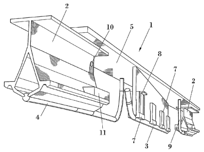
Figure 1. Shows a perspective view of the section insulator for rigid
catenary object of this invention.
Figure 2. Shows an elevation view of the section insulator of figure 1.
Figure 3. Shows the section produced by the C-C plane of figure 2.
Figure 4. Shows the section produced by the B-B plane of figure 2.
Figure 5. Shows the section produced by the A-A plane of figure 3 and
corresponds to the fixing system of the insulator wire to the
core of the insulating piece.
Figure 6. Shows the section produced by the D-D plane of figure 2 and
corresponds to the opening mechanism incorporated in the
conductor rail segments.
Figure 7. Shows a view of the detail indicated as E in figure 2 and
corresponds to the height adjustment system of the spark
wires.
PREFERRED EMBODIMENT OF THE INVENTION
In light of the figures, we can observe therein an example of
embodiment of the invention, which consists of a section insulator for rigid
catenary which basically comprises two conductor rail segments (2), with
their corresponding sparks (9) and the opening mechanisms to facilitate their
replacement, and a central shoe (1) obliquely disposed between both
segments (2), and which can be bridged at convenience, as will be seen
below.
Figure 1 shows a perspective view of the section insulator which is
being described, and therein we can clearly observe how the central shoe (1)
is disposed between two conductor rail segments (2), consisting of an
aluminium profile at the lower end whereof a contact wire (4) of the rigid
catenary is secured. The physical constitution of the insulator is also
clearly
shown in figure 2, which corresponds to an elevation view of the previous
figure. The profile of both segments (2) exactly corresponds'to the conductor
rail comprising the rest of the catenary, for which reason said segments (2)
8/12' CA 02625194 2008-04-07 17-09-20,07
Printed: 17-01-2008.` DESCTRAN PCT/ES 2006/000 477
9
have the same properties as the catenary, whereto they are joined by
connection flanges. In the figures.that comprise this description, and with
the
object of simplifying them insofar as is possible, the section insulator has
exclusively been represented and not the conductor rails of the catenary
wherein it is installed and, therefore, the connection flanges neither.
Since the profile of said segments (2) is the same as that which
constitutes the conductor rail of the catenary, the contact wire (4) is fixed
to
the segments (2), as in the rest of the catenary, by insertion of the wire (4)
in
the housing determined by the two lower ends of said profile. Despite the
fact that in this description, and in the accompanying figures, reference is
made to a determined conductor rail profile, it includes the possibility that
the
insulator described adapts to any rigid catenary, whereby the profile of the
segments (2) comprising said insulator will be the same as that of the
catenary in question.
As has previously been mentioned, and with the object of
guaranteeing the correct breakage of the electric arc when abandoning the
first section, each one of the conductor rail segments (2) incorporates a
preformed copper wire called sparks (9). The spark wires (9) are disposed,
as with the contact wire (4), in the lower part of the profile in question,
positioning one of the ends of said sparks (9) adjacent with respect to the
contact wire (4), i.e. the wire comprising each one of the two sparks (9) is
the
extension of the contact wire (4), with respect to which it extends obliquely.
The oblique arrangement of the two spark wires (9) is observed more clearly
in figure 3, wherein it is observed how both wires (9) extend parallel to one
another and with respect to the core (6) of the insulating piece.
One of the ends of each spark wire (9) is fixed to the corresponding
conductor rail segment (2) by an opening mechanism, whose constitution is
observed in figure 6, which will be seen below, which allows them to be
replaced more quickly and simply. The opposite end of the sparks (9), which,
from the height corresponding to that of the contact wire (4) of the catenary,
describe a curved path until reaching the base (5) of the insulating piece, is
fixed by means of a height adjustment system to said base (5), so that
undesired vertical movements are avoided.
Figure 7 shows said adjustment system in detail, which basically
comprises a bolt (16), two hold-down nuts (17) and several washers (18, 19).
The stem of the bolt (16) traverses the base (5) of the insulating piece and
is
9112,' CA 02625194 2008-04-07 17-09-2007<
7 01 -2008. DESCTRAN PCTIES 2006/000 477
Printed: 17-0,1-20.06'
= 10
introduced in the spark wire (9), its head remaining on the upper surface of
said base (5) and its lower end housed in said wire (9). In order to
immobilize
the bolt (16), a washer (18) is interposed between its head and the upper
surface of the base (5) of the insulating piece, which, additionally,
increases
the support area bolt (16) head and avoids scratching the base (5). Two
hold-down nuts (17) are threaded to the stem of the previous bolt (16), one
of them opposite the lower surface of the base (5) of the insulating piece and
the other opposite the upper section of the spark wire (9). The adjustment
system further comprises different elastic washers (19) which, inserted
between the two hold-down nuts (17) and the surfaces which they oppose,
avoid the threaded joints from loosening. Via this system, the sparks (9)
height can be easily adjusted to guarantee the smooth passage of the
pantograph and to compensate the possible height differences due to the
wear of said elements.
As has been advanced, in order to facilitate the replacement of the
spark wires (9), which, as they are the elements wherein the electric arc
breaks, are subject to greater wear than that of the other elements
constituting the insulator, they join the corresponding conductor rail segment
(2) through an opening mechanism, represented in detail in figure 6. Said
mechanism is basically composed of two side pieces (11), two inner pieces
(12) of the same length as the previous, two through-bolts (13) and a central
bolt (14).
The two side pieces (11) included in each one of the two opening
mechanisms have a configuration such that they adapt to the conductor rail
segment (2) by their outer surface, for which reason said configuration will
vary depending on the profile of the catenary wherein the insulator is going
to
be installed. Two inner pieces (12) of equal length to the previous one and
opposite them are installed on the inner surface of the conductor rail
segment (2). Two through-bolts .(13) at each end are bolted to the side
pieces (11) and keep the assembly together, whilst the central bolt (14),
positioned between the two through-bolts (13), and which, unlike them, is not
a through-bolt, abuts against one of the inner pieces (12), its tightening
causing the separation of the two lower ends of the profile comprising the
conductor rail segment (2) and the consequent opening of the housing
wherein the spark wire (9) is inserted, which allows it to be replaced by
another one simply. The opening mechanism is completed with a series of
10/12- CA 02625194 2008-04-07 17-09-2007
Printed: 17-01-2008 DESCTRAN, PCT/ES 2006/000 477'
11
washers (15) which, interposed between the head of the central bolt (14) and.
the side piece (11) wherein said bolt (14) is bolted, prevent the tightening
thereof and, therefore, the opening of the housing. Nevertheless, when it is
necessary to replace the spark wire (9), said washers (15) should be
removed thus enabling the tightening of the central bolt (14), which causes
the separation of the lower ends of the conductor rail segment (2). In figure
6, which corresponds to the section produced by the D-D plane of figure 2,
the opening mechanism has been represented in closed state, i.e. with the
washers (15) inserted between the head of the central bolt (14) and the side
piece (11).
The central shoe (1) disposed between both segments (2) is basically
comprised of an insulating piece whose cross section is T-shaped, which has
a horizontal part, called base (5) and a vertical part or core (6), diagonally
disposed. The material comprising this insulating piece can be, for example,
resin and fibreglass, although it covers the possibility of using any other
material which, having other mechanical properties which are acceptable and
suitable for this application, guarantees the required electrical insulation.
The
oblique arrangement of the core (6) of this insulating piece is observed with
greater clarity in figure 3, which corresponds to the section produced by the
C-C plane of figure 2. The joining of this central shoe (1) to the rest of the
catenary is performed through the base (5) of the insulating piece, which, as
is observed in figures 2 and 4, rests on the conductor rail segments (2) and
is bolted to them. The length of the core (6) of this insulating piece is less
than that of the base (5), with respect to which it is diagonally disposed
thus
guaranteeing the symmetry of the assembly. The joining of the insulator wire
(3) to said core is performed via a series of clamps (7), as has been
represented in figure 5, which corresponds to the section produced by the A-
A plane of figure 3. In said figure we can observe the clamps (7) whereby the
insulator wire (3) is fixed to the core (6) of the insulating piece. These
clamps
(7) have a protuberance on the lower part which perfectly adapts to the
grooves of the insulator wire (3). The concave shape of the lower side of the
clamps (7) only allows them to come into contact with the core (6) in the
upper zone, thus guaranteeing that the clamps (7) firmly secure the insulator.
wire (3) in the lower zone. The clamps (7) also have a recess on their lower
surface designed to house the connecting strips (8) which allows the shoe
(1) to be bridged, as has previously been indicated, by a copper bridging
11/12 CA 02625194 2008-04-07 17-09-20074
Printed 17-01-2008 DESCTRAN ` PICT /E 2006[0004 77
= 12
cable which extends from said connecting strip (8) to a bore (10) made for
said purpose in the conductor rail segment (2) or a connection clamp or
similar positioned in the upper part of the adjacent rigid catenary.
12/1 `2 CA 02625194 2008-04-07 17-09-2007'.