Note: Descriptions are shown in the official language in which they were submitted.
CA 02625545 2010-10-07
SYSTEMS AND METHODS FOR MATERIAL AUTHENTICATION
BACKGROUND
[0001] Herein disclosed are embodiments generally relating to imaging members
and assemblies and the authentication of specific material components used in
the
imaging members and assemblies.
[0002] The disclosed embodiments may be used in various printing systems, such
as for example, in phase change or solid ink jet printing systems or
electrophotographic
printing systems. Authentication of the materials ensures that compatible
components
are being used with the imaging members and assemblies. More specifically, the
embodiments disclose a system and method for efficiently detecting whether
materials
being used in the imaging members and assemblies are compatible and authentic
materials authorized for such uses.
[0003] Manufacturers of the various imaging members and assemblies produce
materials and components specific for use with these imaging members and
assemblies. The materials are tailored to each member or assembly for optimal
performance. A problem arises when materials, used in the imaging members and
assemblies, not authorized by the manufacturers are substituted for the
authentic
counterparts. Use of these unauthentic materials causes compatibility issues
and has a
significant negative impact on the imaging business and reputation of the
manufacturers. The unauthentic materials often are not as compatible with the
imaging
member or assembly as advertised and subsequently introduce operational
problems
that negatively impact machine performance. Such problems lead to higher
maintenance costs, increased down-time, and the like. These type of problems
in turn
lead to lower customer satisfaction with the imaging members and assemblies.
[0004] Previous attempts to devise a monitoring system with which to determine
the authenticity of imaging materials were problematic in that the systems did
not
provide easy detection of the unauthentic or unauthorized materials involved.
The
systems generally did not detect the unauthentic materials until after an
extended
period of problematic behavior raised suspicions, and subsequently involved
obtaining
1
CA 02625545 2010-10-07
samples from the dissatisfied customer and conducting extensive and costly
laboratory
analysis to determine authenticity.
[0005] As such, the previous attempts did not yield an effective way in which
to deal
with the issue of unauthentic materials. Therefore, there is a need for a way
in which to
efficiently detect the presence of unauthentic materials used in an imaging
member or
assembly without taking up a large amount of time and resources.
[0006] The term "electrostatographic" is generally used interchangeably with
the
term "electrophotographic."
BRIEF SUMMARY
[0007] According to embodiments illustrated herein, there is provided a system
and
method for more efficiently detecting whether materials being used in the
imaging
members and assemblies are compatible and authentic materials authorized for
such
uses.
[0008] In particular, an embodiment provides a method for authenticating an
electrostatographic material, comprising:
tagging an electrostatographic material with at least one fluorescent tag,
wherein the fluorescent tag is present in the electrostatographic material in
an amount
of from about 0.01 to about 100 ppm;
generating an energy source for stimulating an emission of fluorescent light
from the fluorescent tagged electrostatographic material;
stimulating the emission of fluorescent light from the fluorescent tagged
electrostatographic material;
subjecting the stimulated emission of fluorescent light from the fluorescent
tagged electrostatographic material to a filter to remove background
interference before
measuring the emission of fluorescent light from the fluorescent tagged
electrostatographic material at the predetermined wavelength, wherein the
filter is
selected from the group consisting of an acousto-optic tunable filter, a fiber
tunable
filter, a thin-film interference filter, an optical band-pass filter, and a
digital filter;
measuring the emission of fluorescent light from the fluorescent tagged
electrostatographic material at a predetermined wavelength; and
2
CA 02625545 2010-10-07
identifying a test electrostatographic material as authentic when the
measured emission of fluorescent light from the test electrostatographic
material meets
a predetermined emission of fluorescent light from the fluorescent tagged
electrostatographic material at the predetermined wavelength.
[0009] In another embodiment, there is provided an electrostatographic
material
comprising a fuser fluid and at least one fluorescent tag. In specific
embodiments, the
electrostatographic material is prepared for use with the above described
method. For
example, the electrostatographic material is prepared to be identified as
authentic by
the above described method.
[0010] Further embodiments provide method for authenticating an
electrostatographic material, comprising:
tagging an electrostatographic material with at least one fluorescent tag,
wherein the fluorescent tag is present in the electrostatographic material in
an amount
of from about 0.01 to about 100 ppm;
generating an energy source for stimulating an emission of fluorescent light
from the fluorescent tagged electrostatographic material;
stimulating the emission of fluorescent light from the fluorescent tagged
electrostatographic material;
subjecting the stimulated emission of fluorescent light from the fluorescent
tagged electrostatographic material to a filter to remove background
interference before
measuring the emission of fluorescent light from the fluorescent tagged
electrostatographic material at the predetermined wavelength, wherein the
filter is
selected from the group consisting of an acousto-optic tunable filter, a fiber
tunable
filter, a thin-film interference filter, an optical band-pass filter, and a
digital filter;
measuring the emission of fluorescent light from the fluorescent tagged
electrostatographic material at a predetermined wavelength; and
identifying a test electrostatographic material as authentic when the
measured emission of fluorescent light from the test electrostatographic
material meets
a predetermined emission of fluorescent light from the fluorescent tagged
electrostatographic material at the predetermined wavelength.
3
CA 02625545 2010-10-07
BRIEF DESCRIPTION OF THE DRAWINGS
[0011] For a better understanding of the present invention, reference may be
had to
the accompanying figures.
[0012] Figure 1 is a cross-sectional view of a fusing system;
[0013] Figure 2 is a cross-section view of a web-cleaning fusing system;
[0014] Figure 3A is a cross-sectional view of a transfix system with an image
on the
drum surface being transfixed to a sheet of final substrate by passing through
the
transfix nip;
[0015] Figure 3B is a cross-sectional view of a drum maintenance (DM) and
imaging
cycle; and
[0016] Figure 4 is a schematic block diagram of a system for authenticating a
material for use in imaging systems according to an embodiment of the present
disclosure.
3a
CA 02625545 2010-10-07
DETAILED DESCRIPTION
[0017] In the following description, it is understood that other embodiments
may be
utilized and structural and operational changes may be made without departure
from
the scope of the present embodiments disclosed herein.
[0018] The present embodiments provide a system and method for detecting the
presence of unauthentic materials used in imaging apparatuses in a time and
cost-
efficient manner. The present embodiments propose to incorporate a chemical
tag in
specific imaging materials that can be traced online or offline. The
incorporated tags do
not affect the performance of the imaging materials. In embodiments, the tag
molecule
is a fluorescent tag that is detected by fluorescence. In further embodiments,
the tag is
colorless in order to broaden the tag concentration latitude.
[0019] Use of a fluorescent tag for identification is known in the
biotechnological
field. For example, such tags have been used as part of a molecule that
researchers
have chemically attached to aid in the detection of the molecule to which it
has been
attached. The fluorescent molecule is also known as a fluorophore.
[0020] Use of similar tags have also been introduced into toner particles for
use in
custom color control techniques, as disclosed in U.S. Patent No. 6,002,893.
The
disclosure teaches a novel sensor adapted to sense fluorescent molecules in
the toner
particles to provide a color independent measure of total toner solids.
[0021] The present embodiments, the imaging materials include any materials
that are used in various imaging systems known in the art. For example,
specific
embodiments described herein include adding a tag molecule in small quantities
into imaging materials used in piezoelectric ink jet (PIJ) and solid ink jet
(SIJ)
printing systems as well as electrostatographic materials used in xerographic
systems for monitoring and evaluating authenticity. In one embodiment, the tag
can be incorporated into fusing system materials and components generally used
in electrostatographic printing systems, such as the fuser fluid or release
fluid/oil.
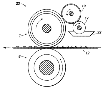
Typical fusing systems are described in U.S. Patent Nos. 5,166,031, 5,736,250,
and 6,733,839. As can be seen in Figure 1, the fuser fluid or fuser release
oil
can be present in several locations throughout the fusing system 23, for
4
CA 02625545 2011-01-05
example, in the fluid sump 22, on the surfaces of the metering roll 17, donor
roll 19,
fuser roll 1, pressure roll 8, and ultimately on the media 12 passing through
the fusing
system 23. The fuser fluid to be evaluated can be obtained from any of these
locations.
Other embodiments include incorporating the tag into fuser web-cleaning system
materials and components, such as the fuser lubricant, or incorporating the
tag into
drum maintenance materials and components in a transfix system, such as the
drum
maintenance fluid. Typical web-cleaning fusing systems are described in U.S.
Patent
Nos. 4,929,983, 5,045,890, and 6,876,832. Web-cleaning fusing systems are
generally
used in, but not limited to, electrostatographic printing systems. Typical
transfix systems
are described in U.S. Patent. Nos. 5,389,958, 5,805,191, and 6,176,575.
Transfix
systems are typically used in piezoelectric ink jet or solid ink jet printing
systems.
[0022] As seen in Figure. 2, the fuser lubricant can be present in many
locations in
the web-cleaning system 56, for example, the cleaning web 48, fuser roll 50,
pressure
roll 52, and ultimately on the media 54 passing through the web-cleaning
fusing system
56. The fuser lubricant to be evaluated can be obtained from any of these
locations.
Likewise, the drum maintenance fluid can be present in several locations
throughout
the drum maintenance system, as shown in Figures 3A and 3B, including the
surface of
the drum maintenance roller 58, metering blade 60, drum surface 62, transfix
roller 64,
and ultimately on the print media 66 passing through the transfix system.
Again, the
drum maintenance fluid to be evaluated can be obtained from any of these
locations.
[0023] In embodiments, the electrostatographic material comprises a fuser
fluid and
at least one fluorescent tag. In a specific embodiment, the
electrostatographic material
is prepared for use with the system and methods described herein. For example,
the
electrostatographic material is prepared to be identified as authentic by the
system and
methods. The tag comprises a fluorescence or scintillation chemical.
Fluorescent or
scintillating materials are those materials exhibiting fluorescence while
being acted
upon by radiant energy such as ultraviolet (UV) rays or X-rays. Suitable
materials may
be solid or liquid, organic or inorganic, and include, for example, any well-
known
fluorescent crystals or fluorescent dyes. As previously mentioned,
CA 02625545 2008-03-14
fluorescent dyes have been typically used in tagging molecules in chemical or
biochemical research.
[0024] Any known fluorescent dyes may be used. Suitable dyes include, for
example, fluorescein, rhodamine, rosaline, uranium europium, uranium-
sensitized
europium, and mixtures thereof. Organic compounds may also be used. Those that
have been tested to be solvent compatible with fuser fluids include
poly(methylphenyl
siloxane), 1,4-Bis(4-methyl -5-phenyloxazol-2-yl) benzene, 1,4-Bis(5-phenyl
oxazol-2-yl)
benzene, 2,5-diphenyl oxazole, 1,4-Bis(2-methyl styryl) benzene, trans-4,4'-
diphenyl
stilbebene, 9,10-diphenyl anthracene, and mixtures thereof. Positions of the
fluorescence band for toluene range from about 350 nm to about 420 nm while
being
radiated with ultraviolet rays having wavelengths of 365 nm. In addition, the
present
embodiments also contemplate using fluorescence tags which can fluoresce in
all
different visible colors, namely from about 350nm to about 700nm.
[0025] In embodiments, the fluorescent material is capable of exhibiting
fluorescence in small amounts. Consequently, the fluorescent tag can be added
in
small amounts to the imaging material without altering the properties or
performance of
the tagged material. The present embodiments provide for a fluorescent tag
that is
present in the tagged imaging material in an amount of from about 0.001 to
about
10,000 ppm, in an amount of from about 0.001 to about 1,000 ppm, or in an
amount
from about 0.01 to about 100ppm.
[0026] Methods used to "treat" or incorporate the fluorescent tag into the
imaging
material, may be physical in nature, chemical in nature or a combination of
both. For
example, a physical treatment method may involve simple mixing of the fuser
fluid with
the fluorescent material, or a chemical treatment method may involve bonding
the
fluorescent tag to the fuser fluid by any suitable technique. If the tag
comprises a
fluorescent material that is not sufficiently soluble in the tagged material,
the insolubility
can be addressed by modifying the molecule with a moiety compatible with the
tagged
material. In one embodiment, for increasing the solubility of a fluorescent
tag in fuser
fluid, the moiety is a short silicone chain.
[0027] In embodiments, a method for authenticating an imaging material,
comprises tagging an imaging material with the fluorescent tag described
above, and
6
CA 02625545 2008-03-14
measuring the level of fluorescence emitted. An energy source, such as radiant
energy,
is generated and directed to a material to be assessed for authenticity. The
energy
source will stimulate an emission of fluorescent light from the fluorescent
tag if the
evaluated material contains one. Any fluorescence that is stimulated from the
evaluated
imaging material is measured. The measurement may be set at a predetermined
wavelength that is set to only pick up fluorescence from the authentic imaging
materials.
Fluorescence that meets the predetermined values is identified as authentic.
Furthermore, the method may include subjecting the emission of fluorescent
light from
the imaging material to a filter to remove background fluorescence or
interference
before measuring the emission of fluorescent light from the material at the
predetermined wavelength. In certain arrangements, where the sensors (and
their
filters) are placed in close proximity to the tagged material, the detector
are able to
detect the fluorescence of the material without additional optics. However, if
other
considerations force the detectors to be placed at some distance from the
tagged
material, then it may be advantageous to also include collection optics
between the
material being tested and the detector to gather and focus the fluorescent
light from the
tested material onto the detector(s).
[0028] In further embodiments, as shown in Figure 4, a system 5 for
authenticating an imaging material 10 obtained from an imaging assembly 15 is
provided. The system comprises a fluorescent tag used to tag
electrostatographic
materials used in the imaging assembly. The system provides an energy source
20 for
stimulating an emission 25 of fluorescent light from the electrostatographic
material 10,
and a fluorescent detector 30 for measuring the emission 25 of fluorescent
light from the
electrostatographic material 10 at a predetermined wavelength. In addition to
the
commonly used UV illumination systems, the energy source 20 could be a cost-
effective
UV light emitting diode (LED). For example, such a UV LED may have a peak
emission
wavelength of 365nm and a narrow spectrum half width, e.g., 10 nm. The
fluorescent
detector 30 includes an indicator 35 for identifying the evaluated
electrostatographic
material 10 as authentic when the measured emission 25 of fluorescent light,
if any,
from the electrostatographic material 10 meets the predetermined wavelength.
The
indicator 35 may be a part of the detector 30, for example, a display screen
disposed on
7
CA 02625545 2008-03-14
the detector. The indicator 35 may also be a separate component not attached
to the
detector, for example, a remote personal computer that remotely communicates
with the
detector 30 via a wired or wireless network. In embodiments, the fluorescent
detector
30 detects light within a visible spectrum. In further embodiments, the
detector 30
comprises multiple sensors.
[0029] In addition, the system 5 may further include a smart chip 40 coupled
to
the fluorescence detector 30 for requesting replacement of the evaluated
material when
the material is not authentic. An optical filter 45 may be included in the
system 5 to
remove background fluorescence or interference that may be involved in the
evaluation
of the electrostatographic material 10. Such filters may include, for example,
an
acousto-optic tunable filter, a fiber tunable, a thin-film interference
filter, or an optical
band-pass filter. Thin-film filters may be interference filter wheels or
interference filter
turrets. In further embodiments, a "digital" filter may be used to distinguish
fluorescence
from the fluorescent tag from that of other interferences or contaminants that
may also
cause a test imaging material to fluoresce. Digital filtering involves
measuring
fluorescent intensity in a range of wavelength. A plot of intensity versus
wavelength
shows peaks, each being characterized by a set of fluorescent parameters
(e.g.,
fluorescent wavelength, intensity, and full width at half maximum (FWHM)). By
comparing these parameters, one can isolate the fluorescent parameter unique
to the
specific tag. For example, among the superimposed intensity curve, only one
peak is
due to the fluorescent tag. Thus, by fitting the entire intensity curve with
peaks
identified for each of the fluorescent parameters associated with the tag
(fluorescent
wavelength, intensity, and FWHM), the digital modeling process can be used to
distinguish the fluorescent tag from the other fluorescent
interferences/contaminants.
[0030] While the description above refers to particular embodiments, it will
be
understood that many modifications may be made without departing from the
spirit
thereof. The accompanying claims are intended to cover such modifications as
would
fall within the true scope and spirit of embodiments herein.
[0031] The presently disclosed embodiments are, therefore, to be considered in
all respects as illustrative and not restrictive, the scope of embodiments
being indicated
by the appended claims rather than the foregoing description. All changes that
come
8
p k CA 02625545 2008-03-14
within the meaning of and range of equivalency of the claims are intended to
be
embraced therein.
EXAMPLE
[0032] The example set forth herein below and is illustrative of different
compositions and conditions that can be used in practicing the present
embodiments.
All proportions are by weight unless otherwise indicated. It will be apparent,
however,
that the embodiments can be practiced with many types of compositions and can
have
many different uses in accordance with the disclosure above and as pointed out
hereinafter.
[0033] Example 1
[0034] A typical fusing system (e.g., electrostatographic printing system),
includes a fuser roll, a pressure roll , a printing medium, an image, a
metering roll, a
donor roll, a release agent sump, and a fuser fluid or fuser release oil. In
this example,
the fuser fluid is treated with a fluorescent tag.
[0035] An ultraviolet lamp is radiated onto the fluorescent tagged fuser fluid
in the
sump, and fluorescence intensity is measured as a function of wavelength. The
measured fluorescence spectrum is then fit to a model in which the model
parameters
are compared with predetermined values, for example, predetermined
wavelengths,
stored in a fluorescence detection device. The fuser fluid is authenticated if
the model
parameters meet the stored values.
[0036] As the model parameters are dependent on the location of the detection,
for example, where in the fusing system the tested fuser fluid is obtained
from, and
thereby the parameters are dependent on the amount and temperature of the
fuser
fluid.
[0037] Example 2
[0038] A typical solid ink jet (SIJ) printing system includes a drum
maintenance
and imaging cycle. An image on the drum surface is transfixed to a sheet of
final
substrate by passage through the transfix nip. The drum maintenance roller
then cleans
and applied drum maintenance fluid to the drum before the image is jetted. In
this
example, the drum maintenance fluid is treated with a fluorescent tag.
9
CA 02625545 2008-03-14
Poly(methylphenyl siloxane), which is readily soluble in typical silicone-
based drum
maintenance fluids, may be used as the fluorescent tag molecule in this
example.
[0039] An ultraviolet lamp is radiated on the fluorescent tagged drum
maintenance fluid in the drum maintenance system. The fluorescence intensity
is
measured as a function of wavelength. The measured fluorescence spectrum is
then fit
to a model in which the model parameters are compared with predetermined
values, for
example, predetermined wavelengths, stored in a fluorescence detection device.
The
drum maintenance fluid is authenticated if the model parameters meet the
stored
values.
[0040] As the model parameters are dependent on the location of the detection,
for example, where in the drum maintenance system the tested drum maintenance
fluid
is obtained from, and thereby the parameters are dependent on the amount and
temperature of the drum maintenance fluid.
[0041] Fluoranthene (99%), available from Sigma-Aldrich Co. (St. Louis,
Missouri) and fluorescent clear blue dye (Invisible Blue), available from Risk
Reactor
(Huntington Beach, California), were tested as fluorescent tags. It was noted
that
fluoranthene (99%) was soluble in a variety of organic solvents, and miscible
in silicone,
while fluorescent clear blue dye had limited solubility in methyl ethyl ketone
(MEK).
[0042] The fluoranthene (99%) and fluorescent clear blue dye were first
dissolved
in appropriate solvents and then added directly to SIJ silicone fluid for
evaluation of
fluorescent tag effectiveness. The following samples were used in the
evaluation: (1)
5g of drum maintenance fluid alone, (2) 5g of drum maintenance fluid with 0.2g
of 5%
fluoranthene in acetone (0.2% of fluoranthene), and (3) 5g of drum maintenance
fluid
with 0.2g of 5% fluorescent clear blue dye in MEK (0.2% of DFSB-C0).
[0043] Ten drops, or approximately 80 mg were spin-coated onto two-inch square
304V stainless steel plates and two-inch square card-stock paper samples.
Small drops
were placed directly onto a fourth stainless steel plate for comparative
evaluation. The
samples were evaluated for visibility of the tag in the sample under a black
light.
Fluorescence of the fluorescent tags in silicone oil showed good visibility.
[0044] It was further noted that the paper substrate also fluoresces under
black
light. Thus, using proper filtering techniques before imaging fluorescence
signals in the
CA 02625545 2008-03-14
samples would amplify the differences in fluorescence signal between the
control
sample and samples with fluorescent tags.
[0045] Example 3
[0046] A typical web-cleaning fusing system (e.g., electrostatographic
printing
system) includes a fuser roll having a TEFLON outer layer. Such a fuser roll
generally
does not require a fuser release agent. Although the TEFLON outer layer has a
very
low surface energy (thereby having sufficient release properties), it is still
desirable to
use a cleaning web for removal of paper dust or a very small quantity of
residual toner
on the surface. The cleaning web is largely improved by impregnated lubricant,
such as
silicone oil. In this example, the fuser lubricant is treated with a
fluorescent tag.
[0047] An ultraviolet lamp is radiated on the fluorescent tagged drum fuser
lubricant in the web-cleaning fusing system. The fluorescence intensity is
measured as
a function of wavelength. The measured fluorescence spectrum is then fit to a
model in
which the model parameters are compared with predetermined values, for
example,
predetermined wavelengths, stored in a fluorescence detection device. The
evaluated
fuser lubricant is authenticated if the model parameters meet the stored
values.
[0048] As the model parameters are dependent on the location of the detection,
for example, where in the web-cleaning fusing system the tested fuser
lubricant is
obtained from, and thereby the parameters are dependent on the amount and
temperature of the fuser lubricant.
[0049] All the patents and applications referred to herein are hereby
incorporated
by reference in their entirety in the instant specification.
[0050] It will be appreciated that various of the above-disclosed and other
features and functions, or alternatives thereof, may be desirably combined
into many
other different systems or applications. Also that various presently
unforeseen or
unanticipated alternatives, modifications, variations or improvements therein
may be
subsequently made by those skilled in the art which are also intended to be
encompassed by the following claims. Unless specifically recited in a claim,
steps or
components of claims should not be implied or imported from the specification
or any
other claims as to any particular order, number, position, size, shape, angle,
color, or
material.
11