Note: Descriptions are shown in the official language in which they were submitted.
CA 02625592 2008-04-08
WO 2007/030783 PCT/US2006/035189
TITLE
Breathing Apparatus
CROSS REFERENCE TO RELATED APPLICATIONS
[0001] This application clainis priority to and the benefit of United States
Provisional Patent Application Serial No. 601715,476 filed September 9, 2005,
the
entire disclosure of which is herein incorporated by reference.
GOVERNMENT SPONSORED RESEARCH
[0002] A portion of the development of this invention was supported by U.S.
ARMY RDECOM ACQUISITION CENTER through Contract No. W91CRB-06-
0019. Therefore, the United States Govermnent may have certain rights with
regard
to this invention.
I
CA 02625592 2008-04-08
WO 2007/030783 PCT/US2006/035189
BACKGROUND OF THE INVENTION
[0003] 1. Field of the hivention
[0004] This invention relates to a self contained breatliing apparatus, and
more
particularly to a breatliing apparatus comprising a hood surrounding a user's
head
and sealed about the user's neck, and for which the internal atmospliere is
actively
scrubbed and enhanced with oxygen.
[0005] 2. Description of Related Art
[0006] Concerns over the threat of a terrorist's use of chemical, biological,
radiological, or nuclear (CBRN) weapons has prompted an increased interest in
the
effectiveness of breathing apparatuses that can be used in an emergency to
allow
emergency personnel to operate in a contaminated area, or to allow for
protection of
occupants during the evacuation of a contaminated building or mass transit
vehicle.
[0007] While some types of breathing apparatuses already exist, they often
fall
short of meeting desired performance characteristics. Revised standards
recently
developed by the National Institute for Occtipational Safety and Health
(NIOSH) for
protective breathing apparatuses for use in countering CBRN threats have
created
increased performance demands, particularly related to maximum carbon dioxide
(COZ) levels and minimum oxygen flow rates, that cannot be met by most
existing
breathing apparatuses. NIOSH requires a minimum oxygen flow rate of three
liters
per minute (3 lpm) for the entire fifteen minute specified duration of use of
the
apparatus, and a maximum COz level of 3%.
[0008] Passive scrubbing techniques are generally unable to maintain the
NIOSH required COZ level of 3%. Active scrubbing techniques are known to be
more effective in removing CO2. Many active scrubbers, however, require the
user
2
CA 02625592 2008-04-08
WO 2007/030783 PCT/US2006/035189
to breathe directly tlirougli a cartridge containing a CO2 adsorbent chemical.
Directly scrubbed respiration requires an interface between the user and the
scrubber, such as a mouth bit with a nose clip or a mouth and nose cup. Many
people are uncomfortable or physically unable to use a mouth bit or cup due to
facial
hair or the like and such a device greatly reduces the iiser's ability to
communicate,
which can be particularly problematic in emergency situations. Additionally,
breathing directly through the adsorbent cartridge increases the worlc of
breathing.
[0009] Many einergency breathing apparatuses include a hood that encloses a
user's head and which not only aids in protecting sensitive areas about the
face and
within the respiratory system, but also allows the elimination of any mouth
bit or
cup. A problem particularly associated with such hoods, however, is the
elevated
temperature within such a hood during use. Exhaled air is raised in
temperature due
to internal body temperature. Additionally, a users head radiates body heat
that is
absorbed by the air in the hood. Further cheniical scrubbers often utilize
exothennic
reactions adding more heat to the air within the hood. Not only may such
increased
temperature be uncomfortable, but also when the air being breathed is heated,
the
result can be severe impairment in overall functioning of the user wearing the
breathing apparatus, and worse, difficulty in breathing and even respiratory
burns.
3
CA 02625592 2008-04-08
WO 2007/030783 PCT/US2006/035189
SUMMARY OF THE INVENTION
[0010] The following summary of the invention is provided to give the reader a
basic understanding of some aspects of the invention. This summary is not
intended
to identify key or critical elements of the invention or to delineate the
scope of the
invention. The sole purpose of this section is to present some concepts of the
invention in a simplified form as a prelude to the more detailed description
that is
presented in a later section.
[0011] At least in part due to the problenls discussed in the Background
section
and otller problems in the art, described herein is a breathing apparatus
providing
breathable air within a hood surrounding a user's head. The apparatus utilizes
active
scrubbing to remove carbon dioxide by circulating the air out of the hood and
tlirough a housing containing purification elements. The housing also includes
a
heat sink that is able to cool the circulated air.
[0012] Also described herein is a method for cooling air circulated within a
breathing apparatus, the method including operating an air pump to circulate
the air
within a breathing apparatus so that the circulated air comes into contact
with a heat
sink to which the air releases heat. In an embodiment, a compressed oxygen gas
cylinder releasing oxygen acts as a driver for a Venturi device that functions
as an air
pump and acts as a heat sink.
4
CA 02625592 2008-04-08
WO 2007/030783 PCT/US2006/035189
BRIEF DESCRIPTION OF THE DRAWINGS
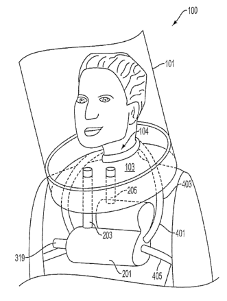
[0013] FIG. 1 provides a perspective view of an embodiment of a breathing
apparatus as worn by a user.
[00141 FIG. 2 provides a cross-sectional view of a housing assembly of an
embodiment of a breathing apparatus.
[0015] FIG. 3 provides a cut-away perspective view of an alternate
embodiment of a housing assembly.
CA 02625592 2008-04-08
WO 2007/030783 PCT/US2006/035189
DETAILED DESCRIPTION OF PREFERRED EMBODIMENTS
[0016] An embodiment of a breathing apparatus (100) is shown in FIG. 1, and
generally comprises a hood (101) and a housing (201). The hood (101) surrounds
the user's head and contains a breathable atmosphere. The housing (201) holds
elelnents that function to provide air purification and oxygen enrichinent for
the
atmosphere within the hood (101), thereby providing support for the
respiration of
the user wearing the hood (101). Such a breathing apparatus (100) is designed
to
provide protection from dangerous external environments, such as are presented
by,
though not limited to, smoke or fire, or chemical, biological, radiological or
nuclear
hazards, that might otherwise negatively impact any or all of the biological
and
physiological functions central to a user's head, such as sight and
respiration and so
many other bodily functions that can be detrimentally impacted by inhaled
hazards.
[0017] An aspect of the apparatus (100) is a hood (101) that is large enougll
to
surround a person's head. The hood (101) is constructed at least in part of a
transparent or translucent material through which the user can see when
wearing the
hood (101). The hood (101) includes a neck seal subassembly (103), which
provides
an opening (104) througli which a user's head is moved when donning the hood
(101). In an embodiment, the neck seal subassembly (103) functions like an
elastomeric membrane allowing the opening (104) to expand to allow a user's
head
into the hood (101) and then to contract to seal snuggly around the user's
neck,
essentially separating the environment inside the hood (101)-an internal
voh.ime in
which resides the user's head-from the environment outside the hood (101).
[0018] Another aspect of the apparatus (100) is an enclosed housing (201). In
an embodiment, such as is shown in FIG. 2, the housing (201) includes multiple
6
CA 02625592 2008-04-08
WO 2007/030783 PCT/US2006/035189
intenial chambers. As shown in FIG. 2, the chanzbers of the housing (201)
reside
internal to the housing (201), and are connected one to another to allow air
flow
tlierebetween througli the housing (201). In an embodiment, the chambers are
coiuiected so as to create a flow path having a beginning and an end, thereby
allowing generally unidirectional air flow through the housing (201) in the
direction
of such flow path from beginning to end. In an embodiment, the chambers of
such a
housing (201) are connected to the internal volume of a hood (101) at both the
beginning and end of such flow path. As shown in FIG. 1, in an embodiment,
such
connection is made via two hoses, one hood output hose (205) connecting the
internal hood volume to the beginning of the housing flow path, and one hood
input
hose (203) connecting the end of the housing flow path to the internal hood
volume.
Such a connection between the housing (201) and the hood (101) creates a
closed
volume comprising the internal hood voluine, the housing chamber volume, and
the
hose volumes, and further creates a self contained circulation path for air to
move
from the internal volume of the hood (101), through the chambers of the
housing
(201), and back to the liood (101). Through such closed volume, along such
circulation path, air can flow in a recirculating manner. In this regard, the
hood
output hose (205) provides a path for air in the internal hood volume to exit
the hood
(101) and to enter the chambers of the housing (201), and the hood input hose
(203)
provides a path for air to exit the chambers of the housing (201) and enter
the
internal hood volume.
[0019] FIG. 2 shows a cross-sectional view of an embodiment of a housing
(201) having a generally unidirectional flow path depicted using a series of
arrows
pointing into the housing (201) from output hose (205), pointing from one
chamber
7
CA 02625592 2008-04-08
WO 2007/030783 PCT/US2006/035189
to anotlier witliin the housing (201), and pointing from an air pump (305)
into the
input hose (203). Iii this embodiment, elements within the chambers of the
housing
(201) include a scrubber (307), an oxygen source (301), and an air pump (305).
In
the embodiment shown in FIG. 2, the air pump (305) is a Venturi device, which
is
used to pull air from the chainbers of the housing (201) and push this air
into the
internal hood volunie through input hose (203). This air pump (305) sets up
the
recirculation of air within the closed system that is comprised by the
breathing
apparatus (100).
[0020] In the embodiment shown in FIG. 2 the Venturi device is powered by
the jet stream output from a coinpressed gas cylinder (304) that is an oxygen
enrichment source (301). While in other embodiments, other oxygen enrichment
sources (301), such as solid state chemical oxygen generators, are used, the
depicted
embodiment utilizes a compressed gas cylinder (304). The cylinder (304) of
compressed oxygen gas is attached to a regulator (303) for controlling release
of
oxygen from the cylinder (304) through regulation of the flow rate thereof. To
start
the flow of oxygen from the cylinder (304) prior to donning the hood (101), a
user
operates an actuator (319), which in an embodiment is a spring biased pin that
punctures a gasket of the cylinder (304) to release the compressed gas
contained
therein.
[0021] In the embodiment shown in FIG. 2, the cylinder (304) is mounted
within a chanlber of the housing (201) having an internal rib structure. The
ribs
(321) run parallel to the direction of the flow path (as marked by arrows in
FIG. 2)
within the housing (201). While the cylinder (304) is securely held in place
by
contact with the tops of the ribs (321), the troughs between ribs (321)
provide
8
CA 02625592 2008-04-08
WO 2007/030783 PCT/US2006/035189
chamiels for air flow to continue tlvrough this chamber around the cylinder
(304). In
otlier enibodiments, other stnYctures, such as fingers, provide secure
positioning for
the cylinder (304) and allow air flow around the cylinder (304). In an
embodiment,
the cylinder (304) initially is pressurized to about 3000 psi, and contains
about 60
liters of pure oxygen gas. In an embodiment, the regulator allows an oxygen
flow
rate in the range of about two liters per minute to about six liters per
minute, and
more preferably in the range of about three liters per minute to about four
liters per
minute.
[0022] As mentioned above, in an embodiment the air pump (305) is a Venturi
device, the operation of which is based upon the flow of oxygen out of the
pressurized cylinder (304). As this flow of oxygen passes through the Venturi
device, the decreased pressure therein draws air from around the cylinder
(304) into
the flow within the Venturi device, inducing a mixing of recycled air with the
oxygen released from the cylinder (304). This drawing of air into the Venturi
device
for mixing with the pure oxygen from the cylinder (304) is the source of a
flow
amplification defined by the ratio between the oxygen gas flow rate entering
the
Venturi device and the mixed gas flow rate exiting the Venturi device. In a
preferred
embodiment, the Venturi device creates a flow amplification of approximately
13 to
1(i.e., 41pin oxygen flow entrains 521pm of air). In this way, recycled air
pulled
from the internal hood volume and through the housing (201) is mixed with
oxygen
ejected from the cylinder (304) and the mixture is provided through input hose
(203)
into the internal hood volume and thereby back to the user.
[0023] While the air pump (305) is operating, air from inside the hood (101)
is
pulled througli output hose (205) into the housing (201). In the course of the
air's
9
CA 02625592 2008-04-08
WO 2007/030783 PCT/US2006/035189
path tlirougli the housing (201), the air passes through one or more
purification
devices, which may include but is not limited to particulate filtration or
chemical
purification, sucli as catalytic oxidation or adsorption. In the embodiment
shown in
FIG. 2, air purification occurs as a result of air passage tliough a
purification
cartridge (307), which removes carbon dioxide from the air. In alfiernate
einbodiments the cartridge (307) may also remove other unwanted components of
the air, including moisture. The cartridge (307) in this embodiment comprises
a
solid chemical substrate that chemically adsorbs or otherwise separates carbon
dioxide fiom the air drawn from the internal hood volume. Carbon dioxide must
be
removed because of the constant enrichnient with carbon dioxide of the air
within
the internal hood volume due to the user's respiration. In alternate
embodiments, the
cartridge (307) is filled with granular material, sheet material, or material
in another
form. In a preferred embodiment, an ExtendAire Lithium HR COZ adsorbent
cartridge manufactured by Micropore, Inc. is utilized as the filter cartridge
(307).
ExtendAirOO cartridges comprise a relatively new form of lithium hydroxide
adsorbent that has been formed into sheets rather than being provided as
traditional
granules. The sheet adsorbent is formed to include ribs such that when the
sheet is
rolled the ribs create channels between the sheets through which air can flow.
ExtendAir cartridges provide more efficient carbon dioxide scrubbing and
therefore last longer than an equivalent amount of granular adsorbent, as well
as
generating lower adsorption reaction temperatures, therefore adding less heat
to the
air passing through the cartridge (307).
[0024] Another aspect of the embodiment shown in FIG. 1 is a harness (401)
that hooks about the user's neck and chest to provide support for the housing
(201)
CA 02625592 2008-04-08
WO 2007/030783 PCT/US2006/035189
near the user's head and therefore near the hood (101). The harness (401) in
the
depicted einbodiment is desigiied to support the housing (201) on the front of
the
user's torso utilizing two straps, a neck strap (403) and a torso strap (405).
This
design allows for hands free operation and for reduced encumbrance to the
activities
of the user, since the housing (201) is held closely to the user's chest. In
other
embodiments, other harness configurations are used to support the housing
(201) at a
convenient location relative to the user, including in various enzbodiments,
near the
user's waist and on the user's back.
[0025] The apparatus (100) will generally be stored prior to use in a vacuum
sealed barrier pouch that is intended to be opened only at the time the
apparatus
(100) will be used, such as when needed to be donned quickly in an emergency.
Such sealed storage maintains the cleanliness of the apparatus (100) and the
functional capabilities of the purification device, such as cartridge (307).
For
instance, without a sealed barrier about the apparatus (100), carbon dioxide
from the
ainbient atmosphere could deplete the ability of the purification device to
remove
carbon dioxide from the air within the hood (101) wllen being worn by a user.
[0026] To use the apparatus (100) shown in FIG. 1, a user will generally
remove the device from the vacuum-sealed barrier pouch by tearing open the
vacuum-sealed pouch and removing the apparatus (100). In another step, the
user
places the neck strap (403) around the back of the user's neck allowing the
housing
(201) to rest on the user's chest. The torso strap (405) is secured around the
user's
back and onto the opposite side of the housing (201). This configuration
allows for
all strap connections to be maintained in front of the user for easy control,
as well as
11
CA 02625592 2008-04-08
WO 2007/030783 PCT/US2006/035189
placing the mass of the housing (201) close to the user's chest, a relatively
comfortable and convenient location.
[00271 The user operates an actuator (319), a portion of which is accessible
external to the housing (201). Operation of the actuator (319) begins the flow
of
oxygen through a regulator (303) and into the hood (101). The user will
generally
place both hands inside the neck seal subassembly (103) opening (104) with
palms
facing each other, expand the opening (104) by spreading apart these hands,
and
slide the opening (104) over the user's head so the user's head is positioned
inside
the hood (101). The user then removes the user's hands from the opening (104)
allowing the neck seal subassembly (103) to seal securely around the user's
neck.
The user may adjust the harness (401) as needed for comfort and mobility.
[0028] The user can breathe normally inside the hood (101), which generally
will gradually start to inflate, since the user's consumption of oxygen is
generally
less than the volume of oxygen added from the oxygen source (301) in any given
time period. Too, so that the addition of oxygen to the internal volume of the
hood
(101) does not result in too great an internal pressure, there is, in an
embodiment, a
pressure relief valve on the hood (101), which relieves internal pressure to
the
ambient atmosphere outside the hood (101) when the pressure inside the hood
(101)
reaches a preset threshold value. In another embodiment, pressure internal to
the
hood (101) is released through the neck seal subassembly (103), which seal
automatically opens momentarily upon the internal hood pressure reaching a
threshold value, tliereby releasing some of the pressure before the seal
automatically
closes again.
12
CA 02625592 2008-04-08
WO 2007/030783 PCT/US2006/035189
[0029] Wlien the oxygen source (301) is depleted, the hood (101) will start to
deflate indicating that the hood (101) needs to be removed or a new source of
oxygen started. By the time of such a deflation, if no new oxygen source is
available
for the hood (101), the user should have moved to an area with a non-hazardous
atYnosphere so that the user may safely remove the apparatus (100).
[0030] In an embodiment such as shown in either FIG. 2 or FIG. 3, when
oxygen flow commences, generally upon initial operation of the actuator (319),
this
flow of oxygen from cylinder (304) is plumbed into the Venturi device (305) in
a
direction relative to the geometry tliereof so as to produce a Venturi effect
therein,
which draws additional air into the Venturi device from within the housing
(201).
The circulated air flow drawn into the air pump (305) by the Venturi effect is
deliberately engineered to flow adjacent to the compressed oxygen cylinder
(304), in
an embodiment, as a result of the arrangement of elements within the housing
(201).
Such deliberately engineered air flow places the flowing air in contact with
the
exterior surface of the cylinder (304). Contact between the circulating air
and the
cylinder allows heat to be removed from the air to the cylinder (304). In this
way the
cylinder (304) operates as a heat sink. In other embodiments, other devices,
such as
a Peltier device, act as a heat sink to reniove heat from the flowing air.
[0031] In an embodiment such as is shown in either of FIGS. 2 or 3, the
removal of heat from the flowing air occurs because the cylinder (304) is
cooled
when the compressed gas inside of the cylinder (304) is released, as is
predicted by
the generalized ideal gas law. Notably, as the pressure in the cylinder (304)
decreases due to release of oxygen therefrom, the temperature of tlle oxygen
in the
cylinder (304) decreases, tlius, so does the temperature of the cylinder
(304), itself,
13
CA 02625592 2008-04-08
WO 2007/030783 PCT/US2006/035189
due to the physical interaction between the cylinder (304) and the oxygen
contained
therein. Therefore, as the oxygen leaves the pressurized cylinder (304)
reducing the
pressure in the cylinder (304), the external surface of the cylinder (304)
will cool.
This is particularly noticeable if the material of which the cylinder (304) is
constnicted is effective at conducting heat, such as if it is constructed of
metal.
[0032] As for embodiments such as are shown in either of FIGS. 2 or 3, prior
to flowing around the cylinder (304), the recirculated air is drawn through
the
purification cartridge (307) or scrubber containing a chemical carbon dioxide
adsorbent. The chemical process for removing carbon dioxide is generally
exothermic, thus heating the air considerably. In addition, heat is added to
the air in
the hood (101) as a result of the user's body temperature, both by radiation
from the
user's head and convection due to the user's respiration. This increased air
temperature can be problematic during use of the apparatus (100), since
providing
hot air to a user can injure the user and also can cause exhaustion more
quickly.
However, in an embodiment, heated air is cooled by passage over the cylinder
(304)
as described above, thereby moderating the effect of heating by the scrubber
and the
user's body. Further moderation of the added heat is obtained as a result of
the
mixing between the recirculated air and the pure oxygen released from the
cylinder
(304), which oxygen is cooled through depressurizing release from the cylinder
(304). In this way, i.e., interaction of recirculated air with the cooled
cylinder (304)
and the cooled oxygen, at a minimum, the temperattire in the hood (101) is
maintained lower or is increased more slowly than if such cooling did not
occux.
Furthermore, the cooling effect provided by the cooled cylinder (304) can also
condense and thereby remove water vapor from the air.
14
CA 02625592 2008-04-08
WO 2007/030783 PCT/US2006/035189
[0033] To summarize the inovenzent of the air within the apparatus (100)
shown in FIG. 1 as driven by the air pump (305), which, in an embodiment as
described here, includes the purification and puniping elements of the
embodiments
shown in FIGS. 2 or 3: the user's exhaled air is drawn out of the hood (101)
and
/
into the housing (201) via outlet hose (205). In the housing (201), the
exhaled air is
then drawn through the purification cartridge (307) where carbon dioxide is
adsorbed chemically, witll heat being generated and transferred to the air as
an
undesirable product of the reaction. The scrubbed air is drawn over the
dispensing
oxygen cylinder (304), in an embodiinent through channels formed by ribs
(321).
Passage of the air over the cylinder (304) allows the cylinder (304) to absorb
heat,
aided by the endothermic reduction in pressure of the gas in the cylinder
(304) as
such gas is released therefrom. In an embodiment, the cooled cylinder (304)
will
also condense residual moisture vapor from the air. The cylinder (304)
supplies
cool, supplementary oxygen to the air flow and thereby provides the motive
flow to
produce the Venturi effect through the air pump (305). The oxygen and recycled
air
mixture are directed back to the hood (101) from the housing (201) through
inlet
hose (203). This closed loop system maintains sufficiently low internal carbon
dioxide levels, sufficiently high oxygen levels, and a moderate temperature
within
the llood (101) so as to produce a relatively comfortable environment for the
user.
Further, because exhaust air is reused, unused oxygen is preserved in the
recirculating flow, thereby increasing the length of time the hood (101) can
be used.
[0034] In an embodiment, such as is shown in FIG. 3, this flow traverses a
flow
path that is generally vertically oriented. That is, in an embodiment, the
housing
(201) shown in FIG. 3 is designed to be positioned under the hood, as is the
housing
CA 02625592 2008-04-08
WO 2007/030783 PCT/US2006/035189
(201) shown in FIG. 1. The flow patli in such an embodiment is such that air
travels
generally linearly down out of the hood (101) into the housing (201), through
the
cartridge (307), to the bottom of the flow path before generally reversing
direction to
travel up past the cylinder (304), tlirough the Venturi device (305) and into
the hood
(101). As shown in FIG. 3, in an embodiment, the cylinder (304) resides within
a
fairly open, unobstructed chamber within the housing (201), allowing for a
generally
unobstructed flow path past the cylinder (304), especially as conzpared to the
einbodiment with ribs (321) as shown in FIG. 2.
[0035] While the invention has been disclosed in conjunction with a
description of certain embodiments, including those that are currently
believed to be
the preferred embodiments, the detailed description is intended to be
illustrative and
should not be understood to limit the scope of the present disclosure. As
would be
understood by one of ordinary skill in the art, embodiments other than those
described in detail herein are encompassed by the present invention.
Modifications
and variations of the described embodiments may be made without departing from
the spirit and scope of the invention.
16