Note: Descriptions are shown in the official language in which they were submitted.
CA 02625772 2013-05-14
=
=
- 1 -
ARC FAULT CIRCUIT INTERRUPTER AND METHOD FOR DISABLING
SERIES ARC PROTECTION DURING CURRENT TRANSIENTS
BACKGROUND OF THE INVENTION
Field of the Invention
This invention relates generally to circuit interrupters and, more
particularly, to circuit interrupters including an arc fault trip mechanism
which
responds to sputtering arc faults. The invention also relates to methods for
providing series arc protection for electrical circuits.
Background Information
Arcing is a luminous discharge of electricity across an insulating
medium, usually accompanied by the partial volatilization of electrodes. An
arc
fault is an unintentional arcing condition in an electrical circuit. Arc
faults can be
caused, for instance, by worn insulation between adjacent bared conductors, by
exposed ends between broken conductors, by faulty electrical connections, and
in
other situations where conducting elements are in close proximity.
Arc faults in systems can be intermittent since the magnetic
repulsion forces generated by the arc current force the conductors apart to
extinguish the arc. Mechanical forces then bring the conductors together again
in
order that another arc is struck.
Circuit interrupters include, for example, circuit breakers, contactors,
motor starters, motor controllers, other load controllers and receptacles
having a
trip mechanism. Circuit breakers are generally old and well known in the art.
Circuit breakers are used to protect electrical circuitry from damage due to
an
overcurrent condition, such as an overload condition or a relatively high
level short
circuit or fault condition. In small circuit breakers, commonly referred to as
miniature circuit breakers, used for residential and light commercial
applications,
such protection is typically provided by a thermal-magnetic trip device. This
trip
device includes a bimetal, which is heated and bends in response to a
persistent
overcurrent condition.
CA 02625772 2008-04-09
WO 2007/045976
PCT/1B2006/002923
-2-.
The bimetal, in turn, unlatches a spring powered operating mechanism, which
opens
the separable contacts of the circuit breaker to interrupt current flow in the
protected
power system. An armature, which is attracted by the sizable magnetic forces
generated by a short circuit or fault, also unlatches, or trips, the operating
mechanism.
Recently, there has been considerable interest in providing protection
against arc faults. Because of their intermittent and high impedance nature,
arc faults
do not generate currents of either sufficient instantaneous magnitude or
sufficient
average RMS current to trip the conventional circuit interrupter. Even so, the
arcs can
cause damage or start a fire if they occur near combustible material. It is
not practical
to simply lower the pick-up currents on conventional circuit breakers, as
there are
many typical loads, which draw similar currents and would, therefore, cause
nuisance
trips. Consequently, separate electrical circuits have been developed for
responding
to arc faults. See, for example, U.S. Patent Nos. 5,224,006; and 5,691,869.
For example, an arc fault circuit interrupter (AFCI) is a device
intended to mitigate the effects of arc faults by functioning to deenergize an
electrical
circuit when an arc fault is detected. Non-limiting examples of AFCIs include:
(1) arc
fault circuit breakers; (2) branch/feeder arc fault circuit interrupters,
which are
intended to be installed at the origin of a branch circuit or feeder, such as
a
panelboard, and which may provide protection from ground faults (e.g., greater
than
40 mA) and line-to-neutral faults (e.g., greater than 75 A); (3) outlet
circuit arc fault
circuit interrupters, which are intended to be installed at a branch circuit
outlet, such
as an outlet box, in order to provide protection of cord sets and power-supply
cords
connected to it (when provided with receptacle outlets) against the unwanted
effects
of arcing, and which may provide protection from line-to-ground faults (e.g.,
greater
than 75 A) and line-to-neutral faults (e.g., 5 to 30 A, and greater than 75
A); (4) cord
arc fault circuit interrupters, which are intended to be connected to a
receptacle outlet,
in order to provide protection to an integral or separate power supply cord;
(5)
combination arc fault circuit interrupters, which function as either a
branch/feeder or
an outlet circuit AFCI; and (6) portable arc fault circuit interrupters, which
are
intended to be connected to a receptacle outlet and provided with one or more
outlets.
UL 1699 is a specification that governs the performance of AFCI
products including branch/feeder type (AVZQ); outlet circuit type (AWCG);
portable
CA 02625772 2008-04-09
WO 2007/045976 PCT/1B2006/002923
- 3 -
type (AWDO); cord type (AWAY); and combination type (AWAH) AFCIs. A
carbonized path arc clearing time test is conducted in which the total
clearing time
before the AFCI trips shall not exceed specified arc test clearing times based
upon
different levels of test current (i.e., 5 A; 10 A; 15 A or 20 A; 22.5A or
30A). UL
1699 requires that the combination type AFCI must detect and interrupt the
parallel
combination of compressor and arc within a one-second clearing time for an arc
test
current of 5 A (resistive load).
UL 1699 specifies detection of series arcs only when loads on an
associated electric distribution system are in steady-state operation.
The step application of a load voltage often results in significant load
current transients. When a load is energized in an electrical power
distribution
system, there can be an initial transient current that decays into a periodic,
stable
current when the load reaches steady-state operation. In many cases, this is
due to
energy storage in the load, such as capacitive elements (which store energy in
electric
fields) or inductive elements (which store energy in magnetic fields). When a
forcing
function (e.g., a 60 Hz, 120 VRMS voltage source) is applied to a load, the
load current
exhibits a "natural" response which decays with the time constant(s) of the
load, and a
"forced" or "steady-state" response. The initial burst of increased current
when the
load is first energized performs the function of supplying stored energy
required for
the load to operate normally. For example, the initial transient of a computer
load
with a rectifier/capacitor input characteristic is due to capacitive energy
storage, the
initial transient of an electric motor is due to inductive energy storage, and
the initial
transient of a vacuum sweeper is due to inductive energy storage and the
load's initial
inertial energy storage.
Initial current transients may also result from load characteristics other
than energy storage. One example of this is the impedance of an incandescent
light,
which varies greatly over the normal range of operating temperatures. When
voltage
is applied to incandescent lights at room temperature, the light-producing
elements
rapidly heat up to a steady-state temperature, which is accompanied by a
significant
increase in impedance and a consequent drop in current. An example of step
voltage
application lA and current response 1B in incandescent lighting controlled by
a
dimmer (not shown) is shown in Figure 1.
CA 02625772 2008-04-09
WO 2007/045976 PCT/1B2006/002923
- 4 -
In contrast to the step application of load voltage, series arcs cause
relatively minor variations in load voltage and current. For example, for a 60
Hz, 120
VRms voltage source, when an arc occurs in series with a load, the sustained
arc
voltage can be about 20 to about 40 VPEAK, depending on the conditions that
create the
arc. The arc voltage is subtracted from the source voltage, so that when an
arc occurs,
the voltage excitation at the load declines by about 10% to about 20%. The
onset of
series arcing is not accompanied by a load current transient like the type
that
accompanies a step application of voltage. Compared to current transients
associated
with applying a step voltage to a load, there is no dramatic change in the
amplitude of
the load currents. Figure 2 shows series arc voltage 1C, load voltage 1D and
load
current lE versus time for the onset of arcing in series with dimmer-
controlled
incandescent lighting (not shown) in which the arc is produced by using a
carbon-
copper arc generator (e.g., as specified by UL 1699, 58.1.3) in series with
the load.
As a result, step voltages (such as, for example, applying a voltage
source to an unenergized load) can cause major variations in load current,
while series
arcs tend to cause only relatively minor variations in load current. Hence,
any series
arc detection algorithm must ignore major variations in load current and trip
only on
relatively minor variations in load current. It is believed that this
conclusion flies in
the face of conventional arc fault detection practice, particularly for
parallel arc
detection algorithms in which minor variations in load current are ignored and
major
variations in load current are considered the arc signatures of primary
interest.
United States Patent Application Serial No. 10/895,158 discloses that
various arc fault algorithms clear a trip tally value whenever the load
current exceeds
a predetermined limit (e.g., 45 A; 30 ARms) for series arc protection (e.g.,
series arc
protection is defined by UL 1699).
There is, therefore, room for improvement in arc fault circuit
interrupters and methods for providing series arc protection.
SUMMARY OF THE INVENTION
These needs and others are met by the present invention, which
mitigates nuisance trips by disabling series arc protection when current
transients
associated with load energization are detected. For example, this identifies
current
transients that exhibit a single high initial inrush, and temporarily disables
series arc
CA 02625772 2008-04-09
WO 2007/045976 PCT/1B2006/002923
- 5 -
detection (and thereby nuisance tripping) until any such high initial inrush
current
transient has passed. A current inrush detector determines whether a current
inrush
has happened relatively recently. A current "chaos detector" determines how
much
the current has relatively recently exhibited major amplitude fluctuations.
Based upon
this information, series arc protection is enabled at appropriate times; that
is, any time
that no single current transient has recently occurred.
In accordance with one aspect of the invention, an arc fault circuit
interrupter for an electrical circuit including a load comprises: a line
terminal; a load
terminal; separable contacts electrically connected between the line terminal
and the
load terminal; a current sensor structured to sense current associated with
the load and
flowing between the line terminal and the load terminal and through the
separable
contacts, the sensed current including a plurality of line cycles; at least
one arc fault
detection circuit structured to provide series arc protection and to generate
a trip
signal responsive to the sensed current from the current sensor, one of the at
least one
arc fault detection circuit being structured to collect a plurality of samples
of the
sensed current over the line cycles, determine a single current transient
associated
with energization of the load, and responsively inhibit the series arc
protection; and an
operating mechanism structured to open the separable contacts responsive to
the trip
signal.
The arc fault detection circuit may further be structured to determine
the single current transient associated with initial energization or a single
energization
of the load, and responsively inhibit the series arc protection, and to
determine plural
current transients associated with energization of the load, and responsively
enable or
re-enable the series arc protection.
The arc fault detection circuit may further be structured to determine a
first maximum value of the sensed current from one of the line cycles and a
second
maximum value of the sensed current from the subsequent one of the line
cycles,
determine if the difference between the first and second maximum values is
greater
than a first predetermined value and responsively set a first variable to a
second
predetermined value, and responsively increment a second variable by a third
predetermined value.
CA 02625772 2008-04-09
WO 2007/045976
PCT/1B2006/002923
- 6 -
The arc fault detection circuit may further be structured, for each of the
line cycles, to determine if the first variable is zero, or if the first
variable is greater
than zero and the second variable is greater than the third predetermined
value, and to
responsively enable the series arc protection and, otherwise, responsively
disable the
series arc protection.
The arc fault detection circuit may further be structured, for each of the
line cycles, to determine if the first variable is greater than zero and to
responsively
decrement the first variable.
The arc fault detection circuit may further be structured, for each of the
line cycles, to determine if the second variable is greater than zero and to
responsively
decrement the second variable.
As another aspect of the invention, a method of enabling or disabling
series arc protection for an electrical circuit including a load comprises:
providing
series arc protection for the electrical circuit; sensing current associated
with the load
and flowing in the electrical circuit, the sensed current including a
plurality of line
cycles; collecting a plurality of samples of the sensed current over the line
cycles; and
determining a single current transient associated with energization of the
load, and
responsively inhibiting the providing series arc protection.
The method may determine the single current transient associated with
initial energization or a single energization of the load, and responsively
inhibit the
series arc protection; and determine plural current transients associated with
energization of the load, and responsively enable or re-enable the series arc
protection.
The method may further comprise determining a first maximum value
of the sensed current from one of the line cycles and a second maximum value
of the
sensed current from the subsequent one of the line cycles; and determining the
current
transient if the difference between the first and second maximum values is
greater
than a predetermined value.
BRIEF DESCRIPTION OF THE DRAWINGS
A full understanding of the invention can be gained from the following
description of the preferred embodiments when read in conjunction with the
accompanying drawings in which:
CA 02625772 2008-04-09
WO 2007/045976 PCT/1B2006/002923
- 7 -
Figure 1 is a plot of load voltage and load current versus time for the
step application of an alternating current voltage source to dimmer-controlled
incandescent lighting in which the initial current transient is due to load
impedance
variation with temperature.
Figure 2 is a plot of series arc voltage, load voltage and load current
versus time for the onset of arcing in series with dimmer-controlled
incandescent
lighting.
Figure 3 is a block diagram of a single pole branch/feeder arc fault
circuit interrupter in accordance with the present invention.
Figures 4A-4B form a flowchart of a current sampling routine to
collect current samples for the processor of Figure 3.
Figure 5 is a plot of load current, a current inrush detector flag, a
current chaos detector flag and a series arc protection enable flag for
current inrush
detector operation for the arc fault circuit interrupter of Figure 3.
Figure 6 is a plot of 10 ARMS resistive load current in parallel with step
application of a computer with rectifier/capacitor input characteristics, the
current
inrush detector flag, the current chaos detector flag and the series arc
protection
enable flag for current inrush detector operation for the arc fault circuit
interrupter of
Figure 3.
Figure 7 is a plot of 5 ARMS resistive load current in parallel with step
application of a 3/4 HP electric motor with no mechanical load, the current
inrush
detector flag, the current chaos detector flag and the series arc protection
enable flag
for current inrush detector operation for the arc fault circuit interrupter of
Figure 3.
Figure 8 is a plot of 1000 W dimmer-controlled incandescent lighting
in parallel with step application of a vacuum sweeper, the current inrush
detector flag,
the current chaos detector flag and the series arc protection enable flag for
current
inrush detector operation for the arc fault circuit interrupter of Figure 3.
Figure 9 is a plot of a load current for a compressor experiencing series
arcing, the current inrush detector flag, the current chaos detector flag and
the series
arc protection enable flag for current inrush detector operation for the arc
fault circuit
interrupter of Figure 3.
CA 02625772 2013-05-14
=
- 8 -
Figure 10 is a plot of a load current for a 5 Anis resistive load, with
no arcing, in parallel with a compressor experiencing series arcing, the
current
inrush detector flag, the current chaos detector flag and the series arc
protection
enable flag for current inrush detector operation for the arc fault circuit
interrupter
of Figure 3.
Figure 11 is a plot of a load current for 1000 W dimmer-controlled
incandescent lighting, with no arcing, in parallel with a compressor
experiencing
series arcing, the current inrush detector flag, the current chaos detector
flag and
the series arc protection enable flag for current inrush detector operation
for the
arc fault circuit interrupter of Figure 3.
Figure 12 is a flowchart of an algorithm to disable series arc
protection when current transients associated with load energization are
detected
for the arc fault circuit interrupter of Figure 3.
DESCRIPTION OF THE PREFERRED EMBODIMENTS
The present invention is described in association with a single pole
branch/feeder arc fault circuit interrupter (AFCI), although the invention is
applicable to a wide range of AFC's including one or more poles.
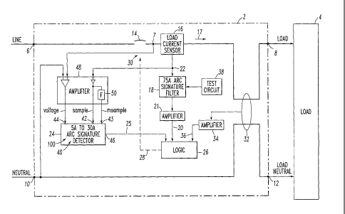
Referring to Figure 3, an arc fault circuit interrupter, such as circuit
breaker 2, is for an electrical circuit associated with one of a plurality of
different
types of loads, such as load 4. The circuit breaker 2 includes a line terminal
6 and
a load terminal 8. If the circuit breaker is optionally structured to provide
ground
fault protection, then it also includes a neutral terminal 10 and a load
neutral
terminal 12. As is conventional, separable contacts 14 are electrically
connected
between the line terminal 6 and the load terminal 8. A load current sensor 16
is
structured to sense current 17 flowing between the line and load terminals 6,8
and
through the separable contacts 14. Here, the current 17 is associated with one
of
the different types of loads and includes a plurality of alternating current
line
cycles. As is also conventional, a first arc fault detection circuit 18 (e.g.,
a 75 A arc
signature filter) is structured to generate a first trip signal 20 through
amplifier 21
responsive to the sensed current 22 from the current sensor 16. Suitable arc
fault
detection circuits, such as the circuit 18, are disclosed, for example, in
U.S. Patent
Nos. 5,224,006; 5,691,869; and 5,818,237.
CA 02625772 2008-04-09
WO 2007/045976 PCT/1B2006/002923
- 9 -
In accordance with the present invention, a second arc fault detection
circuit 24 (e.g., 5A to 30A arc signature detector) is structured to collect a
plurality of
samples of the sensed current 22 for a current one of the line cycles and a
plurality of
samples of the sensed current 22 for one of the line cycles prior to the
current one of
the line cycles, and to determine a total current value from a peak current of
the
samples of the sensed current for the current one of the line cycles. Although
not
required, the circuit 24 may preferably employ the total current value and
some of the
samples to determine the one of the types of loads, and may generate a second
trip
signal 25 responsive to the sensed current 22 and the determined one of the
types of
loads. A trip circuit 26 is structured to generate a third trip signal 28
responsive to the
first and second trip signals 20,25. An operating mechanism 30 is structured
to open
the separable contacts 14 responsive to the third trip signal 28.
Although not required, the circuit breaker 2 may include a ground fault
current sensor 32 (e.g., personnel protection; equipment protection; 30 mA)
and a
corresponding amplifier 34, which generates a ground fault trip signal 36 to
the trip
circuit 26. As is also not required, the first arc fault detection circuit 18
includes a
suitable test circuit 38, which generates the first trip signal 20 in response
to a user
request.
The second arc fault detection circuit 24 may be, for example, a
suitable PIC model microprocessor ( 13) as marketed by Microchip Technology
Inc.
of Chandler, Arizona, including, for example, internal memory for a suitable
firmware
routine 40, plural analog inputs, such as 42,43,44, and plural I/O lines, such
as output
46. Upstream of the second arc fault detection circuit 24 is a suitable
amplifier circuit
48, which buffers the analog sensed current 22 from the load current sensor 16
to the
first analog input 42 (sample), which buffers and filters the analog sensed
current 22
from the load current sensor 16 to the second analog input 43 (msample), and
which
buffers the switched line voltage 7 from the load side of the separable
contacts 14 to
the third analog input 44 (voltage). Preferably, the amplifier circuit 48
includes a
filter circuit (F) 50, which is a low pass circuit having a cutoff frequency
of about 1
kHz for the second analog input 43.
Figures 4A-4B show the clearing time algorithm 40 for the processor
24 of Figure 3. This algorithm 40 is suitable for arc faults resulting from
opposing
CA 02625772 2008-04-09
WO 2007/045976 PCT/1B2006/002923
- 10 -
electrodes (not shown) of a carbonized path arc clearing time test. First, at
52, the
algorithm 40 initializes the processor 24 of Figure 3, before it clears, at
54, current
sample arrays 56,56m,58,58m. Next, at 60, the algorithm 40 copies the values
from
the current arrays 56,56m to the previous arrays 58,58m, respectively. Then,
the
algorithm 40 collects the two current sets of the current samples in the
arrays 56
(sample), 56m (msample) from the respective analog inputs 42,43 of Figure 3.
In this
example, a count (e.g., x+1) of the samples of the sensed current for a
current one of
the line cycles is about 19 (e.g., sample #0 (or sample (0)) through and
including
sample #18 (or sample (18)). The line cycles, such as 61, include a positive
half cycle
61P and a negative half cycle 61N. Preferably, the algorithm 40 collects the
samples
of the sensed current for the current one of the line cycles substantially
during the
positive half cycle 61P and during the start of the negative half cycle 61N,
and
processes the samples of the sensed current for the current one of the line
cycles, in
order to generate the second trip signal 25 (Figure 3) during the negative
half cycle
61N. In this example, the line voltage and the sensed current are in phase,
and the
algorithm 40 collects about 19 of the samples of the sensed current for the
current one
of the line cycles at a rate of about 32 samples per line cycle.
Alternatively, the
sensed current may lead or lag the line voltage. The algorithm 40 collects a
first one
of the samples (sample #0) of the sensed current at about the positive zero
crossing
61PZ of the line cycle of the line voltage, as sensed from analog input 44
(voltage)
(Figure 3). For example, the processor 24 employs an edge-triggered interrupt
(not
shown) that responds to the positive zero crossing 61PZ.
For example, if N is an integer, such as 8, then the algorithm 40
collects about 2N plus three (=19) of the samples of the sensed current for
the current
one of the line cycles. The algorithm 40 collects an (N+1)th one (e.g., 9th)
(e.g.,
sample #8) of the samples of the sensed current at about the positive peak of
the
positive half cycle 61P of the line voltage. The capacitive di/dt is maximum
(positive) at the line voltage positive peak, while resistive di/dt is zero.
The algorithm
collects a (2N+1)th one (e.g. 17th) (e.g., sample #16) of the samples of the
sensed
current at about the negative zero crossing 61NZ of the line cycle of the line
voltage.
In this example, two additional samples (e.g., sample #17 and sample #18) are
collected during the negative half cycle 61N.
CA 02625772 2008-04-09
WO 2007/045976 PCT/1B2006/002923
- 11 -
Although the processor 24 of Figure 3 inputs, converts and stores the
values substantially during the positive half cycle 61P plus a relatively
small portion
of negative half cycle 61N, with subsequent processing in the subsequent
portion of
negative half cycle 61N, this could be reversed. The processor 24 provides a
suitable
analog-to-digital conversion (e.g., without limitation, about 7 counts per
ampere) of
the sensed current values 22 (Figure 3) to the digital values in the arrays,
such as 56.
Next, at 62, the algorithm 40 determines a total current value (Ipeak)
63, which is the peak or maximum current of the first seventeen values of the
current
array 56. If the total current value is greater than 45 A, then, at 64, a trip
tally 65 is
cleared, since the current samples in the array 56 do not represent a low
level arc.
After step 64, execution resumes at 76. Otherwise, if the total current value
is less
than 45 A, then execution resumes with the test at 66. If any of the tests at
even steps
66-74 fail, then, again, the current samples in the array 56 do not represent
an arc and
execution resumes at 76. However, if all of the tests at even steps 66-74
pass, then the
current samples in the array 56 do represent an arc and execution resumes at
78.
At 66, it is determined if any of the first seventeen current samples in
the current array 56 are greater than 1 A. If so, then at 67, a value, Ix, is
determined
to be the larger of Ipeak/8 or 0.5 A. Next, at 68, it is determined if the
sixteenth and
seventeenth samples in the current array 56 are both less than Ix. If so, then
at 70, it is
determined if either the fourteenth or the fifteenth samples in the current
array 56 are
greater than Ix. If not, then the load is a computer; but, if so, then at 72,
it is
determined if the second sample in the current array 56 is less than one half
of Ix. If
so, then at 74, it is determined if the eighth sample less the tenth sample in
the current
array 56 is less than one sixteenth of Ipeak. If not, then there is a
capacitive load. On
the other hand, since all of even tests 66-74 have passed, then the load is an
arc and
execution resumes at 78.
If there was no arc, then step 76 decrements the trip tally 65 by one,
unless such trip tally was already zero. Hence, the trip tally 65 is greater
than or equal
to zero. Otherwise, if there was an arc, then, step 78 adds the total current
value
(Ipeak) 63, which is the peak or maximum current of the first seventeen values
of the
current array 56, to the trip tally 65.
CA 02625772 2008-04-09
WO 2007/045976 PCT/1B2006/002923
- 12 -
After either of the steps 76,78, at 80, it is determined if the trip tally 65
is greater than a suitable threshold (e.g., 60) or if a TRIP_flag 81 (routine
86) was set.
If so, then, at 82, the circuit breaker 2 of Figure 3 is tripped by asserting
the second
trip signal 25 (Figure 3), after which the processor 24 awaits power down,
since the
separable contacts 14 (Figure 3) and the source of power (not shown) therefrom
is to
be removed. On the other hand, if the trip tally 65 is not greater than its
threshold
(e.g., 60) and if the TRIP_flag 81 was not set, then three routines 84, 86 and
88 are
sequentially executed before execution resumes at 60. Routine 84 provides a
zip cord
clearing time algorithm. Routine 86 provides a differential loads masking
test.
Routine 88 provides a compressor masking detection (di/dt) algorithm.
Referring to Figure 12, a routine 100 to enable or disable series arc
protection is executed by the processor 24 of Figure 3. A current inrush
detector 102
looks for a suitable predetermined (e.g., without limitation, a 10 ApEAK)
increase of
the sensed current in the array 56 (sample) from cycle to cycle. If such an
increase
occurs, then a current inrush detector flag (inrush_flag) 104 is set to a
predetermined
count (e.g., without limitation, 20) and a chaos detector flag (chaos_flag)
106 is
incremented by a predetermined count (e.g., without limitation, 10). As will
be
discussed, the routine 100 decrements these counts once per cycle until they
respectively reach a value of zero. By employing, for example, about a 10
ApEAK
increase in peak current, the current inrush detector 102 and the current
chaos detector
are fairly immune to changes in current resulting from series arcs, which
typically
cause amplitude variations that are much less.
For example, during a given cycle, if the current inrush detector flag
104 is zero, then the load current is considered to be in steady-state and,
hence, series
arc fault detection is enabled. However, if the current inrush detector flag
104 is
nonzero and the current chaos detector flag 106 is less than, for example,
about 10,
then a single current transient is assumed to have occurred and the series arc
fault
detection is disabled. Also, if the current inrush detector flag 104 is
nonzero and the
current chaos detector flag 106 is greater than, for example, about 10, then
multiple
current transients are assumed to have occurred. Since the load current might
be
indicative of a dangerous condition, series arc fault detection is enabled.
CA 02625772 2008-04-09
WO 2007/045976 PCT/1B2006/002923
- 13 -
The routine 100 and the various arc fault algorithms disclosed by
United States Patent Application Serial No. 10/895,158 may preferably work in
tandem to prevent nuisance tripping whenever there are relatively high inrush
current
transients.
The operation of the routine 100 is shown, by example, for a step
application of an individual load in parallel with a steady-state load. The
routine 100
detects a current transient and disables series arc detection as will be
discussed further
in connection with Figure 12. Figure 5 shows operation of the routine 100
during a
step application of an example 60 Hz, 120 V voltage source to a computer (not
shown) with rectifier/capacitor input characteristics. Figure 5 plots the
resulting load
current 108, the current inrush detector flag 104, the current chaos detector
flag 106
and a series arc protection enable flag 110 (which is the logical inversion of
the
series_arc_protection_inhibit signal 112 of Figure 12) versus time for current
inrush
detector operation of the arc fault circuit interrupter 2 of Figure 3. Here,
there is one
example chaos event after which the current chaos detector flag 106 returns to
zero
after 10 cycles, and the current inrush detector flag 104 returns to zero
after 20 cycles
during which time series arc protection is not enabled.
In Figures 6-8, the operation of the routine 100 of Figure 12 is
presented by a number of example step applications of individual loads in
parallel
with steady-state loads, which result in load currents 114 (10 ARms resistive
load in
parallel with step application of computers with rectifier/capacitor input
characteristics), 116 (5 ARMS resistive load in parallel with step application
of 3/4 HP
electric motor with no mechanical load), 118 (1000 W of dimmer-controlled
incandescent lighting in parallel with step application of a vacuum sweeper),
respectively. In each case, the routine 100 detects one current transient and
disables
series arc detection. These examples are important for practical situations,
for
example, where it is typical for a single (e.g., 15 A or 20 A) circuit breaker
to supply
several different loads, any of which may turn on at any given time.
In Figures 9-11, the operation of the routine 100 of Figure 12 is
presented, by example, for a number of compressor loads in parallel with
steady-state
loads, which result in load currents 120 (compressor experiencing series
arcing), 122
(5 ARMS resistive load with no arcing, in parallel with a compressor
experiencing
CA 02625772 2008-04-09
WO 2007/045976 PCT/1B2006/002923
- 14 -
series arcing), 124 (1000 W of dimmer-controlled incandescent lighting with no
arcing, in parallel with a compressor experiencing series arcing),
respectively.
Generally, when an arc occurs in series with a compressor, the compressor
current
alternately quenches and re-strikes several times. Each time a re-strike
occurs, the
compressor draws a relatively high inrush current that rapidly decays.
However, it is
important to ensure that the routine 100 does not disable series arc detection
following
each re-strike. Thus, if several current transients occur within a relatively
short
interval of time, the routine 100 re-enables series arc detection.
Returning to Figure 12, initialization of the routine 100 (which is
executed at startup prior to the routine 100) occurs at even steps 130-134.
The routine
100, beginning at 136, is executed once per electrical line cycle. Step
voltages (e.g.,
applying a 60 Hz 120 VRms source to a load) can cause major variations in load
current, although series arcs tend to cause only minor variations in load
current. The
routine 100 detects variations in load current based on sudden load current
increases
and inhibits series arc protection (and thereby nuisance tripping) until the
load has
reached steady-state. However, if several load current increases occur in
rapid
succession, then the routine 100 re-enables series arc protection.
During initialization of the routine 100, the inrush_flag 104 and the
chaos_flag 106 are both set to zero, and the series_arc_protection_inhibit 112
signal is
set false. During the routine 100, after beginning at 136, it is determined,
at 138, if
the inrush_flag 104 is greater than zero. If so, then the inrush_flag 104 is
decremented at 140. Otherwise, or after 140, it is determined if the
chaos_flag 106 is
greater than zero at 142. If so, then the chaos_flag 106 is decremented at
144.
Otherwise, or after 142, it is determined if the difference between the
peak_current
(Ipeak 63 from the array 56) and the previous_peak_current (from the array 58)
is
greater than a predetermined value (e.g., without limitation, 10 A). If so,
then, at 146,
the inrush_flag 104 is set to a first predetermined value (e.g., without
limitation, 20)
and the chaos_flag 106 is incremented by a second predetermined value (e.g.,
without
limitation, 10). Otherwise, or after 146, at 148, it is determined if the
inrush_flag 104
is zero, or if the inrush_flag 104 is greater than zero and the chaos_flag 106
is greater
than 10. If so, then at 150, series arc protection is enabled by setting false
series_arc_protection inhibit 112. On the other hand, if the test at 148 is
false, then at
CA 02625772 2013-05-14
- 15 -
152, series arc protection is disabled by setting true
series_arc_protection_inhibit
112. After either 150 or 152, the routine 100 completes, at 154, for the
current line
cycle until it re-starts, at 136, for the next line cycle.
Step voltages (such as, for example, applying a 60 Hz, 120 VRms
source to a load) can cause major variations in load current, while series
arcs tend
to cause only minor variations in load current. The disclosed routine 100
detects
variations in load current based on sudden load current increases and inhibits
series arc protection (and thereby nuisance tripping) until the load has
reached
steady-state. However, if several (e.g., without limitation, two or more) load
current increases occur in relatively rapid succession, then the routine 100
re-
enables series arc protection.
Although the example arc fault detection circuit 24 employs a
microprocessor, it will be appreciated that a combination of one or more of
analog,
digital and/or processor-based circuits may be employed.