Note: Descriptions are shown in the official language in which they were submitted.
CA 02626090 2008-04-15
WO 2007/033989 PCT/EP2006/066628
Mixing device and method for adding an additive to a
pumpable mixture
Technical field
The invention is based on a mixing device according to
the precharacterizing clause of the first claim.
The invention is likewise based on a method for adding
an additive to a pumpable mixture according to the
precharacterizing clause of the independent method
claim.
Prior art
In many applications, small amounts of a substance, for
example an additive, are admixed to a mixture with
plastic-viscous behavior. However, thoroughly good
mixing is frequently difficult to achieve. For example,
to mix an additive, for example an activator, with fine
mortar, use is made of conventionally known static
mixers. If such known static mixers are also used with
conventional concrete, the static mixer rapidly becomes
blocked because of the coarse gravel fraction, and the
mixer may even be destroyed.
The addition of the activator to the truck-mixed
concrete and the mixing are therefore frequently
already undertaken in the vehicle drum. The activator
plasticizes the concrete and brings the setting
mechanism into motion. A disadvantage is that, after
the activator has been added to the concrete in the
vehicle drum, not much more time must elapse before the
activated concrete is used in the construction, since
it otherwise already hardens beforehand.
Summary of the invention
The invention is based on the object, in the case of a
mixing device and a method of the type mentioned at the
CA 02626090 2008-04-15
WO 2007/033989 - 2 - PCT/EP2006/066628
beginning, of providing a mixing device which makes it
possible to rapidly and efficiently introduce additive
to a plastic-viscous mixture.
This object is achieved according to the invention by
the features of the first claim.
It is therefore the core of the invention that the
mixing device comprises a diffuser element and a
confusor element, and that at least one metering
apparatus with at least one metering location, by means
of which additive is added to the mixture, is arranged
in the interior of the mixing device.
The advantages of the invention include the fact that
the device shown here and the method are suitable in
particular for the continuous addition and mixing of
very small amounts of chemical additive to a pumpable
mixture with plastic-viscous behavior, in particular to
a granule-suspension mixture, such as concrete.
The invention therefore relates to a mixing apparatus
for the continuous, homogeneous addition of very small
amounts of chemical liquid additives to a pumpable
granule-suspension mixture which has a plastic-viscous
behavior, in particular wet concrete or truck-mixed
concrete, such that said concrete can harden/set
uniformly and in a defined manner, since, in particular
in the case of concrete, an activator is used as the
additive.
The practical difficulty of the realization in terms of
apparatus of such a project resides in the homogeneous
distribution of extremely small amounts of additive and
in the blockage-free conveying, for example of the
concrete, through the mixing apparatus. In more precise
terms, there is both a general risk of blockage as the
concrete flows around the metering elements and also as
it flows from the cylindrical part of the mixing
CA 02626090 2008-04-15
WO 2007/033989 - 3 - PCT/EP2006/066628
apparatus into the convergent part, and also local
backflows in the mixing device and therefore nonuniform
residence times, which results in different chemical
reaction times in the granule-suspension mixture. The
inert gravel fraction can be understood as meaning the
granule, and fine sand, cement and water can be
understood as meaning the suspension of the mixture
fraction.
According to the invention, the additive is added via
one or more metering apparatuses, for example helical
coils, with the shape of the metering apparatus and a
number of metering locations being designed and
dimensioned in respect of a locally uniform and
continuous distribution of the additive. This means,
inter alia, that the flow of the granule-suspension
mixture, for example of the concrete, is at the same
time less obstructed, and therefore no blockage occurs.
Furthermore, the effect achieved by the high solids
fraction of, for example, gravel in the ready-mixed
concrete is that the liquid amount of additive which is
metered in only passes into the suspension fraction of
the concrete.
Further advantageous refinements of the invention
emerge from the subclaims.
Brief description of the drawing
Exemplary embodiments of the invention are explained in
more detail below with reference to the drawings.
Identical elements are provided with the same reference
numbers in the various figures. The direction of flow
of the media is indicated by arrows.
In the drawings:
Figure 1 shows, schematically, the use of concrete in
a construction;
CA 02626090 2008-04-15
WO 2007/033989 - 4 - PCT/EP2006/066628
Figure 2 shows a schematic illustration of the outer
shape of the mixing device according to the
invention;
Figure 3 shows a schematic illustration of the outer
shape of a further mixing device according to
the invention;
Figure 4 shows a schematic illustration of the mixing
device according to the invention according
to figure 2 with a metering-in apparatus;
Figure 5 shows a schematic illustration of the mixing
device according to the invention according
to figure 2 with a further metering-in
apparatus;
Figure 6 shows a schematic side view of the mixing
device according to the invention according
to figure 2 with a further metering-in
apparatus;
Figure 7 shows a schematic top view along the axis of
the metering-in apparatus;
Figure 8 shows a schematic top view along the axis of
the metering-in apparatus in the mixing
device with the granule-suspension mixture;
Figure 9 shows a schematic illustration of the
metering-in operation;
Figure 10 shows a schematic illustration of a mixing
device according to the invention with a
further metering-in apparatus;
Figure 11 shows a schematic illustration of a mixing
device according to the invention with a
further metering-in apparatus;
Figure 12 shows a schematic illustration of the
geometry of the confusor;
Figure 13 shows a schematic illustration of the
geometry of the confusor;
Figure 14 shows a schematic illustration of the
geometry of the diffuser.
Only the elements essential for directly understanding
the invention are shown.
CA 02626090 2008-04-15
WO 2007/033989 - 5 - PCT/EP2006/066628
Way of implementing the invention
Figure 1 illustrates, schematically, the use of a
plastic-viscous mixture, here of concrete 10, in a
construction. Concrete is delivered to the building
site by means of a transport vehicle 1. The fact that
the concrete is usually transported in a rotating drum
mounted on the transport vehicle is not illustrated.
This concrete has been treated in the concrete factory
with additives such that the hydration or setting
mechanism is delayed by a number of hours. This
concrete corresponds in general to a pumpable granule-
suspension mixture with plastic-viscous behavior. The
concrete 10 is temporarily stored in a container 2 or
else is pumped directly from the vehicle to the
building site under pressure by means of a pump 3 and a
line 4. Such a line may be used for transporting the
concrete over several hundred meters or even a few
kilometers. Before the concrete 10 is used, the latter
has to be reactivated for use by the addition of
additives 5, such as activators, for example a setting
accelerator. The addition of the additive takes place
in a mixing device 6. Further substances, for example
water, concrete from a different source, etc., can be
supplied via a further line 7. The concrete 10' which
is mixed with the additive 5 is then appropriately used
at the building site at the use location 20. The
concrete can be used in accordance with any desired
methods, for example by means of spraying methods,
casting methods, etc. The distance of the mixing device
to the use location is as desired per se, but is
advantageously selected to be as short as possible such
that as little waste as possible occurs nor does
activated concrete remain in the line and possibly make
the latter unusable. With the present mixing device, it
is also possible to fill the line from the mixing
device to the use location with non-activated concrete
10 by no more activator being added to the mixing
CA 02626090 2008-04-15
WO 2007/033989 - 6 - PCT/EP2006/066628
device. This prevents the line from becoming blocked.
By means of the mixing device shown here, it is
permitted to meter in and mix small amounts of additive
with the plastic-viscous mixture, in particular in a
ratio of 1:100 to 1:1000.
Figures 2 and 3 illustrate the mixing device 6
schematically. Said mixing device comprises a diffuser
element 8, a cylinder element 9 and a confusor element
11 in the direction of flow of the granule-suspension
mixture. The cylinder element 9 may have any desired
cross section, such as circular, oval, polygonal, etc.,
and the cross sections are in each case adapted to the
particular requirements. The length of the cylinder
element 9 is likewise adapted in each case to the
particular conditions, such as amount of additive to be
added, etc., and may, according to figure 2, be
virtually zero. The diameter of the cross section
remains essentially constant in the cylinder element.
The diffuser element is divergent and has an expansion
angle a. The expansion angle a of the divergent part of
the mixer apparatus is necessitated by the flow or
depends on the permissible overall length of the mixing
apparatus. A backflow may occur in the vicinity of the
wall, see figure 14 in this respect, if the expansion
angle is too large and/or the viscosity of the medium
is too low. If the plastic-viscous flow of behavior of
concrete in a cylindrical line with an apparent dynamic
viscosity of ri = 30 Pa=s is described, then the classic
fluid dynamics presupposes a backflow after an
expansion angle a = approx. 60 , since Blasius's
equation for the flow in a diffuser is:
Redy_35
dl 2
where dy/dl = tan((XG). The following applies for the
expansion angle a:
CA 02626090 2008-04-15
WO 2007/033989 - 7 - PCT/EP2006/066628
- if a>aG, then a backflow occurs.
- if a<aG, then no backflow occurs.
The expansion angle a of the diffuser is therefore
preferably selected in a range of a = 10 to 60 , so
that no backflow occurs. Of course, this angle may vary
depending on the viscosity of the granule-suspension
mixture used, it being essential that no backflow takes
place.
The confusor element 11 is convergent and has a closing
angle R. Experience shows that, in particular, a rapid
reduction in diameter, i.e. a large angle R of concrete
transport lines, leads to blockage. The angle R is
preferably selected in a range of R= 5 to 20 .
There are essentially two types of outflow, the core
flow and the mass flow. The two types of outflow are
dependent on the closing angle, also called the cone
angle, and the outlet diameter. For example, there is a
core flow in a silo with a steep angle, i.e. the bulk
material in the center flow outs while the bulk
material at the wall temporarily remains stationary.
Such a behavior in the concrete line leads to a
blockage, since, for reasons of continuity, the
conveying by piston requires an outflow which is
constant over the entire cross section, i.e., in the
case of concrete, a flow velocity which is constant
over the cross section.
In the case of a shallow angle, the mass flow occurs.
This flow is constant over the cross section. Faced
with the requirement for a constant concrete flow
velocity, this means that the mass flow is the desired
flow form in the convergent part of the mixing
apparatus. The angle R is therefore preferably selected
in such a manner that a mass flow takes place.
CA 02626090 2008-04-15
WO 2007/033989 - 8 - PCT/EP2006/066628
There is a further risk of blockage due to bridging,
see figure 12. The cone geometry defined in the mixing
apparatus can now take place by means of criteria for
eliminating bridging. Among the demands made by said
criteria is that the angle 5 has to be > Y+gw because
the solids bridge then slides along the wall, i.e.
cannot get stuck, and consequently no blockage occurs
even in the case of plastic-viscous granule-suspension
mixtures, such as ready-mixed and truck-mixed concrete.
This gives rise, according to the invention, to the
angle y which defines the contour of the cone, see
figures 12 and 13. The wall friction angle gW is in each
case dependent on the material flowing through and on
the wall. Also according to figure 13, the convergent
part is advantageously defined by a convex and concave
radius. The convergent part can be welded together, for
example, from a dished head, basket head or any
spherical head and a"trumpet-shaped" confusor.
Stress peaks may occur during the transition between
the cylinder and cone. In the case of this mixing
apparatus according to the invention for the continuous
metering in of additive to the ready-mixed and truck-
mixed concrete, the stress peak is prevented by
specific, local-geometric design of the apparatus.
Depending on the concrete yield used, the diameter D is
advantageously in a range of D = 0.2 m to 0.75 m, and
the length 1 of the mixing device 6 is advantageously 1
= 0.8 m to 3 m.
The mixing device is in each case advantageously
arranged in a line with the concrete line, and
therefore it lies concentrically with respect to the
concrete line. As a result, pipe bends, angled
portions, etc. are no longer required, which saves on
space. The mixing device can be installed both
horizontally and vertically in the concrete conveying
line.
CA 02626090 2008-04-15
WO 2007/033989 - 9 - PCT/EP2006/066628
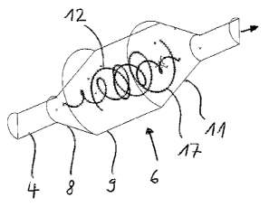
Figure 4 illustrates the mixing device 6 with a
metering apparatus 12. The metering apparatus 12 here
is a helical coil on which are arranged a plurality of
metering locations 13, which can also be referred to as
injection locations. The metering locations 13 are
advantageously arranged in the direction of flow of the
mixture 10 such that the additive is metered in the
direction of flow and the metering locations do not
become blocked. The additive can be added via one or
more of the metering apparatus 12, for example here the
helical coils, with the shape of the metering elements
and number of the metering locations 13 being designed
and dimensioned with respect to a locally uniform and
continuous distribution of the additive. This means,
inter alia, that at the same time the flow of the
granule-suspension mixture, for example of the
concrete, is less obstructed, and therefore no blockage
occurs. Furthermore, the effect achieved by the high
solids fraction of, for example, gravel, in the ready-
mixed concrete is that the liquid amount of additive
metered in only passes into the suspension fraction of
the concrete. Gravel particles are inert and if they
are situated immediately in front of a local metering
or injection location, they only deflect the additive
jet, see figure 9 in this respect, and distribute the
additive further.
The course 14 of the added additive through the mixer 6
is now explained by way of example by means of a
metering location 13. After being metered into the
granule-suspension mixture, the additive follows the
mixture as a type of additive thread. These additive
threads are illustrated as spots over the cross section
at the location 15. The granule-suspension mixture then
flows through the confusor 11 and, at the location 16,
the additives are again illustrated as spots. It can
clearly be seen that the additive threads lie very much
closer together because of the narrowing than at the
CA 02626090 2008-04-15
WO 2007/033989 - 10 - PCT/EP2006/066628
location 15 in the cylinder 9. Thoroughly good mixing
of the additive into the granule-suspension mixture or
the suspension fraction is thereby achieved. The number
of metering locations is advantageously n = 100 to 300,
the metering locations are at a distance 1 = 10 to
70 mm, and the diameter of the metering openings is d
0.4 to 1.5 mm.
Figures 5 and 6 illustrate the mixing device 6 with a
metering apparatus 12 and 17 which here comprises a
first helical coil 12 and a second helical coil 17.
Said helical coils are nested together in such a manner
that a homogenous distribution of the metering
locations 13 takes place in the projection in the
metering locations over the cross sectional surface of
the mixing apparatus, see figure 7 in this respect.
Figure 8 illustrates how often gravel particles can
arrive at metering locations. Gravel particles are
inert and if they are situated right in front of a
local metering or injection location, they only deflect
the additive jet, see figure 9 in this respect, and
distribute the additive further.
It is apparent from figure 6 that the helical coils are
at a minimum distance a from the wall of the mixing
device 6. As already discussed, a blockage can occur
both locally in the metering apparatuses 12, 17 of the
mixing apparatus 6, which is fitted into a concrete
transport pipeline, but also in the expanding diffuser
and re-contracting part of the confusor apparatus. In
terms of qualitative considerations, the conveying of
the concrete in the cylindrical part through the mixing
apparatus and around the metering elements is uniform
over the cross section. For the mixer apparatus, it is
particularly advantageous for the distance, firstly,
from the metering apparatuses to the wall of the mixing
device 6 not at any point to drop below the critical
size a > 3 x dparticler preferably a = 3 to 9 x dParticler
particularly preferably a = 3 to 7 x dParticlei in
CA 02626090 2008-04-15
WO 2007/033989 - 11 - PCT/EP2006/066628
particular a = 5 to 7 x dPartiole = However, given an
appropriate pitch of the metering apparatus, in
particular of the coil, it is also possible to bring
the latter to the outside. This is advantageous in
particular if a relatively large area has to be
supplied with additive.
Figure 10 illustrates a further possibility of
configuring a metering apparatus 18. The metering
apparatus here comprises pipes 19 which are angled and
are each arranged twisted with respect to the other
pipe in the mixing device. By means of this
arrangement, a homogeneous distribution of the additive
over the cross section is likewise made possible, as is
apparent from the projection at the location 21.
Figure 11 shows a further possibility of configuring a
metering apparatus 22. The metering apparatus here
comprises pipes 23 which are likewise angled and are
each arranged on a central pipe 24. The central pipe 24
is located essentially on the longitudinal axis of the
mixing device 6. The pipes 23 and therefore the
metering locations (not illustrated specifically) can
be supplied with additive by the central pipe 24. By
means of this arrangement, a homogeneous distribution
of the additive over the cross section is likewise made
possible.
The pipes 19 and 23 shown in figures 10 and 11
advantageously have an appropriate pitch in order to
avoid the above-described problems with blockages.
The liquid additive is advantageously pumped through
the metering apparatuses in such a manner that it flows
at the end of the metering apparatus back through a
line to the conveying pump. There is therefore a
circuit. As a result, a virtually uniform pressure loss
through the metering openings is obtained over the
entire length of the additive line and therefore a
CA 02626090 2008-04-15
WO 2007/033989 - 12 - PCT/EP2006/066628
uniform metering of the additive at every delivery
location.
At an internal diameter of the metering line of 17.3 mm
and a volumetric flow of 1 m3/h, the calculated
pressure loss due to wall friction and outlet is
approx. Ap = 0.06 bar depending on the outlet velocity.
The additive is supplied in such a manner that it has a
positive pressure in comparison to the granule-
suspension mixture. This permits the injection and at
the same time prevents the nozzle from becoming
blocked.
Of course, the invention is not restricted to the
exemplary embodiment shown and described. Instead of
the activator, use may be made of any desired additives
or other substances which are to be mixed into a
plastic-viscous mixture in relatively small amounts.
Also the plastic-viscous mixture to be used is as
desired per se. Mixing devices of this type, as have
been illustrated above, can therefore be used not only
for mixing additives into concrete but also wherever
something has to be admixed to a mixture with plastic-
viscous behavior. Fields of application therefore
reside in the construction industry, oil refining,
pyro-metallurgical addition in the extraction of metals
from ores, the alloying of metals, production of dough
goods, the introduction of additives to dough, for
example nuts to bread, the introduction of berries,
etc. to yogurt, processing of plastics, the emulsifying
of aromatic oils into various foodstuffs, the
preparation of honey, the chemical industry,
pharmaceutical industry, dyeing industry, etc. In
particular in the production of ceramics by means of
slip castings, the slips are transported to the
ceramics factory and a thixotropic agent is also added
to the slip prior to casting.
CA 02626090 2008-04-15
WO 2007/033989 - 13 - PCT/EP2006/066628
List of reference numbers
1 Transport vehicle
2 Container
3 Pump
4 Line
5 Additive/activator
6 Mixing device
7 Line
8 Diffuser element
9 Cylinder element
10 Concrete, delayed
10' Concrete, activated
11 Confusor element
12 Metering apparatus
13 Metering location
14 Additive course
15 Cross-sectional projection, additive
16 Cross-sectional projection, additive
17 Metering apparatus
18 Metering apparatus
19 Pipe
20 Use location
21 Cross-sectional projection, additive
22 Metering apparatus
23 Pipe
24 Central pipe