Note: Descriptions are shown in the official language in which they were submitted.
CA 02626566 2013-12-04
-1-
Method and device for shrinking a heat shrink film
placed around a stack of items
The invention relates to a method for shrinking a heat
shrink film wrapping placed around a stack of items, in
particular a palleted stack of items, with at least one
shrinking device, which can be made to move in a
vertical direction on a frame, is formed in particular
as a shrink frame and is intended for shrinking the
heat shrink film wrapping by heating, wherein the heat
shrink film wrapping protrudes on the upper side at
least beyond the upper edge of the stack of items for
the upper shrink formation and arranged on the upper
side of the stack of items is a top sheet film, which
preferably protrudes beyond the edge of the stack of
items and is welded to the heat shrink film wrapping.
Such methods are used, for example, in the papermaking
industry. =Here, pallets with formats of different
dimensions that have to be packed on a shrink packing
line are used. The shrinking takes place in this case
after placing the top sheet film onto the upper side of
the stack of items and subsequently providing the heat
shrink film wrapping. The overhanging ends or edges of
the top sheet film and a bottom film that is possibly
additionally provided between the pallet and the stack
of items are in this case clamped in between the heat
shrink film wrapping and the stack of items or the
pallet. To
prevent ingress of moisture, adequate
climatic protection must be ensured. This is only the
case if adequate welding is ensured between the top
sheet film placed on the stack of items and the heat
shrink film wrapping formed as a sleeve.
The object of the invention is to provide a method by
means of which the aforementioned disadvantages can be
= avoided and which ensures adequate climatic protection
CA 02626566 2008-04-18
WO 2007/048558
PCT/EP2006/010198
- 2 -
by improved welding of the top sheet film and the
overhang of the heat shrink film wrapping.
This object is achieved by providing that, in a first
step, the hot gases rising up along the sides of the
stack of items are diverted inward, in a direction
extending at least approximately parallel to the upper
side of the stack of items, by a combined heat
diverting and pressing device, which is arranged above
the stack of items and is intended for preheating and
inwardly folding over the overhang of the heat shrink
film wrapping and for preheating the top sheet film in
the region of the upper side of the stack of items,
and, in a second step, the layers of the overhang of
the heat shrink film wrapping and of the top sheet film
that are now lying one on top of the other are joined,
at least in the region of the upper side of the stack
of items, by pressing the not yet completely cooled
layers lying one on top of the other of the heat shrink
film wrapping and the top sheet film onto one another
by means of the combined heat diverting and pressing
device.
By the method according to the invention, the hot gases
that normally rise up quickly are directed by the
combined heat diverting and pressing device over the
surface of the stack of items toward the middle, so
that even during the shrink-wrapping of the sides of
the stack of items during the upward movement of the
shrinking device, a preheating of the top sheet film in
the region of the upper side and a preheating of the
overhang of the heat shrink film wrapping take place.
At the same time, the overhang is folded over inward.
Furthermore, by the combined heat diverting and
pressing device, the not yet completely cooled layers
of the heat shrink film wrapping and the top sheet film
that are lying one on top of the other are joined by
CA 02626566 2008-04-18
WO 2007/048558
PCT/EP2006/010198
- 3 -
pressing them onto one another. =The pressure exerted
while they are pressed onto one another can be varied.
As a result, particularly good welding of the layers
lying one on top of the other is achieved, and
consequently very good climatic protection.
The top sheet film is in this case at least large
enough that, after folding over the overhang, a
peripheral contact between the laid-flat overhang of
the heat shrink film wrapping and the top sheet film is
ensured. Preferably, the top sheet film is larger than
the stack of items, so that the top sheet film is
folded down on all sides.
It goes without saying that the heat shrink film
wrapping may also protrude on the underside beyond the
lower edge of the stack of items to carry out a lower
shrink wrap. If
underside sealing of the stack of
items is also desired, a bottom film that preferably
protrudes beyond the edge and is welded to the heat
shrink film wrapping when carrying out the lower shrink
wrap may also be provided.
For shrinking, the shrinking device may initially be
made to move upward to carry out the upper shrink wrap
and subsequently made to move downward to carry out the
lower shrink wrap.
In the case of a special embodiment of the method, the
shrinking begins at approximately half the height of
the stack of items. The shrinking device is initially
made to move to half the height of the stack of items.
Then, the shrinking device is started and is initially
made to move vertically upward to carry out the upper
shrink wrap and, after that, is made to move vertically
downward to carry out the lower shrink wrap.
CA 02626566 2008-04-18
WO 2007/048558
PCT/EP2006/010198
- 4 -
In the case of a preferred embodiment of the method, it
is appropriate if, at least at the beginning of the
shrinking process, the overhang of the heat shrink film
wrapping that protrudes on the upper side beyond the
upper edge of the stack of items is made to stand up,
in particular by means of an air stream which is
generated by the combined heat diverting and pressing
device and is directed directly or indirectly outward.
In the case of such an embodiment, a fan may be
provided, for example, in the region of the combined
heat diverting and pressing device and be switched to
blowing for making the overhang stand up. The stream
impinging on the upper side is diverted outward and so
makes the overhang stand up. In the
rest of the
shrinking process, for example when carrying out the
upper shrinking wrap and the lower shrinking wrap, the
fan may be set to sucking.
The hot gases rising up along the sides of the stack of
items and diverted in a direction extending parallel to
the upper side of the stack of items can be sucked
away, in particular by means of the combined heat
diverting and pressing device. It goes without saying
that other configurations are also conceivable.
At least when the shrinking device is made to move
vertically downward, the layers of the heat shrink film
wrapping and of the top sheet film that are lying one
on top of the other are joined, at least in the region
of the upper side of the stack of items, by pressing
the not yet completely cooled layers lying one on top
of the other of the heat shrink film wrapping and the
top sheet film onto one another.
Alternatively, at least when carrying out the lower
shrinking wrap, the layers of the heat shrink film
wrapping and of the top sheet film that are lying one
on top of the other may be joined, at least in the
CA 02626566 2008-04-18
WO 2007/048558
PCT/EP2006/010198
- 5 -
region of the upper side of the stack of items, by
pressing the not yet completely cooled layers lying one
on top of the other of the heat shrink film wrapping
and the top sheet film onto one another.
The invention also relates to a device for shrinking a
heat shrink film wrapping placed around a stack of
items, in particular a palleted stack of items, with at
least one shrinking device, which can be made to move
in a vertical direction on a frame, is formed in
particular as a shrink frame and is intended for
shrinking the heat shrink film wrapping by heating,
wherein the heat shrink film wrapping protrudes on the
upper side at least beyond the upper edge of the stack
of items for the upper shrink formation and arranged on
the upper side of the stack of items is a top sheet
film, which preferably protrudes beyond the edge of the
stack of items and can be welded to the heat shrink
film wrapping.
Such devices are used, for example, in the papermaking
industry. Here,
pallets with formats of different
dimensions that have to be packed on a shrink packing
line are used. The shrinking takes place in this case
after placing the top sheet film onto the upper side of
the stack of items and subsequently providing the heat
shrink film wrapping. The overhanging ends or edges of
the top sheet film and a bottom film that is possibly
additionally provided between the pallet and the stack
of items are in this case clamped in between the heat
shrink film wrapping and the stack of items or the
pallet. To prevent ingress of moisture, adequate
climatic protection must be ensured. This is only the
case if adequate welding is ensured between the top
sheet film placed on the stack of items and the heat
shrink film wrapping formed as a sleeve.
CA 02626566 2008-04-18
WO 2007/048558
PCT/EP2006/010198
- 6 -
The object of the invention is to provide a device by
means of which the aforementioned disadvantages can be
avoided and which ensures shrink-wrapping with adequate
climatic protection by improved welding of the top
sheet film and the overhang of the heat shrink film
wrapping.
This object is achieved by arranging above the stack of
items a combined heat diverting and pressing device,
intended on the one hand for diverting the hot gases
rising up along the sides of the stack .of items in a
direction extending at least approximately parallel to
the upper side of the stack of items, for preheating
and inwardly folding over the overhang of the heat
shrink film wrapping and for preheating the top sheet
film in the region of the upper side of the stack of
items, and on the other hand for subsequently joining
the folded-over overhang of the heat shrink film
wrapping and of the top sheet film, at least in the
region of the upper side of the stack of items, by
pressing the not yet completely cooled layers lying one
on top of the other of the heat shrink film wrapping
and the top sheet film onto one another.
By the device according to the invention, the hot gases
that normally rise up quickly are directed by the
combined heat diverting and pressing device over the
surface of the stack of items toward the middle, so
that even during the shrink-wrapping of the sides of
the stack of items during the upward movement of the
shrinking device, a preheating of the top sheet film in
the region of the upper side and a preheating of the
overhang of the heat shrink film wrapping take place.
At the same time, the overhang is folded over inward.
Furthermore, by the combined heat diverting and
pressing device, the not yet completely cooled layers
of the heat shrink film wrapping and the top sheet film
CA 02626566 2008-04-18
WO 2007/048558
PCT/EP2006/010198
- 7 -
that are lying one on top of the other are joined by
pressing them onto one another. The pressure exerted
while they are pressed onto one another can be varied.
As a result, particularly good welding of the layers
lying one on top of the other, and consequently very
good climatic protection, are achieved.
The top sheet film is in this case at least large
enough that, after folding over the overhang, a
peripheral contact between the laid-flat overhang of
the heat shrink film wrapping and the top sheet .film is
ensured. Preferably, the top sheet film is larger than
the stack of items, so that the top sheet film is
folded down on all sides.
It goes without saying that the heat shrink film
wrapping may also protrude on the underside beyond the
lower edge of the stack of items to carry out a lower
shrink wrap. If
underside sealing of the stack of
items is also desired, a bottom film that preferably
protrudes beyond the edge and is welded to the heat
shrink film wrapping when carrying out the lower shrink
wrap may also be provided.
Preferably, a plate aligned parallel to the upper side
of the stack of items may be provided as the combined
heat diverting and pressing device.
At least the region of the combined heat diverting and
pressing device that can be brought into contact with
the upper side of the stack of items is made a little
smaller than the inside dimensions of the shrinking
device, to ensure that the shrinking device can be
allowed to move sufficiently during the upper shrink
wrap.
Preferably, the plate may have a coating, preferably a
Teflon coating, on the side facing the stack of items.
CA 02626566 2008-04-18
WO 2007/048558
PCT/EP2006/010198
- 8 -
The side edges of the combined heat diverting and
pressing device may be approximately in line with the
side edges of the stack of items. However, it is also
quite conceivable for the combined heat diverting and
pressing device to be a little smaller than the
dimensions of the stack of items. In such
a case,
suitable means for allowing a diversion of the hot
gases are provided.
Preferably, the combined heat diverting and pressing
device protrudes laterally beyond the contour of the
stack of items.
The combined heat diverting and pressing device may
have at least one clearance, preferably arranged
approximately in the middle of the combined heat
diverting and pressing device, for the upward exiting
of the hot gases flowing parallel to the upper side of
the stack of items in the direction of the middle.
Through the clearance, the diverted hot gases that flow
from the edge of the upper side in the direction of the
middle of the upper side are carried away upward. The
flow velocities thereby occurring also intensify the
folding over of the overhangs and the welding of the
overhang to the top sheet film. It goes without saying
that it is also possible for two clearances arranged
one behind the other to be provided, in particular in
the longitudinal extent of the combined heat diverting
and pressing device.
Preferably, the position of at least one clearance may
be variable, to change the point at which the hot gases
initially flowing parallel to the upper side of the
stack of items are diverted upward. An embodiment in
which the clearance is, for example, part of a covering
plate or a sliding plate that can be made to move in a
horizontal direction with respect to the heat diverting
CA 02626566 2008-04-18
WO 2007/048558
PCT/EP2006/010198
- 9 -
and pressing device, within a contour of an opening
provided in the each diverting and pressing device, is
conceivable.
Preferably, a transporting device for sucking away the
hot gases flowing parallel to the upper side of the
stack of items in the direction of the middle of the
stack of items may be provided over at least one
clearance. The transporting device has the effect that
a negative pressure is produced in the region of the
upper side of the stack of items, and consequently a
greater amount of hot gases is sucked into the region
between the upper side and the combined heat diverting
and pressing device and diverted. At
the same time,
the transporting device may also be used for blowing,
which serves for the possible initial standing up of
the overhang of the heat shrink film wrapping.
A reducing damper may be provided in the region of at
least one clearance. This
damper is in the closed
position during the placement of the combined heat
diverting and pressing device, and consequently when
the not yet completely cooled layers lying one on top
of the other of the heat shrink film wrapping and the
- 25 top sheet film are pressed onto one another. This
prevents the top sheet film from being drawn upward in
the region of the clearance by the thermal effect of
the hot air rising up from the heated surface of the
top sheet film. At the same time, the reducing damper
also allows the volumetric flow to be controlled during
the shrinking.
=
To prevent excessive heating of the combined heat
diverting and pressing device in cases of high pallet
capacities, at least the region of the combined heat
diverting and pressing device that can be brought into
contact with the not yet completely cooled layers lying
one on top of the other of the heat shrink film
CA 02626566 2008-04-18
WO 2007/048558
PCT/EP2006/010198
- 10 -
wrapping and the top sheet film may be coolable. For
example, a cooling system that is provided in the
region of the underside of the combined heat diverting
and pressing device and is cooled by water, air or some
other suitable cooling medium is conceivable.
If the device according to the invention is to be used
for packing stacks of items of different dimensions, it
is appropriate if, for adapting the distance between
the stack of items, on the one hand, and at least one
heating bar of the shrink frame, formed as a shrinking
device, that extends substantially parallel to the
corresponding side face of the stack of items, on the
other hand, at least one heating bar is variable in its
position by being made to move in a moving direction
aligned substantially orthogonally in relation to said
side face. This
adaptation ensures that the stack of
items is subjected to approximately the same heating
output in the region of all the side faces, in order
that a uniform shrinkage result is achieved.
If only an adaptation with respect to the length or the
width of the stack of items is desired, it is adequate
if only one heating bar is movable. Alternatively, the
two opposite heating bars of a shrink frame comprising
a total of four heating bars may be movable with
respect to each other. In the case of an adaptation to
the width and to the length of a stack of items, at
least two adjacent heating bars are movably formed.
Preferably, at least one of the two heating bars
extending substantially orthogonally in relation to the
transporting direction of the stack of items is
variable in its position by being made to move, to
adapt the distance between the stack of items on the
one hand and at least one of the heating bars extending
substantially orthogonally in relation to the
transporting direction of the stack of items.
CA 02626566 2008-04-18
WO 2007/048558
PCT/EP2006/010198
=
- 11 -
The heating bar that can be made to move in relation to
the remaining shrink frame may be arranged on at least
one rail, provided on the remaining shrink frame, and a
drive may be provided for making it move. The rail may
be attached either to the upper side or to the
underside of the shrink frame, the heating bar being
fastened to the rail by means of suitable measures. It
is also conceivable for the heating bar to have at both
its ends rollers which travel on a rail mounted on the
upper side of the shrink frame. A
kind of conveyor
belt that is led between two deflecting rollers and to
which the heating bar is fastened is also conceivable.
To ensure that the combined heat diverting and pressing
device has an approximately horizontal alignment, in
particular in the state in which it is lying against
the upper side of the stack of items, a device which
prevents tilting of the combined heat diverting and
pressing device, in particular in the state in which it
is lying against the upper side of the stack of items,
may be provided.
At least one heating bar may comprise a number of
heating segments, preferably a number of heating
segments that can be activated separately from one
another. In
the case of separate activation, the
heating segments can to this extent be switched on and
off separately.
Such an embodiment is appropriate,
since it is then possible to deactivate the heating
segments of the heating bars that are no longer acting
on the region enclosed by the movable heating bar(s)
and possibly by the non-movable heating bar(s) or part-
regions of it or them.
An exemplary embodiment of the invention that is
represented in the drawings is explained below. In the
drawing:
CA 02626566 2008-04-18
WO 2007/048558
PCT/EP2006/010198
- 12 -
Figure 1 shows a side view of a device according to
the invention with a shrink film and a
combined heat diverting and pressing
device,
Figures 2-7 show different positions of the shrink
film and the combined heat diverting and
pressing device,
Figure .B shows a plan view of the subject matter
that is shown in Figure 1
Figures 9-12 show side views of another embodiment of a
device according to the invention,
Figure 13 shows a plan view of the subject matter
that is shown in Figures 11 and 12 and
Figure 14 shows a plan view of the subject matter
that is shown in Figures 9 and 10.
In all the figures, the same reference numerals are
used for identical or similar components.
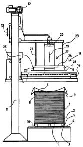
Figure 1 shows a side view of a device according to the
invention for shrinking a heat shrink film wrapping 2
placed around a stack of items 1. In the
exemplary
embodiment represented, the stack of items 1 is resting
on the underside on a pallet 3. The pallet 3 itself is
resting on a conveyor 4.
A bottom film 5 is initially placed on an empty pallet
3, the bottom film 5 protruding at the edges beyond the
pallet 3. The stack of items 1, for example paper, is
set down on the bottom film 5. Then, a top sheet film
6 is placed onto the stack of items 1 on the upper
side, the top sheet film 6 also protruding beyond the
CA 02626566 2008-04-18
WO 2007/048558
PCT/EP2006/010198
- 13 -
edge of the stack of items 1. The top sheet film 6 is
usually cut to length from a roll of continuous film.
Both the overhanging edge 7 of the bottom film 5 and
the overhanging edge 8 of the top sheet film 6 are
folded down.
In a further method step that is not represented, a
heat shrink film wrapping 2 is then placed around the
stack of items 1. For this purpose, the stack of items
1 may, for example, be moved against a film curtain
comprising a heat shrink film that extends transversely
in relation to the conveying direction. As it
runs
through, the heat shrink film comes to lie around the
stack of items 1. In the
region of the side facing
away from the moving direction, the heat shrink film
wrapping 2 placed in this way around the stack of items
1 is usually provided with a finishing weld by a
vertically aligned welding beam. In this way, a sleeve
is formed, such as that represented in Figure 1.
On the upper side and on the underside, the heat shrink
film wrapping 2 protrudes beyond the upper edge and the
lower edge, respectively, of the stack of items 1 to
form a respective overhang 9 and 10 for the later upper
=25 shrink formation and lower shrink formation. The
folded-over edges 8, 7 of the top sheet film 6 and of
the bottom film 5 are in this case located between the
heat shrink film wrapping 2 and the stack of items 1 or
the pallet 3.
Provided on a frame 11 alongside the conveyor 4 is a
shrink frame 14, which can be made to move in a
vertical direction (arrow 13) by means of a drive 12
and comprises four heating bars 14a for shrinking heat
shrink film wrapping by heating. At the same time, a
combined heat diverting and pressing device 15, which
can likewise be made to move in a vertical direction
(arrow 13) is provided on the frame 11. In the
CA 02626566 2008-04-18
WO 2007/048558
PCT/EP2006/010198
- 14 -
exemplary embodiment represented, this device comprises
a plate 16 aligned parallel to the upper side of the
stack of items 1, the plate 16 protruding beyond the
contour of the stack of items 1 by approximately 50 mm
on all sides in the exemplary embodiment represented.
On the side facing the stack of items 1, the plate 16
has a coating, for example a Teflon coating, to avoid
sticking to the top sheet film 6. Provided
in the
middle of the plate 16 in the case of the exemplary
embodiment represented in Figures 1 to 8 is a clearance
17 for the exiting of hot gases. This clearance 17 is
adjoined on the upper side by a channel portion 18, in
which a reducing damper 19 and a transporting device 20
formed as a fan are provided.
In Figure 8, the configuration of the combined heat
diverting and pressing device 15 is represented in
detail. As this
figure reveals, the combined heat
diverting and pressing device 15 is fastened to two
struts 21, which for their part are connected to the
frame 11. The struts 21 are fixed with respect to each
other by means of cross struts 22.
Provided on the struts 21 on the underside are holding
elements 23, which are formed as rods and at the lower
ends of which a four-cornered frame 24 is fastened. In
each corner, the frame 24 has an outwardly facing
holding plate 25, in each case with a bore 26.
As revealed by Figure 8 in conjunction with, for
example, Figure 4, the plate 16 of the combined heat
diverting and pressing device 15 is suspended at a
distance below the frame 24 to form a free space 27.
For this purpose, fastening pins 28 with a thickening
29 at the end are integrally formed on the upper side
of the plate 16. Each fastening pin 28 is guided in
CA 02626566 2008-04-18
WO 2007/048558
PCT/EP2006/010198
- 15 -
the associated bore 26, the thickening 29 being larger
than the diameter of the bore 26 and being located
above the holding plate 25.
When the plate 16 is in contact with the upper side of
the stack of items 1, the fastening pins 28 are
displaced in the bores 26, and the free space 27 is
thereby reduced. To make
such a displacement of the
plate 16 with respect to the frame 24 possible, the
channel portion 18 is also correspondingly formed. As
Figure 4 reveals, the channel portion 18 is subdivided
into a lower part-channel portion 18a with a smaller
contour and an upper part-channel portion 18b with a
larger contour, so that the two part-channel portions
18a, 18b are displaceable one inside the other.
The special configuration of the combined heat
diverting and pressing device 15 allows pressing only
to take place with the actual weight of the plate 16.
Only when the free space 27 has been overcome is it
possible to work with a higher pressing pressure, since
then the force of the drive 12 also acts in addition to
the weight of the remaining parts of the combined heat
diverting and pressing device 15.
The mode of operation according to Figures 1 to 7 is as
follows:
In Figure 1, the wrapped stack of items 1 is ready for
shrinking. The overhang 9 protruding upward beyond the
upper edge of the stack of items 1 is still undirected,
i.e. it is partially standing upright, partially folded
over outward or inward.
Then the shrink frame 14 moves into the position
represented in Figure 2, which corresponds to
approximately half the height of the stack of items 1.
Only when this position is reached is the shrink frame
CA 02626566 2008-04-18
WO 2007/048558
PCT/EP2006/010198
- 16 -
14, which is represented in section in Figures 2 to 7,
started. The hot gases flow upward in the direction of
the arrows 30 along the sides of the stack of items 1.
The transporting device 20 is in this case set to
blowing, so that air is blown in the direction of the
arrows 31 onto the upper side, and so the upper-side
overhang 9 is made to stand up. The reducing damper 19
is in this case in the open position.
During the moving up of the shrink frame 14, as
represented in Figure 3, the distance between the heat
diverting and pressing device 15 and the upper side of
the stack of items 1 is reduced. In
Figure 2, the
distance is approximately 500 mm. In
Figure 3, the
distance has been reduced to approximately 200 mm.
In the position represented in Figure 3, the
transporting device 20 has already been set to suction
removal, so that the hot gases flowing upward along the
sides (arrows 30) are diverted in a direction extending
parallel to the upper side of the stack of items 1
(arrows 32). In this
way, the heat shrink film
wrapping 2 and the top sheet film 6 in the region of
the upper side are also sufficiently heated for a good
upper shrink wrap.
In Figure 4, the shrink frame 14 has reached its
uppermost position. Then, the shrink frame 14 is made
to move vertically downward for shrink-wrapping the
sides, in particular in the lower region of the stack
of items 1, as represented in Figure 5. When it
is
being made to move vertically downward in this way, the
hot gases (arrows 32) continue as before to be sucked
away by means of the transporting device 20 through the
clearance 17, in the direction of the arrows 33.
In Figure 6, the shrink frame 14 has reached its
lowermost position to carry out the lower shrink
CA 02626566 2008-04-18
WO 2007/048558
PCT/EP2006/010198
- 17 -
formation. In the
position represented in Figure 6,
the transporting device 20 has been switched off and
the reducing damper 19 is closed. The
combined heat
diverting and pressing device 15 is pressed in the
direction of the arrow 34 onto the upper side of the
stack of items 1, so that the layers of the heat shrink
film wrapping 2 and of the top sheet film 6 that are
lying one on top of the other are joined to one another
in the region of the upper side by pressing the not yet
completely cooled layers lying one on top of the other.
It goes without saying that the pressing may also take
place at an earlier point in time.
After the shrinking process, the shrink frame 14 and
the heat diverting and pressing device 15 are displaced
again into the position represented in Figure 7, and
the wrapped and shrunk stack of items 1 is transported
away by means of the conveyor 4.
In Figures 9 to 14, a further exemplary embodiment of
the device according to the invention is shown. Here,
the heating bar 14a facing orthogonally in relation to
the transporting direction 35 is formed such that it
can be made to move with respect to the rest of the
shrink frame 14. This makes it possible to adapt the
distance between the stack of items 1 on the one hand
and the movable heating bar 14a of the shrink frame 14
formed as a shrink device. Being
allowed to move in
this way is appropriate if stacks of items 1 of
different dimensions, such as for example length, are
to be packed.
In Figures 9, 10 and 14, a stack of items 1 of a
relatively small length is represented. Therefore, the
left-hand heating bar 14a, represented in Figures 9 and
10, has been made to move in the direction of the
opposite heating bar 14a in a moving direction 36
CA 02626566 2008-04-18
WO 2007/048558
PCT/EP2006/010198
- 18 -
aligned substantially orthogonally in relation to the
side face.
In Figures 11, 12 and 13, the arrangement of the
heating bars 14a in the case of a stack of items 1 of a
relatively great length is represented. Here,
the
left-hand heating bar 14a has been made to move outward
almost completely.
In the exemplary embodiment of the invention
represented for example in Figures 10 and 11, the
heating bar 14a can be made to move into two different
positions. It goes
without saying that, to increase
adaptability, it is also possible to allow intermediate
positions of the movable heating bar 14a to be adopted.
To allow this movement, rails 37 are provided on the
upper side of the shrink frame 14. The heating bar 14a
is displaceably mounted on the two rails 37 by means of
guiding carriages 38. To make it move, a toothed belt
40 stretched between two deflecting rollers 39 acts on
the heating bar 14a. A dedicated drive for driving the
toothed belts 40 is not represented. The
deflecting
rollers 39 are fastened to the shrink frame 14 by means
of bearing brackets 39a. For a
better overview, the
toothed belt 40 is not depicted in Figures 13 and 14.
If the two heating bars 14a adjacent to the ends of the
movable heating bar 14a, along with the rails 37
arranged on the upper side, respectively comprise a
number of separately controllable, and to that extent
activatable, heating segments, it is advisable for the
heating segments in the region X of the heating bars
14a that protrudes at the end, along with the rails 37
attached on the upper side, to be deactivated in the
position of the heating bar 14a represented in Figure
10.
CA 02626566 2008-04-18
WO 2007/048558
PCT/EP2006/010198
- 19 -
In the position of the movable heating bar 14a
represented in Figure 11, all the heating segments of
the heating bars 14a, along with the rails 37 attached
on the upper side, are activated.
As can be seen from Figures 9 to 14, in the case of
this exemplary embodiment two clearances 17 are
provided in the plate 16 and are respectively adjoined
by a channel portion 18, in which a reducing damper 19
and a transporting device 20 formed as a fan are in
=each case provided.
In the case of the exemplary embodiment represented in
Figures 9 to 14, only one of the four heating bars 14a
is movably formed, while the rest of the shrink frame
14 comprising the other three heating bars 14a cannot
itself be made to move any further and assumes an
altogether U-shaped configuration. It goes
without
saying that embodiments in which two or more heating
bars 14a are movable are also possible, so that in this
way both adaptation to the length and adaptation to the
width of the stack of items 1 is possible.
In the case of the exemplary embodiment represented in
Figures 9, 10 and 14, the stack of items 1 is placed in
such a way that the middle of the stack of items 1
coincides approximately with the middle of the right-
hand clearance 17. In this
case, the distance on
opposite sides from the heating bars 14a that are
respectively adjacent and parallel to the sides is
approximately the same. If the
stack of items 1
represented in Figures 9 and 10 is concerned, the left-
hand heating bar 14a is then made to move in the
direction of the stack of items 1 until the distance
corresponds approximately to the distance between the
other three heating bars 14a and the stack of items 1.
CA 02626566 2008-04-18
WO 2007/048558 PCT/EP2006/010198
- 20 -
In the position of the heating bar 14a represented in
Figures 9, 10 and 14, the reducing damper 19 of the
channel portion 18 represented on the left in Figure 9
is closed. Consequently, in the later suction-removal
phase, the heating gases are only sucked away by means
of the transporting device 20 through =the right-hand
clearance 17, in the direction of the arrows 33.
In the case of stacks of items 1 of greater lengths, as
represented in Figures 11, 12 and 13, both transporting
devices 20 are "active" and, for example, both reducing
dampers 19 are open during the suction removal, since
both clearances 17 are located within the contour of
the stack of items 1. The stack of items 1 is in this
case placed in such a way that the middle between the
clearances 17 is aligned approximately to coincide with
the middle of the upper side of the stack of items 1.
The operating situation represented in Figure 12 for a
relatively long stack of items 1 and in Figure 10 for a
relatively short stack of items 1 corresponds
approximately to the operating situation represented in
Figure 2.
To prevent tilting of the combined heat diverting and
pressing device 5 in the state in which said device is
lying against the upper side of the stack of items 1,
in particular in the case of stacks of items 1 of
relatively small length, a device 41 is provided.
This device 41 is provided in the region of the edge of
the plate 16 that laterally protrudes the most with
respect to the stack of items in comparison with the
other edges of the plate 16.
In the exemplary embodiment represented, the device 41
is formed as a cylinder 42, which acts on a lever arm
43 connected to the plate 16, and so the plate 16 is
raised in the region of this edge. Consequently, the
CA 02626566 2008-04-18
WO 2007/048558
PCT/EP2006/010198
- 21 -
plate 16 does not tilt but is held in an approximately
horizontal alignment, so that approximately the same
force acts on every point of the upper side of the
stack of items 1.
If a number of heating bars 14a are movable, it is
appropriate if a device 41 is provided in the region of
every edge of the plate 16 where there is an adjacent
movable heating bar 14a.