Note: Descriptions are shown in the official language in which they were submitted.
CA 02626978 2008-03-26
SUPPORT DAMPERS FOR BEARING ASSEMBLIES AND METHODS OF
MANUFACTURE
TECHNICAL FIELD
[00011 The inventive subject matter relates to support dampers and, more
particularly, to support dampers for use in bearing assemblies.
BACKGROUND
100021 Gas turbine engines are used as the primary power source for many types
of aircraft. Most turbine engines include rotating components such as a fan, a
compressor, and a turbine. The rotating components may be clamped together
either
by a tieshaft or bolted flange joints to form a rotor group. Two or more
bearing
assemblies may be employed to support the rotor group. Generally, the bearing
assemblies may be surrounded by a support housing, which may be connected to
an
engine case.
[0003] During high-speed rotation of the rotor group, forces may be
transmitted
from the rotor group to the support housing. To damp the effects of the
transmitted
forces, a squeeze film damper may be included in some engines. A squeeze film
damper operates by supplying fluid (usually oil) through dedicated oil
delivery
passages into a squeeze film cavity formed via a clearance between the support
housing and the bearing assemblies.
[0004] Although squeeze film dampers are relatively useful in reducing rotor
vibration in some cases, they may suffer drawbacks in others. For example,
because
the rotor orbiting within the mount itself may become off-center with respect
to the
squeeze film cavity, the rotating rotor group may not remain concentric. Thus,
the
CA 02626978 2008-03-26
2
rotor may sit at the bottom of the damper clearance or may be unable to
precess
around the clearance between the bearing assembly and the support housing. As
a
result, the squeeze film damper may become relatively stiff during operation
and may
not absorb as much vibration as desired. Additionally, the support housing
stiffness
may allow the rotor group to vibrate with certain modes when subjected to a
particular
engine operating speed range, and the squeeze film damper may not adequately
damp
this increased rotor unbalance response.
(0005] Hence, it is desirable to have an apparatus that may be used to improve
the
damping capabilities of an off-center squeeze film damper and provide a
support
structure stiffness that minimizes a rotor-to-structure unbalance response. It
is
desirable for the apparatus to be capable of limiting rotor radial excursion
and to
accommodate a particular rotor thrust load. It is also desirable for the
apparatus to
have a relatively compact design and to be capable of being retrofitted into
existing
engines.
BRIEF SUNIlVIARY
(0006] The inventive subject matter provides a support damper for a bearing
assembly and methods of manufacturing the same.
(0007] In one embodiment, and by way of example only, the support damper
includes an inner ring, an outer ring, and a U-shaped beam. The inner ring is
configured to be disposed around the bearing assembly and to extend axially
along a
portion thereof. The outer ring is spaced apart from the inner ring and
extends
radially outwardly relative thereto. The U-shaped beam couples the inner ring
to the
outer ring.
[0008] In another embodiment, and by way of example only, a bearing damper
assembly includes a shaft, a bearing assembly, and a support damper. The
bearing
assembly is mounted to the shaft. The support damper is disposed around the
bearing
CA 02626978 2008-03-26
3
assembly and includes an inner ring, an outer ring, and a U-shaped beam. The
inner
ring is configured to be disposed around the bearing assembly and to extend
axially
along a portion thereof. The outer ring is spaced apart from the inner ring
and extends
radially outwardly relative thereto. The U-shaped beam couples the inner ring
to the
outer ring.
100091 In still another embodiment, and by way of example only, a method is
provided for manufacturing a support damper for disposal around a bearing
assembly.
The method includes forming an inner ring configured to be disposed around and
to
extend axially along a portion of the bearing assembly, forming an outer ring
configured to extend radially outwardly relative to the inner ring, and
coupling the
inner ring to the outer ring with a U-shaped beam.
100101 Other independent features and advantages of the preferred assemblies
and
methods will become apparent from the following detailed description, taken in
conjunction with the accompanying drawings which illustrate, by way of
example, the
principles of the inventive subject matter.
BRIEF DESCRIPTION OF THE DRAWINGS
[00111 FIG. 1 is a simplified, cross-sectional view of a gas turbine engine,
according to an embodiment;
[00121 FIG. 2 is a close-up view of an area between a fan section and a
compressor section of the engine indicated by a dotted line 2 shown in FIG. I
in
which a support damper is implemented, according to an embodiment;
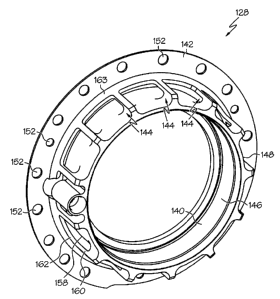
100131 FIG. 3 is a perspective view of a support damper, according to an
embodiment; and
CA 02626978 2008-03-26
4
100141 FIG. 4 is a close-up view of an area of the engine indicated by a
dotted line
4 shown in FIG. 2 of a transfer passage and transfer tube, according to an
embodiment.
DETAILED DESCRIPTION
100151 The following detailed description is merely exemplary in nature and is
not
intended to lirnit the inventive subject matter or the application and uses of
the
inventive subject matter. Although the inventive subject matter is described
as being
implemented between a fan section and compressor section of a gas turbine
engine,
the inventive subject matter may be used with other configurations in which
components are mounted to a rotor, or where the rotor may be capable of
exerting an
unwanted unbalance load upon a structure. Furthermore, there is no intention
to be
bound by any theory presented in the preceding background or the following
detailed
description.
[0016) FIG. I is a simplified, cross-sectional view of a gas turbine engine
100,
according to an embodiment. The engine 100 may be disposed in an engine case
101
and may include a fan section 102, a compressor section 104, a combustion
section
106, a turbine section 108, and an exhaust section 110. The fan section 102
may
include a fan 112, which draws air into the fan section 102 and accelerates
it. A
fraction of the accelerated air exhausted from the fan 112 is directed through
a bypass
section 103 to provide a forward thrust. The remaining fraction of air
exhausted from
the fan 112 is directed into the compressor section 104.
[0017] The compressor section 104 may include series of compressors 116, which
raise the pressure of the air directed into it from the fan 112. The
compressors 116
may direct the compressed air into the combustion section 106. In the
combustion
section 106, which includes an annular combustor 118, the high pressure air is
mixed
CA 02626978 2008-03-26
with fuel and combusted. The combusted air is then directed into the turbine
section
108.
[0018) The turbine section 108 may include a series of turbines 120, which may
be
disposed in axial flow series. The combusted air from the combustion section
106
expands through the turbines 120, causing them to rotate. The air is then
exhausted
through a propulsion nozzle 105 disposed in the exhaust section I 10,
providing
additional forward thrust. In an embodiment, the turbines 120 rotate to
thereby drive
equipment in the engine 100 via concentrically disposed shafts or spools.
Specifically, the turbines 120 may drive the compressor 116 via one or more
rotors
124.
100191 Tuming now to FIG. 2, a close-up view of an area between the fan
section
102 and the compressor section 104 indicated by a dotted line 2 shown in FIG.
1 is
provided, according to an embodiment. A bearing assembly 126, support damper
128, and squeeze film damper 130 are included to reduce vibration that may
occur
when the rotors 124 rotate. The bearing assembly 126 is disposed around a
portion of
the rotor 124 and maintains the rotor 124 in a desired position during
rotation. The
bearing assembly 126 includes an inner race 132, an outer race 134, and a
conventional rolling element 136, such as a ball or roller, disposed
therebetween. The
inner race 132 is mounted to the rotor 124.
[0020] The support damper 128 is configured to form a portion of the squeeze
film
damper 130 and is mounted to an annular support housing 138 (only a portion of
which is shown). Referring also to FIG. 3, which is a perspective view of the
support
damper 128, according to an embodiment, an inner ring 140, an outer ring 142,
and a
plurality of U-shaped beams 144 are included. The inner ring 140 extends
axially
along a portion of the bearing assembly 126 and includes an inner annular
surface 146
and an outer annular surface 148. In an embodiment, the inner annular surface
146
has a diameter that is sufficient to accommodate the bearing assembly 126, the
rotor
124, and the squeeze film damper 130. In another embodiment, the diameter of
the
CA 02626978 2008-03-26
6
inner annular surface 146 may also be sufficient to form a gap between the
support
damper 128 and the bearing assembly outer race 134 that forms the squeeze fihn
damper 130. In yet another embodiment, the inner annular surface 146 may be
formed to compensate for off-center characteristics that may exist in the
surrounding
components. For example, the rotor 124 may be off-center relative to the
support
damper 128, and the inner annular surface 146 may be formed such that its
center may
not be coincident with the center of the outer annular surface 148.
Alternatively, the
inner annular surface 146 of the support damper 128 or inner diameter of the
support
housing 138 with the engine structure 107 may be formed to compensate for off-
center characteristics that may exist in the surrounding components.
100211 The outer ring 142 is configured to mount the support damper 128 to the
support housing 138. In this regard, the outer ring 142 extends radially
outward
relative to the inner ring 140 and includes bolt openings 152 that accommodate
bolts
154 therein. In an embodiment, the outer ring 142 has an inner diameter that
may be
greater than an outer diameter of the inner ring 140.
[00221 To provide flexibility to the support damper 128, U-shaped beams 144
couple the inner and outer rings 140, 142 to each other. Each beam 144 may
include
a first arm 158 and a second arm 160. In an embodiment, the first arm 158
extends
along a portion of the inner ring outer annular surface 148, and the second
arm 160
includes an end 162 coupled to the outer ring 142. Although the second arm
ends 162
are shown as being integrally formed with an attachment ring 163, which may be
directly coupled to or formed with the outer ring 142, the second arm ends 162
may
alternatively be directly coupled to or formed with the outer ring 142.
Additionally,
although the second arm 160 is shown in FIG. 3 as being disposed substantially
perpendicular relative to the outer ring 142, in another embodiment, it may
not be.
100231 To limit radial displacement of the rotor 124, the U-shaped beams 144
may
be configured to maintain the inner and outer rings 140, 142 a predetermined
distance
apart from each other. In an embodiment, the inner ring outer annular surface
148
CA 02626978 2008-03-26
7
fonns a controlled clearance 109 with the support housing 138 to limit rotor
radial
displacement. In another embodiment, an axially extending section 164 of the
support
damper 128 may be used as a stop, and thus, the inner and outer rings 140, 142
are
held a sufficient distance apart to at least accommodate the thickness of the
axially
extending section 164. In still another embodiment, the U-shaped beam 144 may
be
configured to maintain the inner and outer rings 140, 142 a sufficient
distance apart
such that the axially extending section 164 contacts the outer ring 142
without
contacting the inner ring 140.
[0024] As mentioned briefly above, one or more U-shaped beams 144 may make up
a portion of the support damper 128. In an embodiment in which more than one U-
shaped beam 144 is included, the beams 144 may be symmetrically disposed
around
the inner and outer rings 140, 142 to thereby minimize rotor 124 excursion due
to
bearing thrust. In another embodiment, the U-shaped beam 144 may be
asymmetrically disposed around the inner and outer rings 140, 142. It will be
appreciated that the particular length of the beam arms 158, 160, the
particular cross-
section shape of the beams 144, and the particular number of beams 144
employed
may be varied, depending on a magnitude of excursion and vibration to which
the
rotor 124 may be subjected or the desired structural stiffness of the support
damper
128.
[0025] In another embodiment, the support damper 128 may be configured to
provide a path along which fluid may flow to the bearing assembly 126 and the
squeeze film damper 130. In this regard, the support damper 128 may include a
transfer passage 166 formed therein that is configured to accommodate a
transfer tube
168 that may be used to provide communication between the transfer passage 166
and
a fluid source passageway 170. Referring also to FIG. 4, which illustrates a
close up
view of an area indicated by a dotted line 4 shown in FIG. 2, in an
embodiment, the
transfer passage 166 may be formed between the inner ring inner and outer
annular
surfaces 146, 148 and disposed between two of the U-shaped beams 144. In
another
embodiment, the transfer passage 166 may be a separately formed component that
CA 02626978 2008-03-26
8
may be attached to the inner ring outer annular surface 148. The transfer tube
168 is
configured such that a first portion may be disposed within the transfer
passage 166
and a second portion maybe disposed within the fluid source passageway 170. In
still
another embodiment, the inner ring 140 may include an oil supply line 178
formed
between the inner ring inner and outer annular surfaces 146, 148 to allow
fluid to flow
to the squeeze film damper 130.
100261 To prevent fluid from leaking through any gap that may exist between
the
transfer tube 168 and the transfer passage 166 and fluid source passageway
170, at
least one groove 172 may be formed on an outer surface of the transfer tube
168, and
an 0-ring 174 and polytetrafluoroethylene ring 176 may be disposed in the
groove
172. The 0-ring 174 may be any conventionally known 0-ring. The
polytetrafluoroethylene ring 176 may have a square cross-section to enhance
sealing.
100271 Regarding methods of manufacturing the support damper 128, each
component thereof may be integrally formed, or altematively each component may
be
separately formed and subsequently bonded, or otherwise attached together. In
either
case, an inner ring configured to be disposed around and to extend axially
along a
portion of the bearing assembly 126 is formed. An outer ring configured to be
spaced
apart from the inner ring and to extend radially outwardly relative thereto is
also
formed. The inner ring is then coupled to the outer ring with one or more U-
shaped
beams. The U-shaped beams may be symmetrically or asymmetrically disposed
around the rings. In another embodiment, a transfer passage may be formed
between
an inner ring inner surface and the inner ring outer surface.
100281 During operation of the engine 100, fluid flows through the fluid
source
passageway 170, into the transfer tube 168, and through the transfer passage
166. A
portion of the fluid may be directed into the squeeze film damper oil supply
line 178
and towards a cavity within which the bearing assembly 126 is disposed. Fluid
may
then enter the squeeze film damper 130 to absorb vibration that may result
from rotor
124 rotation. The support damper 128 also absorbs vibration from the rotor 124
and
CA 02626978 2008-03-26
9
acts as a spring support when radial or axial movement of the rotor 124 occurs
and
provides a support structure stiffness to minimize rotor to structure
unbalance
response.
100291 Apparatus have now been provided to improve the damping capabilities of
an uncentered squeeze film damper and provide a support structure stiffness to
mininiize rotor to structure unbalance response. The apparatus may limit rotor
excursion and accommodate rotor thrust loads. Additionally, the apparatus may
be
relatively compact in design and may be retrofitted into existing engines
100301 While the inventive subject matter has been described with reference to
a
preferred embodiment, it will be understood by those skilled in the art that
various
changes may be made and equivalents may be substituted for elements thereof
without departing from the scope of the inventive subject matter. In addition,
many
modifications may be made to adapt to a particular situation or material to
the
teachings of the inventive subject matter without departing from the essential
scope
thereof. Therefore, it is intended that the inventive subject matter not be
limited to the
particular embodiment disclosed as the best mode contemplated for carrying out
this
inventive subject matter, but that the inventive subject matter will include
all
embodiments falling within the scope of the appended claims.