Note: Descriptions are shown in the official language in which they were submitted.
CA 02627016 2010-10-27
PROCESS AND APPARATUS FOR LOW-NO,, COMBUSTION
The invention relates to a process and an apparatus for low-NO, combustion
using fuel and
oxidizing agent and/or furnace off-gases and/or carbon dioxide and/or steam.
In the known low-NOõ combustion, the furnace off-gases, which are sucked in by
a blower,
sheath the burner flame, thereby reducing the flame temperature and
consequently the
thermal emission of NO,.
However, this conventional combustion has the significant drawback that the
furnace off-
gases which are recirculated in the furnace installation are not completely
mixed with the
oxidizing agent, and consequently the stipulated emission of NO,, in the off-
gas can only be
realized at additional cost.
High investment costs are inevitable with the known low-NOx combustion, and
costs are
additionally incurred for maintenance of the installation, in particular the
highly loaded
blower and the pipelines. Moreover, external energy is required to operate the
blower.
SUMMARY
Therefore, it is an object of the present invention to provide a process and
an apparatus
which allow economical and low-pollutant (low-NO,,) combustion in conventional
furnace
installations.
Advantageous refinements of the invention are given herein.
In accordance with one aspect of the present invention, there is provided a
process for low-
NOx combustion in a combustion chamber with at least one burner (5) using fuel
and
oxidizing agent and furnace off-gas and/or carbon dioxide and/or steam,
wherein the
oxidizing agent and the furnace off-gases and/or the carbon dioxide and/or the
steam are fed
to the burner (5) as a mixture which is produced by means of an injector (6),
wherein the
burner (5) is connected by means of a pipeline (7): - to the injector (6) and -
to a heat
exchanger (8) for heating oxidizing agent, carbon dioxide or steam, wherein
the heat
exchanger (8) is arranged in a stack (2) which discharges the furnace off-
gases from the
combustion chamber and whereby the injector (6) is arranged in the line (7).
- 1 -
CA 02627016 2010-10-27
In accordance with another aspect of the present invention, there is provided
an apparatus
for carrying out low-NOx combustion with at least one burner, which is
arranged in a burner
block of a furnace wall surrounding the combustion chamber and which is
supplied with
oxidizing agent and fuel, as previously defined, wherein the burner (5) is
connected by
means of a line (7): - to a heat exchanger (8) for heating oxidizing agent,
carbon dioxide or
steam and - to an injector (6) for producing a mixture of oxidizing agent and
furnace off-gas
and/or carbon dioxide and/or steam, wherein the heat exchanger (8) is arranged
in a stack
(2) which discharges the furnace off-gases from the combustion chamber, and
wherein the
injector (6) is arranged in the pipeline (7).
In accordance with yet another aspect of the present invention, there is
provided a use of the
apparatus as previously defined, in a melting or holding furnace, in an
aluminium holding
furnace or rotary drum furnace.
In accordance with still another aspect of the present invention, there is
provided a use of
the process as previously defined, in a melting or holding furnace, or glass-
melting furnace.
DESCRIPTION
According to the invention, a mixture of oxidizing agent and/or furnace off-
gas and/or
carbon dioxide and/or steam is burnt with the fuel, which is fed to the
- la-
CA 02627016 2008-04-23
WO 2007/048428
PCT/EP2005/011562
burner separately, by means of the burner, which is arranged in a burner block
in a
refractory lining of a furnace installation.
For this purpose, the oxidizing agent is fed to an injector at a pressure of
from 0.2
to 40 bar and advantageously having been heated from 20 to 900 C in a heat ex-
changer by means of furnace off-gas. The oxidizing agent may also be fed to
the
injector directly without being heated.
The oxidizing agent, which expands as it flows out of the nozzle (which is
axially
displaceable in the injector at the flow end side), generates a gas jet at a
velocity of
from 20 to 660 m/s, and thereby generates a reduced pressure in the injector,
the
sucking action of which sucks either furnace off-gas and/or carbon dioxide
(CO2)
and/or superheated steam generated from water through heat exchange with fur-
nace off-gas into the jet of oxidizing agent, and this mixture is then fed to
the
burner, with temperature balancing, in a line connecting the injector to the
burner.
A conventional blowing nozzle or some other equivalent technical means can
also
be used instead of the injector, which is advantageously arranged in a stack
pro-
vided for discharging the furnace off-gases from the combustion chamber of the
furnace installation.
As an alternative to the oxidizing agent, it is possible for fuel gas at a
pressure of
from 0.2 to 40 bar to be fed to the injector. In this case, the oxidizing
agent is
added to the burner.
The mixture of oxidizing agent and/or furnace off-gases and/or carbon dioxide
(CO2) and/or steam, which is fed to the burner at a temperature of from 20 C
to
1600 C, preferably 900 C, and at a velocity of from 5 to 70 m/s, has an oxygen
content of at least 5% by volume.
The burner, which is, for example, arranged set back in the burner block, is
advan-
tageously a parallel-flow burner with two tubes (inner tube and outer tube) ar-
ranged substantially coaxially with respect to one another for feeding fuel
and oxi-
- 2 -
CA 02627016 2008-04-23
WO 2007/048428
PCT/EP2005/011562
dizing agent and/or furnace off-gases and/or carbon dioxide and/or steam to
the
burner mouth. The fuel or the oxidizing-agent mixture may be passed to the
burner
mouth through the inner tube or through the outer tube.
The oxidizing agent used is an oxygen-containing medium with an oxygen content
of at least 10% by volume.
The fuel used may be any conventional gaseous or liquid fuel, particularly
advan-
tageously natural gas.
The injector, which is advantageously operated with the oxidizing agent, is
equipped with an axially displaceable nozzle for controlling the intake
quantity and
concentration and temperature of the mixture fed to the burner. This
eliminates the
need to supply the injector with external energy, which entails additional
costs.
The heat exchanger which is used to heat the oxygen, carbon dioxide and the
water
and is advantageously arranged in the stack that discharges the furnace off-
gases
from the combustion chamber of the furnace installation is advantageously a
con-
ventional recuperator or regenerator.
The burner used is preferably a conventional parallel-flow burner with at
least one
feed for the oxidizing agent and at least one feed for the fuel, preferably
compris-
ing two cylindrical, concentrically arranged tubes.
The burner design according to the invention allows the mixture of oxidizing
agent
and/or furnace off-gases and/or carbon dioxide (CO2) and/or steam to flow out
of
the burner mouth of the burner at a velocity which is 0.3 to 4 times higher
than the
fuel, with the result that a total momentum flux, based on the burner power,
of
from 1.5 to 8 N/MW and a ratio of the momentum flux densities of the mixture
of
oxidizing agent and furnace off-gases to fuel of from 0.8 to 31 are ensured,
and as
a result a power density of from 0.2 to 0.5 KW/mm2 is reached at the outlet of
the
burner block.
- 3 -
CA 02627016 2008-04-23
WO 2007/048428
PCT/EP2005/011562
The outlet velocity of the mixture of oxidizing agent and/or furnace off-gases
and/or carbon dioxide (CO2) and/or steam is between 20 and 80 rnis at the
burner
mouth.
The burner may also be arranged on the off-gas side of the furnace
installation,
preferably in the stack which discharges the furnace off-gases from the
combustion
chamber of the furnace installation, or at any other location which is
suitable for its
intended use in the furnace wall surrounding the combustion chamber of the fur-
nace installation.
It is also possible for the injector and the heat exchanger to be arranged in
the
burner. An injector/heat exchanger arrangement of this type is advantageous if
the
furnace off-gas is extracted through an annular gap around the burner mouth,
as for
example in the case of rotary drum furnaces, in particular when the burner is
in-
stalled on the off-gas side of the furnace. In this case, the mixture of
oxidizing
agent and/or furnace off-gas and/or carbon dioxide and/or steam is
recuperatively
heated by the furnace off-gases.
The lines which carry the oxidizing agent, the furnace off-gas, the carbon
dioxide
and the steam consist of heat-resistant and corrosion-resistant NiCr or ODS
alloys
and are provided with an insulation which ensures the required thermal
protection
from the inside and/or the outside and preferably ceramic fibres.
The burner block which includes the burner preferably has a cylindrical
opening.
The burner is equipped with a UV light receiver for flame monitoring.
The mixture of oxidizing agent and/or furnace off-gas and/or carbon dioxide
and/or steam which is fed to the burner in accordance with the invention
reduces
the reaction rate of the combustion, since the reactions of the oxygen with
the fuel
are impeded by the CO2 and/or H20 molecules.
The mixing of the oxidizing agent with furnace gas and/or carbon dioxide
and/or
- 4 -
CA 02627016 2008-04-23
WO 2007/048428 PCT/EP2005/011562
steam results in the formation of a voluminous combustion flame with a high
con-
centration of carbon dioxide and steam. The greater volume of the flame
compared
to that achieved with known combustion, and the higher concentration of carbon
dioxide and/or steam in the burner flame significantly increase the gas
radiation of
carbon dioxide and/or steam, which takes place in the spectral region in
radiation
bands, with the result that the material to be treated can be heated by a
flame tem-
perature which lowers the levels of NO in the off-gas. The radiation bands
which
are relevant to carbon dioxide are in the range from 2.4 to 3 gm, 4 to 4.8 gm,
12.5
to 16.4 pin, and those which are relevant to steam are in the range from 1.7
to 2
gm, 2.2 to 3 gm and 12 to 30 gm.
As a result of the high-viscosity mixture of oxidizing agent and/or furnace
off-
gases and/or carbon dioxide and/or steam being fed to the burner at a
temperature
of from 20 C to 1600 C, preferably 900 C, this mixture is mixed in such a
manner
with the fuel at the burner mouth that the combustion takes place at a flame
tem-
perature of from 800 C to 2700 C, which significantly reduces the thermal NOx
off-gas potential of the furnace installation.
The mixture of oxidizing agent and/or furnace off-gases and/or carbon dioxide
and/or steam which is fed to the burner, as well as the burner which is used
in ac-
cordance with the invention, causes the fuel to be at least partially self-
carburized
in the fuel tube of the burner and, owing to the design of the burner, in the
fuel-rich
core of the burner flame. The self-carburization or decomposition takes place
in
oxygen-free zones and at temperatures of greater than 1000 C in the case of hy-
drocarbons, so as to form soot. The heating of the soot particles in the
burner flame
leads to continuous radiation in the range from 0.2 to 20 micrometers and
therefore
to cooling of the flame, so that the NO off-gas levels from the furnace
installation
are additionally lowered.
A further advantage is the improved heating of lower layers, e.g. in a glass
melt
bath, since liquid glass is semi-transparent to wavelengths in the range from
0.3 to
4 micrometers.
- 5 -
CA 02627016 2008-04-23
WO 2007/048428
PCT/EP2005/011562
The NO off-gas levels are additionally reduced by the use of preferably low-N2
oxidizing agent mixtures and fuels.
The circulating furnace gases cause nitrogen oxides which are present in the
coin-
bustion chamber of the furnace installation to be fed to the burner flame, and
these
nitrogen oxides are then reduced to form nitrogen (N2) in the fuel-rich zones
of the
burner flame.
The very long, soft and visible flames generated in the combustion chamber of
the
furnace installation allow particularly advantageous low-NOx combustion in alu-
minium holding furnaces and rotary drum furnaces.
Moreover, the combustion according to the invention is stable and low-noise.
The
noise level is 50-80 Decibels.
With the low-NO x combustion according to the invention - unlike with the
known
flame-free combustion - the flame radiation in the visible region
advantageously
increases the heat transfer to the material to be treated.
The high concentration and volume of CO2/H20 vapour in the burner flame addi-
tionally increases the gas radiation of CO2 and/or H20 vapour, which takes
place
in the spectral region in radiation bands, in such a manner as to ensure
improved
heat transfer to the material to be treated, e.g. when melting glass.
Furthermore, the turbulence and swirling during combustion, which have a
disrup-
tive influence when dust-containing products are introduced, are reduced.
The injector insert significantly reduces the wear and maintenance costs for
the
furnace installation incurred, for example, with a blower consisting of
expensive
heat-resistant materials which has hitherto been used. Moreover, the supply of
ex-
ternal energy which has hitherto been required to operate the blower is no
longer
necessary.
- 6 -
CA 02627016 2008-04-23
WO 2007/048428
PCT/EP2005/011562
Furthermore, the thermal loading and therefore wear to the pipe tubes is
reduced,
since the mixing of the oxidizing agent with furnace off-gases and/or carbon
diox-
ide and/or steam lowers the temperature of the media that are to be
transported.
In addition, primary energy can be saved through preheating of the oxygen used
as
oxidizing agent and/or carbon dioxide and/or steam by furnace off-gases in the
heat exchanger, and as a result the operating costs of the furnace
installation can be
reduced further.
The low-NO), combustion according to the invention, with a uniform temperature
distribution at a low temperature level (burner flame) in the combustion
chamber
and therefore with a significantly reduced NO off-gas potential can be used in
any
conventional furnace installation, particularly advantageously in aluminium
hold-
ing furnaces or glass-melting furnaces.
The invention is explained in more detail below on the basis of an exemplary
em-
bodiment illustrated in the drawing, in which:
Fig. 1 diagrammatically depicts a furnace installation with combustion
apparatus;
Fig. 2 diagrammatically depicts a further furnace installation with combustion
apparatus;
Fig. 3 diagrammatically depicts a third furnace installation with combustion
appa-
ratus.
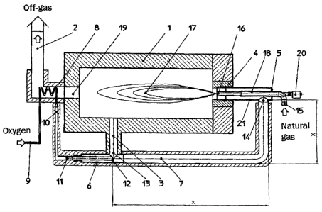
The furnace installation illustrated in Fig. 1 comprises a refractory lining 1
which
surrounds a combustion chamber and has an off-gas opening 19 and a stack 2,
which discharges the furnace off-gases, and pipeline 3 as well as a burner
block 4
with a burner 5, the burner 5 being connected by a pipeline 7 to an injector 6
and to
a heat exchanger 8 arranged in the stack 2.
The furnace off-gases which flow out of the combustion chamber through the off-
- 7 -
CA 02627016 2008-04-23
WO 2007/048428
PCT/EP2005/011562
gas opening 19 are cooled as they flow around the heat exchanger 8 and then
flow
out of the furnace installation through the stack 2.
The gaseous oxygen, which is used as oxidizing agent at a temperature of from -
20
to 40 C and at a pressure of from 0.2 to 40 bar, flows into the heat exchanger
8
through an inlet 9.
The oxygen flowing through the heat exchanger 8, which is designed as a recu-
perator or regenerator, is heated by the furnace off-gases flowing around the
heat
exchanger 8 and flows through an outlet 10 of the heat exchanger 8 into the
injec-
tor 6 through an inlet 11 at a temperature of from 20 to 900 C.
The oxygen which flows out of the outflow nozzle 12 of the injector 6 at a
velocity
of from 20 to 660 m/s expands, thereby generating an oxygen jet flowing at a
ve-
locity of from 20 to 660 m/s.
The high flow velocity of the oxygen jet generates a reduced pressure at
position
13 in the injector 6, the sucking action of which reduced pressure sucks the
furnace
off-gases out of the combustion chamber through the pipeline 3 into the oxygen
jet, and in the pipeline 7, which is designed as a mixing section of length x,
they
are mixed with the oxygen jet, with temperature balancing, after which the
mixture
of oxygen and furnace off-gases is fed, at a temperature of from 20 to 1600 C,
through a connection 14 to the burner 5, which via a further connection 15 is
sup-
plied with natural gas as gaseous fuel.
The pipelines carrying the oxygen and the furnace off-gases consist of a heat-
resistant NiCr or ODS alloy and are provided on the inner side with a thermal
pro-
tection and/or on the outer side with a thermal insulation, e.g. comprising
ceramic
fibres or ceramic blocks.
The burner 5, which is used as a parallel-flow burner, advantageously has an
inner
tube and an outer tube, with the natural gas used as gaseous fuel flowing to
the
burner mouth 16 through the fuel tube 18, which is arranged as the inner tube,
and
- 8 -
CA 02627016 2008-04-23
WO 2007/048428
PCT/EP2005/011562
the mixture of oxygen and furnace off-gas flowing to the burner mouth 16
through
the outer tube, which accommodates fuel tube 18 and is designed as an annular
gap
21, generating a long, soft and visible burner flame 17 in the combustion
chamber
of the furnace installation for heating material that is to be treated.
Partial self-carburization of the fuel takes place in the fuel tube 18 of the
burner 5
through recuperative heat exchange with the mixture of oxidizing agent and fur-
nace off-gases.
The burner structure according to the invention allows the mixture of
oxidizing
agent and furnace off-gases to flow out of the burner mouth 16 of the burner
at a
velocity which is 0.3 to 4 times higher than the fuel, with the result that a
total
momentum flux, based on the burner power, of from 1.5 to 8 N/MW and a ratio of
the momentum flux densities of the mixture of oxidizing agent and furnace off-
gases to fuel of from 0.8 to 31 are ensured, and as a result a power density
of from
0.2 to 0.5 KW/mm2 is reached at the outlet of the burner block 4.
The mixture of oxidizing agent and furnace off-gases flows out of the burner
mouth 16 at a velocity of from 20 to 80 m/s.
The burner flame which burns the material that is to be treated in the
combustion
chamber has a flame temperature of from 800 C to 2700 C.
The burner block 4 which accommodates the burner 5 has a preferably
cylindrical
opening.
The burner is advantageously equipped with a UV light receiver 20 for flame
monitoring.
The furnace installation which is diagrammatically depicted in Fig. 2 is
advanta-
geously used if the furnace off-gases are ladened with dust or other
substances
which are aggressive or promote oxidation. This furnace installation comprises
the
refractory lining 1, which surrounds a combustion chamber of a furnace
installa-
- 9 -
CA 02627016 2008-04-23
WO 2007/048428
PCT/EP2005/011562
tion and has an off-gas opening 19, and a stack 2, which discharges the
furnace
off-gas and accommodates the heat exchanger 8, as well as the burner block 4,
which contains the burner 5 and is connected by a pipeline 7 to the injector 6
and
the heat exchanger 8.
The furnace off-gases which flow out of the combustion chamber through the off-
gas opening 19 are cooled as they flow around the heat exchanger 8, which is
sup-
plied with water, and then flow out of the furnace installation via the stack
2.
As it flows through the heat exchanger 8, the water which is fed to the heat
ex-
changer 8 through the inlet 9 is evaporated through heat exchange with the
furnace
off-gas flowing around the heat exchanger 8 and then flows into the injector 6
at
position 13 as superheated steam at a temperature of from 20 to 900 C.
The gaseous oxygen, which is used as oxidizing agent at a temperature of from -
20
to 40 C and a pressure of from 0.2 to 40 bar, flows into the injector 6
through the
inlet 11. The oxygen jet expanding as it flows out of the outflow nozzle 12 of
the
injector 6 increases its flow velocity to 20 to 340 m/s, with the result that
a reduced
pressure is generated at position 13 in the injector 6, the sucking action of
which
reduced pressure sucks the superheated steam into the oxygen jet flowing
through
the injector 6 at position 13 and mixes it with the oxygen jet, with
temperature
balancing, in the pipeline 7, which is designed as mixing section of length x,
and
the oxygen/steam mixture flows, at a temperature of from 20 to 1600 C, through
connection 14 into the burner 5, which is supplied through connection 15 with
natural gas as gaseous fuel.
The pipelines carrying the oxygen and the steam consist of a heat-resistant
and
corrosion-resistant NiCr or ODS alloy and are designed from the inside with a
thermal protection or from the outside with a thermal insulation, e.g.
comprising a
ceramic fibre or ceramic block.
The burner 5, which is used as a parallel-flow burner, advantageously has an
inner
tube and an outer tube, natural gas which is used as gaseous fuel flowing to
the
-10-
CA 02627016 2008-04-23
WO 2007/048428
PCT/EP2005/011562
burner mouth 16 through the fuel tube 18, which is arranged as an inner tube,
and
the mixture of oxygen and steam flowing to the burner mouth 16 through the
outer
tube, which accommodates the fuel tube 18 and is designed as an annular gap
21,
thereby generating the long, soft and visible burner flame 17 with a flame
tempera-
tare of from 800 C to 2700 C in the combustion chamber of the furnace installa-
tion for heating material that is to be treated.
Partial self-carburization of the fuel takes place in the fuel tube 18 of the
burner 5
through recuperative heat exchange with the mixture of oxidizing agent and
steam.
The burner design according to the invention allows the mixture of oxidizing
agent
and steam to flow out of the burner mouth 16 of the burner at a velocity which
is
0.3 to 4 times higher than the fuel, with the result that a total momentum
flux,
based on the burner power, of from 1 to 8 N/MW and a ratio of the momentum
flux densities of the mixture of oxidizing agent and steam to fuel of from 0.8
to 31
are ensured, and as a result a power density of from 0.2 to 0.5 KW/mm2 is
reached
at the outlet of the burner block 4.
The mixture of oxidizing agent and steam flows out of the burner mouth 16 at a
velocity of from 20 to 80 m/s.
The burner block 4 has a preferably cylindrical opening.
The burner is equipped with a UV light receiver 20 for flame monitoring.
The furnace installation which is diagrammatically depicted in Fig. 3 is used
if the
furnace off-gases are ladened with dust or other aggressive or oxidation-
promoting
substances. This furnace installation comprises the refractory lining 1, which
sur-
rounds a combustion chamber and has an off-gas opening 19, and the stack 2,
which is designed to discharge the furnace off-gas and contains the heat
exchanger
8, as well as the burner block 4 with burner 5, burner 5 being connected to
the in-
jector 6 and to the heat exchanger 8 by a pipeline 7.
- 11 -
CA 02627016 2008-04-23
WO 2007/048428
PCT/EP2005/011562
The exhaust gases which flow out of the combustion chamber through the off-gas
opening 19 are cooled as they flow around the heat exchanger 8, which is
supplied
with carbon dioxide, and then flow out of the furnace installation through the
stack
2.
Liquid or preferably gaseous carbon dioxide which is supplied through the
inlet 9
of the heat exchanger 8 is heated to 20 C to 900 C through heat exchange with
the
furnace off-gas flowing around the heat exchanger 8 and flows through the
outlet
into the injector 6 at position 13.
The gaseous oxygen, which is used as oxidizing agent at a temperature of from -
20
to 40 C and a pressure of from 0.2 to 40 bar, is fed to the injector 6 through
the
inlet 11. The oxygen flowing through the injector 6 expands as it flows out of
the
outflow nozzle 12 of the injector, so that its flow velocity is increased to
from 20
to 340 m/s, with the result that a reduced pressure is generated in the
injector 6 at
position 13, the sucking action of which reduced pressure sucks the carbon
dioxide
into the oxygen jet, with the carbon dioxide being mixed with the oxygen jet,
with
temperature balancing, in the pipeline 7, which is designed as a mixing
section
with a length x, and then the mixture of oxygen and carbon dioxide flows, at a
temperature of from 20 to 1600 C, through connection 14 into the burner 5,
which
is supplied via a further connection 15 with natural gas as gaseous fuel.
The pipelines carrying the oxygen and the carbon dioxide consist of a heat-
resistant and corrosion-resistant NiCr or ODS alloy and are provided on the
inner
side with a thermal protection and/or on the outer side with a thermal
insulation,
e.g. comprising ceramic fibres.
The burner 5, which is used as a parallel-flow burner, advantageously has an
inner
tube and an outer tube, with natural gas used as gaseous fuel being fed to the
burner mouth 16 through the fuel tube 18, which is arranged as the inner tube,
and
the mixture of oxygen and carbon dioxide being fed to the burner mouth 16
through the outer tube, which accommodates the fuel tube 18 and is designed as
an
annular gap 21, producing a long, soft and visible burner flame 17 with a
flame
-12-
CA 02627016 2008-04-23
WO 2007/048428
PCT/EP2005/011562
temperature of from 800-2700 C in the combustion chamber of the furnace instal-
lation for heating material that is to be treated.
Partial self-carburization of the fuel takes place in the fuel tube 18 of the
burner 5
through recuperative heat exchange with the mixture of oxidizing agent and
carbon
dioxide.
The burner design according to the invention allows the mixture of oxidizing
agent
and carbon dioxide to flow out of the burner mouth 16 of the burner at a
velocity
which is 0.3 to 4 times higher than the fuel, with the result that a total
momentum
flux, based on the burner power, of from 1.5 to 8 N/MW and a ratio of the
momen-
tum flux densities of the mixture of oxidizing agent and carbon dioxide to
fuel of
from 0.8 to 31 are ensured, and as a result a power density of from 0.2 to 0.5
KW/mm2 is reached at the outlet of the burner block 4.
The mixture of oxidizing agent and carbon dioxide flows out of the burner
mouth
16 at a velocity of from 20 to 80 m/s.
=
The burner block 4 has a preferably cylindrical opening.
The burner is equipped with a UV light receiver 20 for flame monitoring.
- 13 -
CA 02627016 2008-04-23
WO 2007/048428
PCT/EP2005/011562
List of designations
1 Refractory lining
2 Stack (furnace off-gas)
3 Pipeline (furnace off-gas)
4 Burner block
Burner
6 Injector
7 Pipeline
8 Heat exchanger
9 Inlet (8)
Outlet (8)
11 hilet (6)
12 Outflow nozzle (6)
13 Position (6)
14 Connection (5)
Connection (5)
16 Burner mouth
17 Burner flame
18 Fuel tube
19 Off-gas opening
UV light receiver
21 Annular gap
- 14 -