Note: Descriptions are shown in the official language in which they were submitted.
CA 02627048 2008-04-23
GEAR MECHANISM, IN PARTICULAR LINKAGE MECHANISM
DESCRIPTION
The invention relates to a gearbox, in particular a linkage gear for a
handling
device with a base unit and with a rotating unit that is supported around a
linkage
axis relative to the base unit. Such linkage drives are used, for example, in
the
fields of automation or robotics, for example to reliably implement
positioning or
grasping movements of handling devices.
Known from DE 32 30 648 C2 is an angular reversing gear with two succeeding
planetary sets, where two crown wheels arranged along an axis are driven in
opposite directions by a drive shaft.
Known from GB 442 462 is a planetary gearbox, where two bevel gear wheels
arranged along an axis are driven in opposite directions by a drive shaft. The
bevel gear wheels exhibit pinions that mesh with spur wheels. The spur wheels
themselves are coupled in a movable fashion via bevel pinions.
Known from GB 922 005 is a reduction gear, where two crown wheels arranged
along an axis are driven in opposite directions by an input shaft. The two
crown
wheels are coupled in a moveable fashion via sun wheels located opposite each
other. It is the objective of the present invention to provide gear boxes that
have
a compact design, realize high gear ratios and exhibit a high power density.
This objective is achieved by a gearbox with the features of claim 1. With
such an
arrangement, a gear unit with a very compact design can be realized that
exhibits
a high reducing ratio and that can transmit great forces. According to the
1
CA 02627048 2008-04-23
invention, the mentioned advantages can be realized in a small design space by
splitting the rotational movement of the drive element onto the two rotating
members and through the functional connection of the two coupling elements
with each other.
.5
It is advantageous if the drive element is arranged perpendicular to the
linkage
axis such that a drive shaft of a motor that can be coupled with the drive
element
can be arranged perpendicular to the linkage axis as well and coaxial or axis-
parallel to the rotational axis of the drive element. ~.~ 10
To achieve a high reducing ratio of the gearbox, the functional connections of
the
individual gear components can be realized according to the three independent
and freely combinable approaches:
a) Providing differing reducing or gear ratios between the drive element
15 and the two rotating members,
b) Providing differing reducing or gear ratios between the rotating
members and the respective associated coupling elements, and
c) Providing a reducing or gear ratio other than 1 for the two coupling
elements with each other.
Depending on the expectation profile on the gearbox, the approaches mentioned
under a), b) and c) can be realized individually or in combination in order to
achieve a rotational movement of the rotating member around a rotational axis.
In particular, a slightly different gear ratio or reducing ratio of the
rotational
movements of the coupling elements may be provided, which in the end will lead
to the turning of the rotational unit versus a turning of the base unit.
2
CA 02627048 2008-04-23
According to a development of the invention, it is provided that the two
rotating
members are designed as gear rings, whereby the coupling elements are each
arranged in a rotational coupling fashion at the inner circumference of one
gear
ring with the respective gear ring. The coupling elements are arranged such
that
they are able to rotate around their own longitudinal axis, which runs axis-
parallel
to the linkage axis, as well as around the linkage axis. When the drive
element
turns, the coupling elements run - rotating around their own longitudinal axis
-
along the inner circumferences of the gear rings in the fashion of planets.
Through this design, the gearbox can be realized in a very compact manner =
because coupling elements running in the gear rings utilize the design space
that
is radially on the inside of the gear rings.
In particular it can be provided that the inner diameters of the two gear
rings are
at least slightly different. This can result in a turning of the rotating unit
in relation
to the base unit.
An additional advantageous design of the invention provides that the coupling
elements are designed as shaft sections that extend at least in part through
the
two gear rings and that are rotationally mounted at the cage with their free
ends.
This achieves an advantageous and space-saving support for the coupling
elements. The coupling elements can each exhibit a first coupling area in
functional connection with its assigned gear ring and a second coupling area
in
functional connection with the respective other coupling element. The two
coupling areas of the coupling elements can be identical or different. With
identically designed coupling areas, it is conceivable that the two coupling
areas
merge into each other, leading to a simplified and therefore more cost-
effective
manufacture of the coupling elements.
3
CA 02627048 2008-04-23
According to another embodiment of the invention, it can be provided that the
two
rotating members exhibit outer wheel sections that interact through their
outer
circumferences with the coupling elements. This embodiment has the advantage
over the embodiment with the gear rings that the rotating members can be
supported in the area of their rotational axis. The respective coupling
elements
run along the outer circumferences. The outer diameters of the two outer wheel
sections can be different.
According to the invention, it may also be advantageous if the cage is
rotationally
mounted to the base unit for turning the rotating unit. Since the cage is
turned,
~l)
the entire rotating unit can be turned via the cage through an appropriate
support
of the cage at the base unit.
In case relatively high forces are to be transmitted via the gearbox, the
drive
element can be located as a bevel pinion between the two rotating members,
which are then designed as bevel gear wheels that mesh with the bevel pinion.
According to the invention, other rotating couplings can be provided as well.
For
example, the drive element can be designed as a friction wheel between the two
rotating members, which are then designed as friction discs driven by the
friction
wheel. The friction wheel can then be located in a plane perpendicular or
slanted
toward the rotating axis of the rotating discs, for example.
fl
Another embodiment of the invention stands out in that the two rotating
members
are rotationally coupled with the coupling elements and/or the two coupling
elements with each other through teeth or friction surfaces. Providing a tooth
connection suggests itself in particular in instances, when relatively high
forces
are to be transmitted.
4
CA 02627048 2008-04-23
In those cases where the movement of individual rotating components are
coupled and move together via geared teeth, gears with different numbers of
teeth can be used. For example, it is conceivable that in embodiments where
the
rotating members are designed as gear rings, the inner circumference of the
one
gear wheel exhibits one more or one less tooth than the inner circumference of
the other gear ring.
To support the rotating members that are driven by the drive element, it
conceivable according to the invention that at least one support element is
provided that is coupled in its movement with the drive element and is located
at
the base unit. The support element is, in particular, rotationally mounted and
follows the rotational movement of the rotating members. The support elements
can, in particular, be designed identical to the drive element, whereby the
support
element does not need to be driven by an additional component but follows
exclusively the rotational movement of the rotating members. Advantageously,
several support elements are provided over the circumference of the rotating
members, in particular at equal distances to each other. In this manner, it is
possible to transmit in particular great forces between the base unit and the
rotating unit.
One advantageous and compact design of the gearbox arises, when the coupling
elements are arranged axis-parallel to each other and/or axis-parallel to the
linkage axis. In addition, it is advantageous, when the rotating unit and/or
the
cage exhibits a coupling section that is arranged radially and/or axially to
the
linkage axis for arranging additional components. Additional components may
be,
for example, spacer elements and/or grasping elements and/or additional
gearboxes and/or drive units.
5
CA 02627048 2008-04-23
Additional advantages and advantageous embodiments of the invention become
apparent from the following description wherein the invention is described and
explained in greater detail based on the drawing, of which:
Figure 1 is a schematic presentation of a drive element with two rotating
members rotationally coupled to the drive element as part of a linkage gear
subject to the invention;
Figure 2 shows two rotating members rotationally coupled to a coupling
element as part of a linkage gear subject to the invention;
Figure 3 is a schematic presentation according to Figure 1 with rotating
members of different diameters;
Figure 4 is a schematic presentation corresponding to Figure 2 exhibiting
rotating members with different inner diameters;
Figure 5 is an additional embodiment of rotating members with different
coupling elements according to a linkage gear subject to the invention;
Figure 6 is a perspective external view of an additional embodiment of a
linkage gear subject to the invention;
Figure 7 shows a longitudinal section through the linkage gear according
to Figure 6; and
Figure 8 shows is a cross-section through the longitudinal section
according to Figure 7.
Figures 1 to 5 schematically show different components of linkage gears
subject
to the invention.
Figure 1 shows a drive element 10 that can be driven by a motor and that has a
shaft extension 12, which is rotationally coupled with a shaft that can be
driven
by a motor, in particular an electric motor. The drive element 10 is designed
as a
bevel wheel, exhibiting beveled toothing or a friction surface for rotational
coupling with two rotating members 14, 16 that are arranged coaxially to each
6
CA 02627048 2008-04-23
- ,i
other. The rotational axis 18 of the two rotating members 14, 16 is arranged
orthogonal to the rotating axis 11 of the drive element 10. The rotating
members
14, 16 also have a bevel wheel type design with toothings or frictional
surfaces
running at an angle to the rotating axis 18.
When turning the drive element 10 in the rotating direction indicated by the
arrow
20, the two rotating members 14, 16 turn in different directions indicated by
the
arrows 22, 24.
In Figure 2, where the drive element 10 is not shown, the two rotating members
14, 16 are designed as gear rings. A coupling element 30, 32 is rotationally
mounted around its respective longitudinal axis 13, 15 in a rotationally
coupled r
manner at the inner circumference 26 of the gear ring 14 and at the inner
circumference 28 of the other gear ring 16. The two coupling elements 30, 32
may have a functional connection to the respective inner circumference via,
for
example, toothing or a friction surface.
A rotational movement of the rotating member 14 or 16, respectively, around
the
rotating axis 18 affects a rotational movement of the coupling element 30 or
32,
respectively, around its respective longitudinal axis 13 or 15, respectively.
As is furthermore apparent from Figure 2 that the two coupling elements 30, 32
have a functional connection with each other. They can be rotationally coupled
with each other via friction surfaces or toothings.
When turning the rotating member 14 in the rotational direction 22, the
coupling
element 30 rotates around its longitudinal axis 13 in the rotational direction
indicated by the arrow 34 with the rotating member 14 via the rotating
coupling of
the coupling element 30. Correspondingly, when turning the rotating member 16,
7
CA 02627048 2008-04-23
the coupling element 32 is turned around its longitudinal axis 15 in the
rotational
direction 36. According to the invention, it is provided that the design is
such that
the longitudinal axes 13, 15 of the two coupling elements 30, 32, which are
both
rotationally mounted on a cage not shown in Figures 1 to 5, change their
relative
position in relation to the rotational axis 18 when the rotating members 14,
16 are
turned.
Figure 3 shows an embodiment, where the gear ratios from the drive element 10
to the two rotating members 14, 16 differ from each other. This results in a
~.~ 10 different rotational speed of the counter-rotating rotating members 14,
16 when
the drive element 10 is tumed. In a design that otherwise corresponds to that
of
Figure 2, the coupling elements 30, 32 move in the manner of planets, which
each rotates around its own longitudinal axis 13, 15, and additionally around
the
axis 18. The already mentioned, in Figures 1 to 5 not shown, cage, which takes
up the coupling elements 30, 32, experiences a rotation around the rotational
axis 18 as weli. In this manner, the rotational axis also constitutes the
linkage
axis, where the cage is a part of the rotating unit, which is then turned
around the
linkage axis 18.
To achieve different rotational speeds of the rotating members 14 and 16 it is
not
necessary that the rotational axis of the drive element 10 has to run at an
angle
that is 900 different to the rotational axis 18 as shown in Figure 3.
According to
the invention, different rotational speeds can be achieved also with an
orthogonal
arrangement, for example by providing toothings at the drive element 10 and
the
rotating members 14, 16, whereby in this case the toothing of the rotating
member 14 is designed different from the toothing of the rotating member 16.
In Figure 4, a relative movement of the longitudinal axes 13, 15 of the two
coupling elements 30, 32 around the rotational axis 18 is achieved through a
8
CA 02627048 2008-04-23
different gear ratio of the coupling elements 30, 32 versus the respective
rotating
members 14, 16 assigned to them. When providing gear rings, as shown in
Figures 2 and 4, this can be achieved through different inner diameters 26, 28
of
the two gear rings 14, 16. In Figure 4, the inner diameter 26 of the gear ring
14 is
greater than the inner diameter 28 of the gear ring 16. If for the rotational
coupling toothings are provided at the inner diameters 26, 28 and
correspondingly counter-toothings at the coupling elements that mesh with the
toothings of the rotating members 14, 16, then the relative movement of the
two =
coupling elements 30, 32 around the rotational axis 18 can be realized through
at
least slightly different toothings. In this case, it is conceivable that the
toothings
on the side of the coupling elements are identical and that toothings with
different
numbers of teeth are provided at each of the inner diameters 26, 28.
Figure 5 shows an additional conceivable arrangement subject to the invention.
For one, the two rotating members 14, 16 in Figure 5 each provide outer wheel
sections 37, 38 that are rotationally coupled with the coupling elements 30,
32.
For another, the functional connection of the two coupling elements 30, 32 is
designed such that the related gear ratio does not equal one. For turning
rotating
members 14, 16, the result is a relative movement of the rotational axes 13,
15 of
the coupling elements 30, 32 around the axis 18.
The drive element 10 is not shown in Figures 4 and 5 for purposes of a
simplified
presentation.
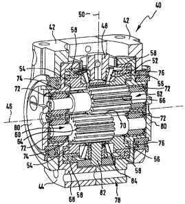
The linkage gear subject to the invention presented in Figures 6 to 8
comprises a
base unit 42 and a rotating unit 44 that is rotationally mounted around a
linkage
axis 46. The base unit 42 comprises a drive element 48 with a rotational axis
designated with the character 50 and which is rotationally mounted
perpendicular
9
CA 02627048 2008-04-23
to the linkage axis 46 and can be driven via a motor shaft. To drive the drive
element 48, a drive unit may be attached to the base unit, for example.
As is apparent, in particular in the sections of Figures 7 and 8, the drive
element
48 exhibits a bevel wheel pinion 52 that drives two rotationally mounted
rotating
members 54, 56 arranged coaxially along the linkage axis 46, in opposite
rotational directions. The two rotating members 54, 56 are designed as bevel
gear wheels with toothing pointing at each other which mesh with the toothing
of
the drive element 48. Furthermore, the rotating members 54, 56 are designed as
gear rings that are rotationally mounted at their axial outer circumference
via
respective support elements 58.
Furthermore, the linkage drive 40 provides two coupling elements 60, 62,
whereby the coupling element 60 has a functional connection with the inner
circumference of the rotating member 54 in such a manner that the coupling
element is driven around its own axis when the rotating member 54 turns. in a
[
corresponding manner, the coupling element 62 is rotationally coupled with the
inner circumference of the rotating member 56. For the rotational coupling
between the rotating members 54, 56 and the coupling elements 60, 62, the
rotating members 54, 56 exhibit at their inner circumferences toothings that
mesh
with the toothings 64, 66 that are present at the outer circumferences of the
coupling elements 60, 62. The coupling elements 60, 62 have a shaft-like
design
and are supported at their free ends at a cage 68 in a manner that allows them
to
rotate around their own longitudinal axis. In the center area of the coupling
elements 60, 62, the two coupling elements 60, 62 are rotationally coupled via
a
common toothing area 70. As is apparent, especially from Figure 7, the
toothing
area of the toothing 64 of the coupling element 60, which is in functional
contact
with the rotating member 54, transitions into the area 70 of toothing 64,
which is
in functional contact with the other coupling element 62. Correspondingly, the
CA 02627048 2008-04-23
toothing area of the toothing 66 of the coupling element 62, which is in
functional
contact with the rotating element 56, transitions into the toothing area 70,
which
meshes with the toothing 64 of the other coupling element 60.
The cage 68 with its overall U-shape exhibits at its parallel running members
74
and 76 support elements 72 for rotational support of the free ends of the
coupling
elements 60 and 62. At its area that connects the two members 74 and 76, the
cage 68 exhibits a coupling section 78 for the arrangement of additional
components. The cage 68 is covered with two housing elements 80 at its outer
lying area, when viewed in the direction of the linkage axis 46. According to
the
~.~
invention, it is also conceivable that coupling sections are also provided at
the
housing elements 80 in order to arrange additional components.
If the drive element 48 is driven by a motor, the two rotating members 54, 56
turn
at the same speed in the opposite rotational direction. In this case, the two
rotating members exhibit identical outer bevel toothing pointing toward each
other. Advantageously, the inner toothings of the two rotating members 54, 56
differ by one tooth only. This as well as the common rotational coupling of
the
coupling elements 60, 62, affect a relative movement of the longitudinal axes
of
the coupling elements 60, 62 around the linkage axis 46. Due to the support of
the coupling elements 60, 62 at the cage, the cage moves around the linkage
axis 46 when the drive element 48 turns. In the end, the rotating unit 44,
which
comprises, in particular, the cage 68, the members 74, 76 as well as the two
housing elements 80, makes a rotating movement around the axis 46 in relation
to the base component 42.
For better support of the two rotating members 54, 56 it is provided that a
total of
four support elements 82 are provided at the base unit 42. The support
elements
11
CA 02627048 2008-04-23
= ~
82 comprise rotatably supported bevel gear wheels 84 that correspond to the
bevel wheel pinion 52, where the toothings of the rotating members 54, 56 run.
Instead of providing toothing as explained based on Figures 6 to 8,
corresponding friction elements and friction surfaces, respectively, may be
provided.
Due to the design of the linkage gear 40 explained above, a linkage gear can
be
provided that can be driven via a drive element 48, which can be driven
perpendicular to the linkage axis 46, which has a very compact design,
exhibits a
very high reducing ratio and that is capable of transmitting very high forces.
12