Note: Descriptions are shown in the official language in which they were submitted.
CA 02627120 2008-03-27
SURGICAL STAPLING APPARATUS WITH POWERED RETRACTION
BACKGROUND
Technical Field
[0001] The present disclosure relates to a surgical stapling apparatus.
More
particularly, the present disclosure relates to an endoscopic surgical
stapling apparatus
including a mechanism for retracting the actuation shaft of a surgical
stapling apparatus.
Background of Related Art
[0002] Surgical devices capable of fastening tissue portions are well
known in the
art. Some of these devices include a knife to cut the tissue that has been
joined by the
fasteners. Although the fasteners are typically in the form of surgical
staples, two-part
polymeric fasteners may also be employed.
[0003] Surgical fastening instruments can include two elongated jaw
members
used to capture or clamp tissue. One jaw member typically contains a staple
cartridge
that houses a plurality of staples arranged in at least two lateral rows while
the other jaw
member has an anvil that defines a surface for forming the staple legs as the
staples are
driven from the staple cartridge. The stapling operation is usually effected
by cam
members that translate through the staple cartridge, with the cam members
acting upon
staple pushers to sequentially eject the staples from the staple cartridge. A
knife may
move axially between the staple rows to cut or open the stapled tissue between
the rows
of staples. U.S. Patent Nos. 3,079,606 and 3,490,675 disclose examples of this
kind of
instrument.
[0004] A stapling apparatus disclosed in U.S. Patent 3,499,591 also
applies a
double row of staples on each side of the incision. The patent discloses a
surgical stapler
- 1 -
CA 02627120 2014-11-13
having a disposable loading unit wherein a cam member moves through an
elongate
guide path between two sets of staggered staple carrying grooves. Staple drive
members
are located within the grooves and are positioned in such a manner so as to be
contacted
by the longitudinally moving cam member. The staple members eject the staples
in the
staple cartridge as the cam member moves axially along the elongate guide
path. Other
examples of such staplers are disclosed in U.S. Patent Nos. 4,429,695 and
5,065,929.
[0005] Each of the instruments described hereinabove is designed for use in
conventional surgical procedures wherein surgeons have direct manual access to
the
operative site. In endoscopic or laparoscopic procedures, however, surgery is
performed
through a small incision or through a narrow cannula inserted through small
entrance
wounds in the skin. Endoscopic surgical stapling devices have been developed
to address
the specific needs of endoscopic and laparoscopic surgical procedures. A few
examples
of endoscopic surgical stapling devices are disclosed in U.S. Patent No.
5,307,976; U.S.
Patent No. 5,312,023; U.S. Patent No. 5,326,013; U.S. Patent No. 5,332,142;
and U.S.
Patent No. 6,241,139.
[0006] Tyco Healthcare, LP, the assignee of the present application, has
manufactured and marketed endoscopic stapling instruments, such as the ENDO
GIATM
Universal and Universal XL instruments, for a number of years. See FIGS. 1-3.
These
instruments include a surgical stapling apparatus having a retraction
mechanism to return
surgical stapling apparatus to a retracted position. The retraction mechanism
may include
a pair of retractor knobs movably positioned along a barrel portion of a
handle assembly.
After firing staples, the retraction knobs may be manually pulled proximally
to retract the
- 2 -
CA 02627120 2008-03-27
actuation shaft of the surgical stapling apparatus to its original position.
These
instruments have provided significant clinical benefits. Nonetheless,
improvements to
these instruments are possible.
100071 For instance, it would be extremely' beneficial to provide a
surgical
stapling apparatus allowing a user to quickly and effortlessly retract the
actuation shaft of
the surgical instrument with one hand. It would also be desirable to provide a
surgical
stapling apparatus with a compact, simple, reliable and ergonomic powered
retraction
mechanism. In addition, it would be beneficial to provide a surgical stapling
apparatus
with a powered retraction mechanism that can be manually overridden.
SUMMARY
[0008] The presently disclosed surgical stapling apparatus has a handle
assembly,
an actuation shaft having a connector, and a retraction mechanism positioned
within the
handle assembly. The retraction mechanism includes a motor coupled to a
transmission
shaft, a first gear rotatably mounted on the transmission shaft, the first
gear configured to
engage a second gear, a clutch operatively attached to the second gear, a main
shaft
connected to the clutch, and a pulley coupled to the main shaft, the pulley
being
operatively attached to the connector. The surgical stapling apparatus may
further
include at least one retraction knob operatively attached to a proximal end of
the
actuation shaft and configured for manually returning the actuation shaft to
the retracted
position after firing. The actuation shaft may be attached to the at least one
retraction
knob via a coupling pin.
[0009] A cable may interconnect the proximal end of the connector and the
pulley. The cable could be maintained in tension by a spring motor coupled to
the pulley.
-3..
CA 02627120 2008-03-27
The spring motor includes a spring element wrapped around and interconnecting
at least
two arbors.
[0010] The clutch includes first and second discs. The first disc is
rotatably
connected to the second gear and the second disc is slidably and rotatably
mounted on the
main shaft. The clutch may further include a button configured to turn on the
motor and
engage the clutch.
[0011] An operator may use the retraction mechanism to return the
actuation shaft
of the surgical stapling apparatus to a retracted position by activating the
motor and
engaging the clutch.
BRIEF DESCRIPTION OF THE DRAWINGS
[0012] FIGS. 1-3 illustrate a prior art surgical stapler;
[0013] FIG. 4 is a perspective view of the handle assembly according to
an
embodiment of the presently disclosed surgical stapling apparatus;
[0014] FIG. 5 is a perspective cross-sectional view of the handle
assembly shown
in FIG. 2;
[0015] FIG. 6 is a perspective view of a portion of an embodiment of the
presently disclosed surgical stapling apparatus;
[0016] FIG. 7 is a perspective view of a portion of an embodiment of the
presently disclosed surgical stapling apparatus;
[0017] FIG. 8 is perspective view of a connector of an embodiment of the
presently disclosed surgical stapling apparatus;
[0018] FIG. 9 is a perspective view of a portion of the retraction
mechanism of an
embodiment of the presently disclosed surgical stapling apparatus;
- 4 -
CA 02627120 2008-03-27
[00191 FIG. 10 is a perspective view of a portion of the retraction
mechanism of
an embodiment of the presently disclosed surgical stapling apparatus;
[00201 FIG. 10a is a perspective view of a portion of the retraction
mechanism of
an embodiment of the presently disclosed surgical stapling apparatus;
[00211 FIG. 10b is a perspective view of a portion of the retraction
mechanism of
an embodiment of the presently disclosed surgical stapling apparatus;
[00221 FIG. 11 is a perspective view of a portion of the retraction
mechanism of
an embodiment of the presently disclosed surgical stapling apparatus; and
[00231 FIG. 12 is a perspective view of a portion of the retraction
mechanism of
an embodiment of the presently disclosed surgical stapling apparatus.
DETAILED DESCRIPTION OF THE DRAWINGS
[00241 The embodiments of the present disclosure will now be described in
detail
with reference to the drawings, in which like reference numerals designate
identical or
corresponding elements in each of the several views.
[00251 In the drawings and the description that follows, the term
"proximal," as is
traditional, will refer to the end of the stapling apparatus that is closest
to the operator,
while the term "distal" will refer to the end of the apparatus that is
farthest from the
operator.
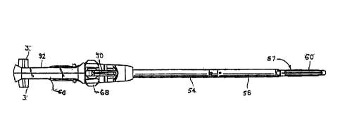
[00261 FIGS. 1-3 illustrate a prior art surgical stapling apparatus
generally
referred as 50. In the interest of brevity, this disclosure will focus
primarily on systems,
methods and structures for returning an actuation shaft of surgical stapling
apparatus 50
to its retracted position. A detailed discussion of the remaining components
and method
- 5 -
CA 02627120 2014-11-13
of use of surgical stapling apparatus 50 is disclosed in U.S. Patent No.
6,953,139.
[0027] Surgical stapling apparatus 50 is an endoscopic apparatus and
includes a
handle assembly 52 and an elongated body 54 extending therefrom. A single use
loading
unit ("SULU") 56 is releasably secured to the distal end of elongated body 54.
Although
the drawings illustrate a SULU 56, a person having ordinary skill in the art
will recognize
that other end effector may be used. SULU 56 includes a tool assembly 57
having a
cartridge assembly 58 housing a plurality of surgical staples and an anvil
assembly 60
movably secured in relation to cartridge assembly 58. As illustrated in FIGS.
1-3, SULU
56 is configured to apply at least one row of staples. SULUs may have various
staple line
lengths and configurations. Some typical SULUs have staple line lengths
measuring
from about 30 mm to 60 rum in length. SULUs for applying any number of rows of
staples, having staple pockets arranged in various patterns, or end effectors
having any
other length, are also envisioned. Loading units can include those that
provide
articulating tool assembly or a tool assembly that does not articulate, as
disclosed in U.S.
Patent No. 6,953,139.
[0028] Handle assembly 52 includes a stationary handle member 62, a movable
handle member 64, and a barrel portion 66 defining a longitudinal axis "X." A
rotatable
member 68 may be mounted on the distal end of barrel portion 66 to facilitate
rotation of
elongated body 54 with respect to handle assembly 52. An articulation lever 70
may also
be provided at the barrel portion 66 adjacent to rotatable knob 68 to
facilitate articulation
of tool assembly 57. A pair of retraction knobs 3 are movably positioned along
barrel
- 6 -
CA 02627120 2014-11-13
portion 66 to return surgical stapling apparatus 50 to a retracted position,
as will be
described in detail below.
[0029] Referring now to FIG. 4 and 5, handle assembly 52 includes a
retraction
mechanism 2 positioned generally along longitudinal axis "X" and a button 4
for
activating retraction mechanism 2. Button 4 is dimensioned and positioned so
that a user
may easily reach it. Retraction mechanism 2 further includes a retraction
drive 6
supported within handle assembly 52, and a motor 5 operatively coupled to
retraction
drive 6. An internal or external battery pack, or a cable connecting the
retraction
mechanism 2 to an external power source, may be used to energize motor 5.
[0030] Referring to FIGS. 6 and 7, rack assembly 7 has an actuation shaft 8
supported within barrel portion 66, and a release plate 9 operatively
associated with
actuation shaft 8. Actuation shaft 8 has a toothed rack 28 and its proximal
end is
connected to the pair of retraction knobs 3 via a coupling pin 10. Release
plate 9 is
configured for movement with respect to actuation shaft 8 in response to
manipulation of
retraction knobs 3 or activation of retraction mechanism 2. A pair of spaced
apart pins 29
extend outwardly from a lateral face of actuation shaft 8 to engage a pair of
corresponding angled cam slots 30 formed in released plate 9. Actuation shaft
8 is biased
proximally by spring 13. U.S. Patent No. 7,044,353, describes in detail the
structure and
manual operation of the rack assembly 7, actuation shaft 8, and release plate
9.
[0031] Referring to FIG. 5, handle assembly 52 is provided with a pawl 44
that is
mounted to selectively engage toothed rack 28 and advances the actuation shaft
8 in a
distal direction in response to manipulation of handle member 64 (see FIG. 2)
through an
- 7 -
CA 02627120 2008-03-27
actuating stroke. Pawl 44 is mounted to handle member 64 by a pivot pin 46.
The
mounting portion of pawl 44 is curved to interact with an abutment wall 45,
and the pawl
44 is rotated out of engagement with the toothed rack 28 of actuation shaft 8.
[0032] To fire apparatus 50 and apply a plurality of surgical fasteners
to a tissue
clamped in tool assembly 57, movable handle member 64 is manipulated toward a
stationary handle member 62. Thereupon, pawl 44 engages toothed rack 28 and
drives
actuation shaft 8 distally. The distal advancement of actuation shaft 8 caused
by one full
stroke of movable handle member 64 will be dictated by the size and
configuration of the
actuation shaft 8. Actuation shaft 8 may have various sizes and
configurations.
[00331 To complete the staple firing operation, movable handle member 64
is
once again approximated toward stationary handle 24, causing pawl 44 to engage
toothed
rack 28 and advance actuation shaft 8 in a distal direction another 15 mm.
Thus, in one
embodiment, two complete strokes of actuation handle 64 may cause actuation
shaft 8 to
advance 30 mm within barrel portion 66, causing the sequential ejection of all
the
surgical fasteners in staple cartridge 58. If desired, the operator can
incrementally
advance actuation shaft 8 by multiple short strokes, wherein the minimum
advancement
is dictated by the linear distance between the teeth on rack 28. Therefore,
while two
complete strokes of a stroke distance of 15 mm can be used (to fire a 30 mm
disposable
loading unit), complete strokes are not necessary or required. Surgical
stapling apparatus
50 may be configured to have various stroke distances.
[0034] With reference to FIGS. 6-8, to enable powered retraction, rack
assembly
7 may include a distally biased connector 12 having distal and proximal ends
12a, 12b. A
biasing block 13, which is positioned adjacent to proximal end 12a, biases
connecter 12
- 8 -
CA 02627120 2008-03-27
distally. Connector 12 is mounted on a top portion of rack assembly 7 and has
a hole 12c
dimensioned and configured for receiving coupling pin 10. The distal end 14a
of a cable
14 is attached to the proximal end 12b of connector 12. The proximal end 14b
of cable
14 is attached to a pulley 21 of retraction drive 6, as seen in FIG. 12.
[0035] Referring to FIGS. 9-12, retraction drive 6 includes a
transmission shaft
17 operatively connected to motor 5. A coupling 38 (FIG. 11) interconnects
motor 5 and
transmission shaft 17. A first gear 18 is rigidly mounted to transmission
shaft 17 and
configured to engage a second gear 25. First and second gears 18, 25
effectively reduce
the speed of the rotational motion supplied by motor 5. One skilled in the art
will
recognize that other speed reducing means may be utilized in lieu of first and
second
gears 18, 25. Second gear 25 is connected to hollow shaft 26. Hollow shaft 26,
in turn, is
operatively coupled to a first disc 23a of a slip clutch 23. Slip clutch 23 is
biased to its
open position and has a second disc 23b slidably and rotatably mounted on a
main shaft
20. Second disc 23b may include a tubular portion 33 having a flange 34
attached
thereto. Tubular portion 33 may surrounds at least a portion of main shaft 20.
[0036] Main shaft 20 is partially surrounded by hollow shaft 26 and is
connected
to pulley 21. Additionally, main shaft 20 interconnects pulley 21 and spring
motor 19.
Spring motor 19 may include a spring element 35 wrapped around and
interconnecting
first and second arbors 36, 37. Further, spring motor 19 may be configured to
maintain
cable 14 in tension, thereby preventing its entanglement.
[0037] With specific reference to FIG. 10, retraction drive 6 includes a
button 4
configured to turn on motor 5 and engage clutch 23. Button 4 may have a bottom
portion
4a, an elongated body portion 4b, a protrusion 4c configured to engage a
switch 24, a
- 9 -
CA 02627120 2014-11-13
hole 4e sized for receiving a tubular portion 33 of second disc 23b, and an
upper portion
4d pivotably coupled to a joint 22 of retraction drive 6. A switch 24 is
positioned
adjacent to protrusion 4c of button 4 and controls the electrical conduction
between a
motor 5 and the selected power source.
10038] With reference
to FIGS. 10a and 10b, an alternative embodiment of
retraction drive 6 includes an activation lever 74 adapted to activate on
motor 5.
Activation lever 74 has a lower portion 74a and an upper portion 74b. Lower
portion 74a
is connected to an actuation structure 75. A user can manipulate activation
lever 74
through actuation structure 75. Activation lever 74 acts along the major plane
of the
apparatus 50 to allow ergonomical activation. The upper portion 74b of
activation lever
74 is coupled to a cam 76. A lever 77 is operatively connected to cam 76 and
pivotably
coupled to an upper portion of retraction drive 6. Specifically,
lever 77 includes a
protrusion 77a configured to manipulate switch 24, an opening 77b dimensioned
to
receive tubular portion 33 (see FIG. 1I), and at least one column 77c
configured to
engage clutch 23. Switch 24 is connected to protrusion 77a of lever 77 and
controls the
electrical conduction between a motor 5 and the selected power source. Cam 76
translates the rotation of activation lever 74 with respect to a longitudinal
axis "Y" into
rotation of lever 77 with respect to longitudinal axis "X."
[0039] In operation, a
user fires a staple or any other surgical fastener using
surgical stapling apparatus 50, as discussed in detail in U.S. Patent No.
7,044,353,
by operating movable handle member 64 to advance actuation shaft 8.
Thereafter, an operator may
- 10-
CA 02627120 2008-03-27
automatically return actuation shaft 8 to its retracted position by employing
retraction
mechanism 2.
[00401 To activate retraction mechanism 2, a user must press button 4 to
turn on
motor 5 and engage clutch 23 when operating the embodiment depicted in FIG.
10.
Specifically, as a surgeon activates retraction mechanism 2, button 4 pivots
about joint 22
and slides disc 23b towards disc 23a, thus engaging clutch 23. In addition,
switch 24
allows electrical connection between a power source and motor 5, thereby
energizing
motor 5.
[0041] In the embodiment illustrated in FIGS. 10a and 10b, a user can
move
activation structure 75 to manipulate activation lever 77, thereby turning on
motor 5 and
engaging clutch 23. Specifically, as a user moves activation structure 75,
activation lever
74 rotates with respect to longitudinal axis "Y." Cam 76 transforms the
rotational motion
of lever 74 into a rotational motion of lever 77 with respect to longitudinal
axis "X."
Thereafter, lever 77 engages clutch 23 and manipulates switch 24 to activate
motor 5.
[00421 When motor 5 rotates transmission shaft 17, first gear 18 rotates
and
causes the corresponding rotation of second gear 25. The interaction of first
and second
gears 18, 25 reduces the rotation speed produced by motor 5. Clutch 23
transfers the
rotational motion of second gear 25 to main shaft 20 and, consequently, to
pulley 21. As
pulley 21 rotates, it pulls back actuation shaft 8 through cable 14. Upon
deactivation of
button 4, clutch 23 returns to its open position, and motor 5 is turned off
Alternatively,
actuation shaft 8 may be manually returned to its retracted position by
pulling retraction
knobs 3 proximally. The clutch 23, which is biased to its open position,
enables the
manual retraction of the actuation shaft 8, without engaging the motor 5. The
release
- 11 -
CA 02627120 2014-11-13
plate 9 removes the pawl from engagement with the actuation shaft 8 so that
the actuation
shaft can be retracted either manually or through the motor without
interfering with
handle 64.
[00431 The user of the surgical stapling apparatus 50 can operate the
movable
handle member 64 to fire the apparatus 50 and then use the same hand to
actuate powered
retraction of the actuation shaft 8. After retraction, the used loading unit
56 may be
replaced with another loading unit of the same or different configuration and
staples can
again be fired using the apparatus 50.
100441 In further embodiments, the firing movement and retraction of an
actuation shaft can be actuated through other mechanisms. For example, the
retraction
mechanism 2 discussed above can be used to retract an actuation shaft that has
been
driven forwards through a movable handle and gear mechanism, a motor driven
mechanism or other powered or manual actuation.
[00451 It will be understood that various modifications may be made to the
embodiments disclosed herein. Therefore, the above description should not be
construed
as limiting, but merely exemplifications of embodiments. For instance, the
described
surgical stapling apparatus 50 may be use in combination with a servomotor,
position
sensor, slide ring, electric brakes and electronic controls to add functions
such as
controlling retraction speed, sensing the limits with automatic stop, etc.
The scope of the claims should not be limited by the preferred embodiments set
forth
herein, but should be given the broadest interpretation consistent with the
description
as a whole.
- 12-