Note: Descriptions are shown in the official language in which they were submitted.
CA 02627142 2008-03-27
SELF-REGULATING ELECTRIC HEATING SYSTEM
TECHNICAL FIELD
The present invention relates to the field of
residential, commercial, and industrial heating systems.
BACKGROUND OF THE INVENTION
Electric ceiling or floor heating systems usually
comprise regular series resistive wires in which an electric
current flows. The resistance of the wires converts the
electric energy into heat. These electric heating systems are
particularly efficient as an additional heating source.
However, these systems present a fire hazard. As a result,
they cannot be installed directly in contact with wood for
example. Not leaning the heating system against the wood
implies a waste of heat and renders the heating less
efficient. Other models allow direct contact with wood, but
are limited in the thickness of the wood itself.
Therefore, there is a need for improving the safety of
heating systems of this kind without reducing their
efficiency.
SUMMARY OF THE INVENTION
In accordance with a first broad aspect, there is
provided a heating panel comprising: a heat conductive plate
having a first surface that is grooveless and planar and an
opposite surface thereof; a self-regulating heating cable
residing on the first surface; and an insulating layer
covering the self-regulating cable and the first surface to
direct the heat towards the opposite surface.
CA 02627142 2008-03-27
18910-1CA
In accordance with a second broad aspect, there is
provided a heating floor comprising: a floor having a walking
side and an underside; and at least one heating panel
attached to one of the underside and the walking side of the
floor and comprising a heat conductive plate having a first
surface that is grooveless and planar and an opposite surface
thereof; a self-regulating heating cable residing on the
first surface; and an insulating layer covering the self-
regulating cable and the first surface to direct the heat
towards the opposite surface.
In accordance with a third broad aspect, there is
provided a heating ceiling comprising: a ceiling having a top
side and an opposite bottom side; and at least one heating
panel attached to one of the top side and the bottom side of
the ceiling and comprising a heat conductive plate having a
first surface that is grooveless and planar and an opposite
surface thereof; a self-regulating heating cable residing on
the first surface; and an insulating layer covering the self-
regulating cable and the first surface to direct the heat
towards the opposite surface.
In accordance with a fourth broad aspect, there is
provided a heating wall comprising: a wall; and at least one
heating panel embedded within the wall and comprising a heat
conductive plate having a first surface that is grooveless
and planar and an opposite surface thereof; a self-regulating
heating cable residing on the first surface; and an
insulating layer covering the self-regulating cable and the
first surface to direct the heat towards the opposite
surface.
- 2 -
CA 02627142 2008-03-27
18910-1CA
BRIEF DESCRIPTION OF THE DRAWINGS
Further features and advantages of the present invention
will become apparent from the following detailed description,
taken in combination with the appended drawings, in which:
Fig. 1 is a top view of a heating panel in accordance
with one embodiment;
Fig. 2 is a cross-sectional view of a heating panel with
a flexible insulating material, in accordance with one
embodiment;
Figs. 3A and 3B are cross-sectional views of a heating
panel with a rigid insulating material, in accordance with
two embodiments for the insulating material;
Fig. 4 is a top view of a heating panel with a u-shaped
self-regulating cable having wires extending through a side
of the panel, in accordance with one embodiment;
Fig. 5 is a side view of the heating panel of figure 4;
Fig. 6 is a top view of a heating panel with a u-shaped
self-regulating cable having wires extending through a top of
the panel, in accordance with one embodiment;
Fig. 7 is a side view of the panel of figure 6;
Fig. 8 is a schematic illustrating a parallel connection
of two heating panels, in accordance with one embodiment;
Fig. 9 is a side view of a heating ceiling installed on
a top floor/roof ceiling, in accordance with one embodiment;
- 3 -
CA 02627142 2008-03-27
18910-1CA
Fig. 10 is a side view of a heating ceiling installed on
an inner ceiling, in accordance with one embodiment;
Fig. 11 is a side view of heating panels installed
underneath a floor, in accordance with one embodiment;
Fig. 12 is a side view of heating panels installed on
top of a floor with a floor cover directly on the heating
panels, in accordance with one embodiment;
Fig. 13 is a side view of heating panels installed on
top of a floor with spacing between the panels and the floor
cover, in accordance with one embodiment;
Fig. 14 is a side view of a heating panel installed on a
floor that juts out from the rest of the residence; and
Fig. 15 is a top view of heating panels embedded in side
walls, in accordance with one embodiment.
DETAILED DESCRIPTION
The heating system presented herein uses self-regulating
electric cables as a heat-source. The self-regulating cable
comprises two electric conductive wires arranged in parallel
and surrounded by a semi-conductive plastic material which
has an electric conductivity that varies with temperature. A
semi-conductive plastic material is also provided in between
the two conductive wires. The conductivity of the plastic
material is inversely proportional to temperature, and the
plastic material reduces its conductivity to a negligible
current at a predetermined threshold temperature. By applying
different electrical potentials to both conductive wires, an
electrical current flows through the semi-conductive plastic
- 4 -
CA 02627142 2008-03-27
18910-1CA
material located between both conductive wires along the
entire length of the self-adjusting cable. The flow of
current through the plastic material generates heat. The
magnitude of the current varies with the conductivity of the
plastic material, which varies with temperature. As a result,
in low temperature regions of the self-adjusting cable, both
the conductivity of and the current flowing through the
plastic material are higher, and this generates heat. In the
high temperature regions of the self-adjusting cable, both
the conductivity of and the current flowing through the
plastic material are lower, and less heat is generated. In
regions of the self-adjusting cable where the temperature is
higher than the threshold temperature, the current flow drops
to a minimum between both conductive wires and minimum heat
is generated.
In addition to regulating the temperature by itself, a
self-regulating cable also reduces the fire hazard in
comparison to traditional electric cables and wires since the
electric current drops to a minimum when the temperature of
the self-regulating cable has reached a threshold.
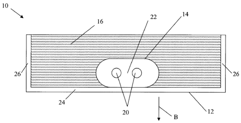
Figure 1 illustrates one embodiment of a heating panel
10. The heating panel 10 comprises a casing 12, a plurality
of self-regulating cables 14 and a thermal insulating layer
16. The casing 12 accommodates the self-regulating cables 14
and the insulating layer 16.
As shown in figure 2,. a self-regulating cable 14 is
embedded between the casing 12 and the insulating layer 16.
The self-regulating cable 14 comprises two conductive wires
20 and a plastic material 22 of which the conductivity varies
- 5 -
CA 02627142 2008-03-27
18910-1CA
with temperature. Figures 2 and 3 illustrate the cable as
having a pseudo-rectangular shape. It should be understood
that round cables may also be used, or self-regulating cables
of any other shape known to a person skilled in the art.
The casing 12 comprises a heat conductive plate 24 and
two flanges 26. The heat conductive plate 24 is made of a
heat conductive material and presents a planar surface. The
self-regulating cable 14 resides on the heat conductive plate
24 so that heat generated by the self-regulating cable 14 is
transferred to the heat conductive plate 24. As the heat
conductive plate 24 is made of a heat conductive material,
the generated heat propagates along the heat conductive plate
24. The insulating layer 16 is used to direct the heat in the
direction of arrow B.
The planar shape of the heat conductive plate 24
improves the heat transfer between the self-regulating cable
14 and the heat conductive plate 24 and reduces the amount of
heat wasted in the case of a non-planar surface. The heating
panel 10 may be provided with a cover on top of the casing 12
to enclose the self-regulating cable 14 and the insulating
material 16 inside the casing 12.
In one embodiment, the self-regulating cable 14 and the
insulating layer 16 are deposited on top of the heat
conductive plate 24 and a cover is used to maintain the
assembly in position. Alternatively, the self-regulating
cable 14 and/or the insulating layer 16 can be secured on the
heat conductive plate 24. Any mechanical connector such as an
adhesive, an adhesive tape, or a heat transfer tape can be
used.
- 6 -
CA 02627142 2008-03-27
18910-1CA
In one embodiment, both the heat conductive plate 24 and
the flanges 26 are made of a heat conductive material. It
should be understood that any material characterized as
having good heat conductivity can be used. Examples of
materials are aluminium, satinized steel, galvanized steel,
regular steel, etc. Alternatively, only the heat conductive
plate 24 of the casing 12 is made of a heat conductive
material. The heat conductive plate may be rigid or flexible.
The thermal insulating layer 16 can be made of any thermal
insulating material having any form. For example, it can be
in the form of a rigid material such as polystyrene, a foam
such as opened-cell or close-cell foams, or a flexible
material such as glass wool, rock wool, acoustic lining, etc.
Figures 3A and 3B illustrate two embodiments of a
heating panel 50 comprising a rigid insulating panel 52. In
figure 3A, the insulating panel 52 comprises grooves 54
designed to accommodate the self-regulating cable 14 which is
embedded between the insulating panel 52 and a heat
conductive plate 56. In figure 3B, the insulating layer does
not have grooves and air is between the insulating panel 52
and the conductive plate 56 where the self-regulating cable
14 is not present. Another insulating material may also be
present in this space 53.
Alternatively, a heat conductive material, such as
concrete, can be present in the space 53. This conductive
material is used to create a heat mass that will redistribute
the heat generated by the self-regulating cable 14 across the
entire panel. Such a panel can be used in a sidewalk,
driveway or other to melt away snow or ice. Using concrete as
the additional conductive material makes it solid enough to
- 7 -
CA 02627142 2008-03-27
18910-1CA
withstand the weight of vehicles that may be driven over it
when covered with concrete, asphalt, stones or other. The
concrete (or other conductive material) is poured over the
cable and hardens around it, thereby embedding the self-
regulating cable 14 within this additional conductive
material. The insulating layer 52 is then placed on top of
the additional conductive layer. When positioned in the
ground for snow melting, the conductive plate 56 faces
upwards to direct the heat towards the snow and melt it away.
When used in freezers as a frost barrier, underneath
a concrete floor, the conductive plate 56 is installed face
down on the soil with the insulating material facing up
towards the floor.
The insulating panel 52 illustrated in figures 3A and 3B
is rigid, which increases the mechanical resistance of the
heating panel 50. The conductive plate 56 can be fixed to the
insulating panel 52 by an adhesive or other types of fixing
means. In one embodiment, the self-regulating cable 14 and
the insulating panel 52 are embedded into a casing such as
casing 12 illustrated in figure 2. A cover may also be
provided to maintain the assembly into position. In this
case, the insulating panel does not need to be fixed to the
casing.
Since each one of the conductive wires 20 of the self-
adjusting cable 14 only needs to be connected to a respective
electrical potential at one end of the cable, the self-
adjusting cable 14 can be cut anywhere along its length. Any
shape can be given to the self-adjusting cable.
- 8 -
CA 02627142 2008-03-27
18910-1CA
Figure 4 illustrates one embodiment of a heating panel
60 comprising a U-shaped self-regulating cable 62 embedded in
a casing 64. It should be understood that the U-shape is one
of many configurations possible for the self-regulating cable
62 and should not be considered limiting. Other possible
configurations are a straight line, circular shapes, closed
perimeters, etc. For simplification purposes, the insulating
layer is not shown in figure 4. The self-regulating cable 62
has a U-shape that improves the heat distribution along the
heat conductive plate of the casing 64. An electrical wire
protector 66 is positioned on one side of the casing 64
around an aperture on one end thereof. The feeder wires 68
comprise a ground feeder wire and' two electrical wires
connected to different potentials. The feeder wires 68 enter
the aperture and are connected to the conductive wires 70 of
the self-regulating cable 62 and to a ground wire 72. The
ground wire 72 is connected to a ground screw 74, as
illustrated in figure 5, in order to ground the casing 64.
Figure 6 illustrates one embodiment of a heating panel
80 having a junction box 82 located on top of a casing 84.
For simplification purposes, the insulation layer is not
shown in figure 6. The feeder wires 68 enter the junction box
82 and are connected to the conductive wires 86 of a self-
regulating cable 88 and to a ground wire, as illustrated in
figure 7.
Several heating panels can be used to create a heating
floor or heating ceiling, for example. Figure 8 illustrates
one embodiment of the parallel electrical connection of two
heating panels 60 to a single feeder cable 90. The feeder
cable 90 is connected to a power supply (not shown) and
- 9 -
CA 02627142 2008-03-27
18910-1CA
comprises two conductive feeder wires 92 having a different
electrical potential and a ground feeder wire 94. The feeder
cable 90 and the feeder wires 92, 94 are provided in the
vicinity of the connectors 66 of the heating panels 60. The
conductive wires 70 of the self-adjusting cables are
connected to the conductive feeder wires 92 and the ground
wire 72 of the heating panels 60 is connected to ground
feeder wire 94. A sleeve can be used to protect the
electrical connections.
The electrical connection principle illustrated in
figure 8 can be applied to the heating panels 60 illustrated
in figures 6 and 7 and having the connectors 82 located on
top of casing 84. The feeder cable 90 is connected to a
thermostat used to control the temperature of a room heated
by the heating panels. The thermostat turns the power on or
off according to a preset temperature.
While the feeder cable 90 and the heating panels 60 and
80 are adapted to ground the heating panels 60 and 80, it
should be noted that the heating panels 60 and 80 do not have
to be grounded between the panel and junction box since they
are spot welded together.
In one embodiment, a first group of heating panels can
be connected together in series to a first thermostat and a
second group of heating panels can be connected in series to
a second thermostat. This configuration allows both groups of
heating panels to be separately controlled. Alternatively,
each heating panel can be controlled by a corresponding
thermostat or all heating panels can be controlled by a
single thermostat.
- 10 -
CA 02627142 2008-03-27
18910-1CA
The heating panels can be used as a principal heating
system or as an additional heating system. The required
number of heating panels depends on their function. Usually,
a greater number of heating panels is required to create a
principal heating system. The heating capacity of the self-
adjusting cables and their length within a heating cable also
affect the performance of the heating system.
Figure .9 illustrates one embodiment of an outside
heating ceiling 100 installed in a roof 102. The roof 102
comprises a truss 104 on which a thermal insulation layer
106, such as glass wool, is deposited. The internal face 108
of the truss 104 is covered with a vapour barrier 110.
Heating panels 112 are secured below the vapour barrier 110
between two following furrings 114. The heating panels 112
can be any one of heating panels 10, 50, 60 and 80. The
heating panels 112 are installed with their heat conductive
plate facing down so that the generated heat goes down in the
direction of arrow B.
Figure 10 illustrates one embodiment of a heating system
120 installed in an interior ceiling. The heating panels 112
are secured below a joist 122 of an internal ceiling. The
heating panels 112 are located between two following furrings
124. The heating panels 112 are installed with their heat
conductive plate facing down so that the generated heat goes
down in the direction of arrow C. An insulating layer 128
such as glass wool is also installed on top of the heating
panels 112 in order to improve the heating of the room.
In one embodiment, the width of the heating panels 112
is substantially equal to that of furrings 114, 124 in order
- 11 -
CA 02627142 2008-03-27
18910-1CA
to facilitate the installation of a board such as a gypsum
board below the furrings 114, 124 and the heating panels 112.
It also improves the contact and the heat transfer between
the gypsum board and the heating panel. While the present
application refers to gypsum boards, it should be understood
that any other boards such as chipboards can be used.
Figure 11 illustrates one embodiment of heating system
130 installed below a floor 132. Heating panels 134 are
secured below the floor 132 between two following joists 136.
The floor 132 may be covered with ceramic tiles 138, for
example. The floor can be made of any type of material,
including wood and concrete, as is found in large commercial
buildings having a garage underneath a first floor of
offices.
Alternatively, the heating panels 134 may be embedded
between the floor 132 and the ceramic tiles 138 as
illustrated in figure 12. The heating panels 134 can be any
ones of heating panels 10, 50, 60 and 80. The heating.panels
134 are installed with the insulating layer facing down in
order to direct the generated heat in the direction of arrow
D. While figures 11 and 12 refer to ceramic tiles 138 as a
floor covering, it should be noted that other floor coverings
such as a linoleum or a carpet can cover the floor 132.
Alternatively, no floor covering can be present on top of the
floor 132.
In the case of the heating system 140 illustrated in
figure 12, the heating panels 134 are preferably of the kind
of heating panels 50 illustrated in figure 3. The heating
panels 134 are installed on top of the floor 132 below the
- 12 -
CA 02627142 2008-03-27
18910-1CA
ceramic tiles 138 with their insulating layer facing down.
Having a rigid insulating layer increases the mechanical
resistance of the heating panel so that a person can walk on
the ceramic tiles without any risk of damaging the heating
panels. It should be understood that the heating panels may
be installed on top of any type of floor, such as wood or
concrete floors.
Figure 13 illustrates an embodiment similar to that
shown in figure 12, but where a material, such as wood panels
or concrete plates are provided between the heating panels
134 and the floor covering 138. A series of posts 137 are
used to raise the floor covering 138 and provide the space.
Figure 14 illustrates another type of environment in
which a heating panel can be used to heat a floor. In this
case, the panel 134 is used to heat a floor of a room 135
which extends beyond the walls of whatever space is found
below it. Directly beneath the room 135 is the outside air
137, which would result in a colder floor if the heating
panel were not used. The heating panel 134 may be placed on
top of the floor, as illustrated in figure 12, or beneath the
floor, as illustrated in figure 11.
Figure 15 illustrates one embodiment of a wall heating
system 200 which comprises heating panels 202, 204 installed
inside walls. The heating panel 202 is used to warm up towels
laying on a towel rack 106 and the heating panels 204 are
used to heat-up the walls of a shower unit 208. The heating
panels 202 and 204 are installed inside walls behind a gypsum
board 210. The heat conductive plate of the heating panels
202, 204 is facing the gypsum board 210 in order to direct
- 13 -
CA 02627142 2008-03-27
18910-1CA
the generated heat towards the towel rack 206 and the shower
unit 208, respectively.
Heating panels can be installed in other locations such
as in the frame of a window for example. A single heating
panel may be installed either in a ceiling or in a floor at a
specific location, such as where a chair happens to be, for
example.
Having the electric heating cables be self-regulating
allows an easy installation. The self-regulating cable may be
in contact with wood without risking a fire hazard.
Conventional electric cables would fail to satisfy the fire-
safety regulations if installed directly underneath the
f loor .
The heating panels can be secured to the floor, the
ceiling or the wall with screws, adhesive, and/or special
clips supplied therefor. Any mechanical connector can be
used. The heating panels can be of any shape and size. They
can be rectangular, square or circular. They can also be
designed to fit one into the other to form a continuous floor
or ceiling for example. In addition, a same self-regulating
cable may be used by a plurality of panels, or each panel may
have its own self-regulating cable.
It should be noted that the embodiments of the invention
described above are intended to be exemplary only. The scope
of the invention is therefore intended to be limited solely
by the scope of the appended claims.
- 14 -