Note: Descriptions are shown in the official language in which they were submitted.
CA 02627458 2008-04-25
WO 2007/051186 PCT/US2006/060332
1
RESOURCE ALLOCATION FOR SHARED SIGNALING
CHANNELS
Claim of Priority under 35 U.S.C. 120
[0001] The present Application claims priority to U.S. Patent Application No.
11/261,158 entitled "SHARED SIGNALING CHANNEL," filed on October 27, 2005,
which is hereby expressly incorporated by reference herein.
BACKGROUND
Field of the Disclosure
[0002] The disclosure relates to the field of wireless communications. More
particularly, the disclosure relates to resources allocation for a shared
signaling channel
in a wireless communication system.
Description of Related Art
[0003] Wireless communication systems can be configured as multiple access
communication systems. In such systems, the communication system can
concurrently
support multiple users across a predefined set of resources. Communication
devices can
establish a link in the communication system by requesting access and
receiving an
access grant.
[0004] The resources the wireless communication system grants to the
requesting
communication device depends, largely, on the type of multiple access system
implemented. For example, multiple access systems can allocate resources on
the basis
of time, frequency, code space, or some combination of factors.
[0005] The wireless communication system needs to communicate the allocated
resources and track them to ensure that two or -more communication devices are
not
allocated overlapping resources, such that thecoxnrnunicatiori links to the
communication devices are not degraded. Additionally, the wireless
communication
system needs to track the allocated resourccs in order to track the resourccs
that arc
released or otherwise available when a communication link is terminated.
CA 02627458 2008-04-25
WO 2007/051186 PCT/US2006/060332
2
[0006] The wireless communication system typically allocates resources to
communication devices and the corresponding communication links in a
centralized
manner, such as from a centralized comrnunication device. The resources
allocated, and
in some cases de-allocated, need to be communicated to the communication
devices.
Typically, the wireless communication system dedicates one or more
communication
channels for the transmission of the resource allocation and associated
overhead.
[0007] However, the amount of resources allocated to the overhead channels
typically
detracts from the resources and corresponding capacity of the wireless
communication
system. Resource allocation is an important aspect of the communication system
and
carc needs to be taken to ensure that the channels allocated to resource
allocation are
robust. However, the wireless communication system needs to balance the need
for a
robust resource allocation channel with the need to minimize the adverse
effects on the
communication channels.
[0008] It is desirable to configure resource allocation channels that provide
robust
communications, yet introduce minimal degradation of system performance.
SRIEF SUMMARY
[0009] A shared signaling channel can be used in a wireless communication
system to
provide signaling messages to access terminals within the system. The shared
signaling
channel can be assigned to a predetermined number of sub-carriers within any
frame.
The assignment of a predetermined number of sub-carriers to the shared
signaling
channel establishes a fixed bandwidth overhead for the channel. The actual sub-
carriers
assigned to the channel can be varied periodically, and can varyaccording to a
predetermined frequency hopping schedule. The amount of signal power allocated
to
the signaling channel can vary o.n a per symbol basis depending on the power
requirements of the communication link. The shared signaling channel can
direct each
message carried on the channel to one or more access terminals. Unicast or
otherwise
directed rriessages allow the channel power to be controlled per the needs of
individual
communication links.
[0010] The disclosure includes a method of generating control channel messages
in a
wireless communication system. The method comprises assigning logical control
CA 02627458 2008-04-25
WO 2007/051186 PCT/US2006/060332
3
channel resources to physical channel resources, wherein the logical control
channel
resources are distinct from logical traffic channel resources assigned for
data
transmission and the physical channel resources correspond to combinations of
sub-
carriers and OFDM symbols. The method also comprises generating and encoding
the
at least one message, and then transmitting the at least one message on at
least a portion
of the physical channel resources. The above method may also be embodied in
separate
means structures.
[0011] The disclosure also includes apparatus configured to generate signaling
channel
messages comprising a scheduler configured to assign logical signaling channel
resources to physical channel resources, wherein the logical control channel
resources
are distinct from logical traffic channel resources assigned to traffic
channels that are
assigned for data transrnission and the physical channel resources correspond
to
combinations of sub-carriers and OFDM symbols. The apparatus also includes a
signaling module configured to generate at least one signaling message and a
transmitter
configured to transmit the at least one signaling message utilizing at least
some of the
subcarriers and OFDM symbols that are assigned to the logical signaling
channel
resources.
BRIEF DESCRIPTION OF THE DRAWINGS
[0012] The features, objects, and advantages of aspects of the disclosure will
become
more apparent from the detailed description set forth below when taken in
conjunction
with the drawings, in which like elements bear like reference numerals.
[0013] Figure 1 is a simplified functional block diagram of aspects of.a
coirununication systein having a shared signaling channel.
[0014] Figure 2 is a simplified functional block diagram of aspects of a
transmitter supporting a shared signaling channel.
[0015] Figure 3 is a simplified time-frequency diagram of aspects of a shared
signaling 'channel.
[0016] Figure 4 illustrates aspects of a method of generating signaling
messages
in a cominunication system with a shared signaling channel.
CA 02627458 2008-04-25
WO 2007/051186 PCT/US2006/060332
4
[0017] Figure 5 illustrates aspects of another method of generating signaling
messages in a communication system with a shared signaling channel.
[0018] Figure 6 illustrates aspects of a simplified apparatus for generating
signaling messages in a communication system with a shared signaling channel.
DETAILED DESCRIPTION
[0019] A shared signaling channel (SSCH) in an OFDMA wireless communication
system can be used to communicate various signaling and feedback messages
implemented within the system. The wireless communication system can implement
a
SSCH as one of a plurality of forward link communication channels. The SSCH
can be
simultaneously or concurrently shared among a plurality of access terrninals
within the
communication system.
[0020] The wireless communication systcm can communicatc various signaling
messages in a forward link SSCH. For example, the wireless communication
system
can include access grant messages, forward link assignment messages, reverse
link
assignment messages, as well as any other signaling messages that may be
communicated on a forward link channel.
[0021] The SSCH can also be used to communicate feedback messages to access
terminals. The feedback messages can include acknowledgement (ACK) messages
confirming successful receipt of access terminal transmissions. The feedback
messages
can also include reverse link power control messages that are used to instruct
a
transmitting access terminal to vary the transmit power.
[0022] The actual channels utilized in an SSCH may be all or some of the ones
described above. Additionally, other channels may be included in SSCH in
addition or in lieu of, any of the above channels.
[0023] The wireless communication system can allocate a predetermined number
of
sub-carriers, OFDM symbols, or combinations thereof to the SSCH. Assigning a
predetermined nuiimber of sub-carriers, OFDM symbols, or combinatioris thereof
to the
SSCH establishes a bandwidth-overhead for the channel. The actual-sub-
carriers,
CA 02627458 2008-04-25
WO 2007/051186 PCT/US2006/060332
OFDM symbols, or combinations thereof assigned to the SSCH can be varied
periodically, and can vary according to a predetermined frequency hopping
schedule. In
certain aspects, the identity of the sub-carriers, OFDM symbols, or
combinations thereof
assigned to the SSCH can vary across each frame.
[0024] The amount of power that is allocated to the SSCH can vary depending on
the
requirements of the communication link carrying the SSCH message. For example,
the
SSCH'power can be increased when the SSCH messages are transmitted to a
distant
access terminal. Conversely, the SSCH power can be decreased when the SSCH
messages are transmitted to a nearby access terminal. If there is no SSCH
message to
be transmitted, thc SSCH nccd not be allocated any power. Bccausc the power
allocated. to the SSCH can be varied. on a per user basis when unicast
messaging is
implemented, the SSCH requires a relatively low power overhead. The power
allocated
to the SSCH increases only as needed by the particular communication link.
[0025] The amount of interference that the SSCH contributes to the data
channels for
the various access terminals can vary based on the sub-carriers assigned to
the SSCH
and the access terminals, as well as the relative power levels of the SSCH and
the data
channels. The SSCH contributes substantially no interference for many
communication
links.
[0026] Figure 1 is a simplified functional block diagram of aspects of a
wireless
communicatian system 100 implementing a SSCH on the forward link. The system
100
includes one or more fixed elements that can be in communication with one or
more
access terminals 110a-11 Ob. Although the description of the system 100 of
Figure 1
generally describes a wireless telephone system or a wireless data
communication
system, the system 100 is not limited to implementation as a wireless
telephone system
or a wirelessdata communication system nor is the system 100 limited tb havinR
the
particular elements shown in Figure 1.
[0027] An access terminal 110a typically communicates with one or more base
stations 120a or 120b, here depicted as sectored cellular towers. Other
aspects of the
system 100 may include access points in place of the base stations 120a and
120b. In
such a system'100, the BSC 130 and MSC 140 may be omitted and may be replaced
with one or more switches, hubs, or routers.
CA 02627458 2008-04-25
WO 2007/051186 PCT/US2006/060332
6
[0028] As used herein, a base station may be a fixed station used for
communicating
with the terminals and may also be referred to as, and include some or all the
functionality of, an access point, a Node B, or some other terminology. An
access
terminal may also be referred to as, and include some or all the functionality
of, a user
equipment (UE), a wireless communication device, terminal, a mobile station or
some
other terminology.
[0029] The access terminal 1 l0a will typically communicate with the base
station, for
example 120b that provides the strongest signal strength at a receiver within
the access
terminal 110a. A second access terminal 11 Ob can also be configured to
communicate
with the same base station 120b. However, the second access terminal 1 l Ob
may be
distant from the base station 120b, and may be on the edge of a coverage area
served by
the base station 120b.
[0030] The one or more base stations 120a-120b can be configured to schedule
the
channel resources used in the forward link, reverse link, or both links. Each
base
station, 120a-120b, can communicate sub-carrier assignments, acknowledgement
messages, reverse link power control messages, and other overhead messages
using the
SSCH.
100311 Each of the base stations 120a and 120b can be coupled to a Base
Station
Controller (BSC) 140 that routes the communication signals to and from the
appropriate
base stations 120a and 120b. The BSC 140 is coupled to a Mobile Switching
Center
(MSC) 150 that can be configured to operate as an interface between the access
terminals 1 l0a-110b and a Public Switched Telephone Network (PSTN)150. In
other
a.spects, the system 100 can implement a Packet Da.ta. Serv.ing Node (PDSN) in
place or
in addition to the PSTN 150. The PDSN can operate to interface a packet
switched
network, such as network 160, with the wireless portion of the system 100. In
certain
aspects, system 150 need not utilizc a PSTN 150 and the MSC 140 may be coupled
to
the network160 directly: In additional aspects, both the MSC 140 and PSTN 150
may
be omitted and BSC 130 and/orbase stations 120 may coupled directly to a
packet
based or circuit switched network 160.
[0032] The MSC 150 can also be configured to operate as an interface between
the
access terminals 110a-11 Ob and, a network 160. The network 160 can be, for
example, a
CA 02627458 2008-04-25
WO 2007/051186 PCT/US2006/060332
7
Local Area Networlc (LAN) or a Wide Area Network (WAN). In certain aspects,
the
network 160 includes the lnternet. Therefore, the MSC 150 is coupled to the
PSTN 150
and network 160. The MSC 150 can also be configured to coordinate inter-system
handoffs with other communication systems (not shown).
[0033] The wireless communication system 100 can be configured as an OFDMA
system with communications in both the forward link and reverse link utilizing
OFDM
communications. The term forward link refers to the communication link from
the base
stations 120a or 120b to the access terminals 110a-110b, and the term reverse
link refers
to the cornmunication link from the access terminals 110a-1 lOb to the base
stations
120a or 120b. Both thc basc stations 120a and 120b and thc acccss tcrminals
110a-110b
may allocate resources for channel and interference estimation.
[0034] The base stations, 120a and 120b, and the access terminal 110 can be
configured to broadcast a pilot signal for purposes of channel and
interference
estimation. The pilot signal can include broadband pilots, a collection of
narrow band
pilots that span the overall spectrum, or combinations thereof.
[0035] The wireless communication system 100 can include a set of sub-
carriers,
alternatively referred to as tones that span an operating bandwidth of the
OFDMA
system. Typically, the sub-carriers are equally spaced. The wireless
communication
system 100 may allocate one or more sub-carriers as guard bands, and the
system 100
may not utilize the sub-carriers within the guard bands for communications
with the
access terminals 11 Oa-11 Ob.
[0036] In certain aspects, the wireless communication system 100 can include
2048
sub-carriers spanning an operating frequency band of 20 MHz, which may be
divided
into independent carriers each housing a fixed portion of the 20 MHz with its
own
SSCH and other resources. A guard band having a bandwidth substantially equal
to"the
bandwidth occupied by one or more sub-carriers can be allocated on each end of
the
operating band.
{0037] The wifeless communication system 100 can be configured to Frequency
Division Duplex (FDD) the forward and reverse links. In a FDD 'aspect, the
forward
link is frequency offset from the reverse link. Therefore, forward link sub-
carriers. are.
frequency offset froni the reverse link sub-carriers. Typically, the frequency
offset is
CA 02627458 2008-04-25
WO 2007/051186 PCT/US2006/060332
S
fixed, such that the forward link channels are separated from the reverse link
sub-
carriers by a predetermined frequency off,set. The forward link and reverse
link may
communicate simultaneously, or concurrently, using FDD.
[0038] In another aspect, the wireless communication system 100 can be
configured
to Time Division Duplex (TDD) the forward and reverse links. In such an
aspect, the
forward link and reverse links can share the same sub-carriers, and the
wireless
communication system 100 can alternate between forward and reverse link
communications over predetermined time intervals. In TDD, the allocated
frequency
channels are identical between the forward and reverse links, but the times
allocated to
thc forward and revcrsc links are distinct. A channcl estimate performed on a
forward
or reverse link channel is typically accurate for the complementary reverse or
forward.
link channel because of reciprocity.
[0039] The wireless communication system 100 can also implement an interlacing
format in one or both the forward and reverse links. Interlacing is a form of
time
division multiplexing in which the communication link timing is cyclically
assigned_ to
one of a predetermined number of interlace periods. A particular communication
link to
one of the access terminals, for example 110a, can be assigned to one of the
interlace
periods, and communications over the particular assigned communication linlc
occurs
only during the assigned interlace period. For example, the wireless
communication
system 100 can implement an interlace period of six. Each interlace period,
identified
1-6, has a predetermined duration. Each interlace period occur periodically
with a
period of six. Thus, a communication link assigned to a particular interlace
period is
active once every six periods.
[0040] Interlaced communications are part'icularly useful in, wireless
communication
systems 100 implementing an automatic repeat request architecture, such as a
Hybrid
Automatic Repeat Request (HARQ) a.lgorithm. The wireless comrnunication system
100 can implement a.HARQ architecture to process data retransmission. In such
a
system, a transinitter may send an initial transmission at a first data rate
and may
automatically retransmit the data if no acknowledgement message is received.
The
transmitter can send subsequent retransmissions at lower data rates. HARQ
incremental
rcdundancy retransmission schemcs can improvc systcm pcrformancc in terms of
providing early termination gain and robustness.
CA 02627458 2008-04-25
WO 2007/051186 PCT/US2006/060332
9
[0041] The interlace format allows sufficient time for processing of the ACK
messages prior to the next occurring assigned interlace period. For example,
an access
terminal 1 l0a can receive transmitted data and transmit an acknowledgement
message,
and a base station 120b can receive and process the acknowledgement message in
time
to prevent retransmission at the next occurring interlace period.
Alternatively, if the
base station 120b fails to receive the ACK message, the base station 120b can
retransmit
the data at the next occurring interlace period assigned to the access
terminal 110a.
[0042] The base stations 120a-120b can transmit the SSCH messages in each
interlace, but may limit the messages occurring in each interlace to those
messages
intended for access terrninals 110a-110b assigned to that particular active
interlacc. The
base stations 120a-120b can limit the amount of SSCH messages that need to be
scheduled in each interlace period.
[0043] The wireless communication system 100 can implement a Frequency
Division
Multiplex (FDM) SSCH in the forward link for the communication of signaling
and
feedback messages. Each base station 120a-120b can allocate a predetermined,
or
variable, number of sub-carriers, OFDM symbols, or combinations thereof to the
SSCH.
In other aspects, only logical resources may be assigned to the SSCH and those
resources then mapped according to a mapping scheme, which may be the same or
different as the mapping scheme for traffic channels, The wireless
communication
system 100 can be configured to allocate a fixed, or variable, bandwidth
overhead to the
SSCH. Each base station 120a-120b can allocate a predetermined percentage,
with a
minimum and maximum, of its physical channel resources, e.g. sub-carriers,
OFDM
symbols, or combinations thereof, to the SSCH. Additionally, each base station
120a or
120b may allocate a different set of physical channel resources to the SSCH.
For
example, each base station 120a or 120b can be configured to allocate
approximately
10% of the physical channel resources to the SSCH.
[0044] Each base station, for example .120b; can allocate logical resources in
the form
a plurality of nodes from a charuiel tree to the SSCH. The channel tree is a
channel
model that can include a plurality of branches that eventually terminate in
leaf or base
nodes. Each node in the tree can be labeled, and each node identifies every
node and
base node bcncath it. A leaf or base node of the trcc can correspond to the
smallest
assignable logical resource, such as a single sub-carrier, OFDM symbol, or a
CA 02627458 2008-04-25
WO 2007/051186 PCT/US2006/060332
combination of a sub-carrier and OFDM symbol. Thus, the channel tree provides
a
logical map for assigning and tracking the available physical channel
resources in the
wireless communication system 100.
[0045] The base station 120b can map the nodes from the channel tree to
physical
channel resources used in the forward and reverse links. For example, the base
station
120b can allocate a predeterrnined number of resources to the SSCH by
assigning a
corresponding number of base nodes from a channel tree to the SSCH. The base
station
120b can map the logical node assignment to a physical channel resources
assignment
that ultimately is transmitted by base station 120b.
[0046] It may be advantageous to use the logical channel tree structure or
some other
logical structure to track the resources assigned to the SSCH when the
physical channel
resource assignments can change. For example, the base stations 120a-120b can
implement a frequency hopping algorithm for the SSCH as well as other
channels, such
as data channels. The base stations 120a-120b can implement a pseudorandom
frequency hopping scheme for each assigned sub-carrier. The base stations 120a-
120b
can use the frequency hopping algorithm to map the logical nodes from the
channel tree
to corresponding physical channel resource assignments.
[0047] The frequency hopping algorithm can perform frequency hopping on a
symbol
basis or a block basis. Symbol rate frequency hopping can frequency hop each
individual sub-carrier distinct from any other sub-carrier, except that no two
node are
assigned to the same physical sub-carrier. In block hopping, a contiguous
block of sub-
carriers can be configured to frequency hop in a manner that maintains the
contiguous
block structure. In terms of the channel tree, a branch node that is higher
than a leaf
node can be assigned to a hopping algorithm. The base nodes nnder the branch
node
can follow the hoping algorithm applied to.the branch node.
[0048] The base station .120a-120b can perform frequency hopping on a periodic
basis, such as each frame, a number of frames, or some other predetermined
number of
OFDM symbols. As used herein, a frame refers to a predetermined structure of
OFDM
symbols, which may include one or more preamble symbols and one or more data
symbols. The receiver can be configured to utilize the same frequency hopping
CA 02627458 2008-04-25
WO 2007/051186 PCT/US2006/060332
11
algorithm to determine which sub-carriers are assigned to the SSCH or a
corresponding
data channel.
[0049] The base stations 120a-120b can modulate each of the sub-carriers
assigned to
the SSCH with the SSCH messages. The messages can include signaling messages
and
feedback messages. The signaling messages can include access grant messages,
forward link assignment block messages, and reverse link block assignment
messages.
The feedback messages can include acknowledgement (ACK) messages and reverse
link power control messages. The actual channels utilized in an SSCH may be
all or
some of the ones described above. Additionally, other channels may be included
in
SSCH in addition or in lieu of, any of thc abovc channcls.
[0050] The access grant message is used by the base station 120b to
acknowledge an
access attempt by an access terminal 110a and assign a Media Access Control
Identification (MACID). The access grant message can also include an initial
reverse
link channel assigmnent. The sequence of modulation symbols corresponding to
the
access grant can be scrambled according to an index of the preceding access
probe
transmitted by the access terminal 110a. This scrambling enables the access
terminal
110a to respond only to access grant blocks that correspond to the probe
sequence that it
transmitted.
[0051] The base station 120b can use the forward and reverse link access block
messages to provide forward or reverse link sub-carrier assignments. The
assignment
messages can also include other parameters, such as modulation format, coding
format,
and packet format. The base station typically provides a channel assignment to
a
particular access terminal 110a, and can identify the target recipient using
an assigned
MACID.
[0052) The base stations 120a-120b typically transmit the ACK messages
to'particular
access terminals 110a-1 l Ob in response to successful receipt bf.a
transmission. Each.
ACK message can be as simple as a one-bit message indicating positive or
negative
acknowledgement. An ACK message can be linked to each sub-carrier, e.g. by
using
related nodes in a channel tree to others for that access terminal, or can be
linked to a
particular MACID. Further, the ACK messages may be encoded over multiple
packets
for the purposes of diversity.
CA 02627458 2008-04-25
WO 2007/051186 PCT/US2006/060332
12
[0053] The base stations 120a-120b can transmit reverse link power control
messages
to control the power density of reverse link transmissions from each of the
access
terminals 110a-110b. The base station 120a-120b can transmit the reverse power
control message to command the access terminal 110a-110b to increase or
decrease its
power density.
[00541 The base stations 120a-120b can be configured to unicast each of the
SSCH
messages individually to particular access terminals 110a-110b. In unicast
messaging,
each message is modulated and power controlled independently from other
messages.
Alternatively, messages directed to a particular user can be combined and
independently
modulated and powcr controlled.
[0055] In another aspect, the base stations 120a-120b can be configured to
combine
the messages for multiple access terminals 110a-110b and multi-cast the
combined
message to the multiple access terminals 110a-1 lOb. In multicast, messages
for
multiple access terrninals can be grouped in jointly encoded and power
controlled sets.
The power control for the jointly encoded. messages needs to target the access
terminal
having the worst communication link. Thus, if the messages for two access
terminals
110a and 110b are combined, the base station 120b sets the power control of
the
combined message to ensure that the access terminal 110a having the worst link
receives the transmission. However, the level of power needed to ensure the
worst
communication link is satisfied may be substantially greater than required for
an access
terminal 110b at a close proximity to the base station 120b. Therefore, in
some aspects
SSCH messages may be jointly encoded and power controlled for those access
terminals
having substantially similar channel characteristics, e.g. SNRs, power
offsets, etc.
[0055] 'Inanother aspect, the base stations 120a-120b can group all of the
message
information forall access terminals 11 0a-l lOb served by a base station, for
example
120b, and broadcast the combined message to all of the access terminals 110a-
110b. In
the broadcast approach,.e all messages are jointly coded and modulated while
power
conti-ol targets the access terminal with the worst forward link signal
streiigth.
[0057] Unicast signaling may be advantageous in those situations where
multicast and
broadcast reqizire substantial power overhead to reach cell edge for a
substantial number
of bits. Unicast messages may bcncfit from power sharing bctwccn acccss
terminals
CA 02627458 2008-04-25
WO 2007/051186 PCT/US2006/060332
13
with different forward linlc signal strength through power control. Unicast
messaging
also benefits from the fact that many reverse link base nodes may not be
assigned at any
given point in time so that no energy needs to be expended reporting an ACK
for those
nodes.
[0058] From the MAC logic standpoint, unicast design enables the wireless
communication system 100 to scramble ACK messages with the target MACID,
preventing an access terminal that erroneously thinks that it is assigned the
relevant
resources targeted by the ACK (via assignment signaling errors such as missed
de-
assignment) from falsely interpreting the ACK that is actually intended for
another
MACID. Thus, such an acccss tcrrninal will rccovcr from the erroneous
assignment
state after a single packet since that packet cannot be positively
acknowledged, and the
access terminal will expire the erroneous assignment.
[0059] From the link performance standpoint, the main advantage of broadcast
or
multicast methods is. coding gain due to joint encoding. However, the gain of
power
control exceeds substantially coding gain for practical geometry
distributions. Also,
unicast messaging can exhibit higher error rates compared to jointly encoded
and CRC
protected messages. However, practically achievable error rates of 0.01 % to
0.1 % are
satisfactory.
[0060] It may be advantageous for the base stations 120a-120b to multicast or
broadcast some messages while unicasting others. For example, an assignment
message
can be configured to automatically de-assign resources from the access
terminal that is
currently using resources corresponding to the sub-carriers indicated in the
assignment
message. Hence, assignment messages are often multicast since they target both
the,
intended recipient of the assignment as well as any current users of the
resources
specified in the assignment rnessage.
[0061] . Figure 2 is a simplified functional block diagram of an aspect of an
OFDMA
transmitter 200 such as can be incorporated within a base station of the
wireless
communication systemof Figure 1. The transmitter 200 is configured to transmit
one or-
more OFDMA signals. to one or more access terminals. The transmitter 200
includes a
SSCH module 230 configured to generate and implement a SSCH in the forward
link.
CA 02627458 2008-04-25
WO 2007/051186 PCT/US2006/060332
14
[0062] The transmitter 200 includes a data buffer 210 configured to store data
destined for one or more access terminals. The data buffer 210 can be
configured, for
example, to hold the data destined for each of the access terminals in a
coverage area
supported by the corresponding base station.
[0063] The data can be, for example, raw unencoded data or encoded data.
Typically,
the data stored in the data buffer 210 is unencoded, and is coupled to an
encoder 212
where it is encoded according to a desired encoding rate. The encoder 212 can
include
encoding for error detection and Forward Error Correction (FEC). The data in
the data
buffer 210 can be encoded according to one or more encoding algorithms. Each
of the
encoding algorithms and resultant coding rates can be associated with a
particular data
format of a multiple format Hybrid Automatic Repeat Request (HARQ) system. The
encoding can include, but is not limited to, convolutional coding, block
coding,
interleaving, direct sequence spreading, cyclic redundancy coding, and the
like, or some
other coding.
[0064] The encoded data to be transmitted is coupled to a serial to parallel
converter
and signal mapper 214 that is configured to convert a serial data stream from
the
encoder 212 to a plurality of data streams in parallel. The signal mapper 214
can
deterrnine the number of sub-carriers and the identity of the sub-carriers for
each access
terminal based on input provided by a scheduler (not shown). The number of
carriers
allocated to any particular access terminal may be a subset of all available
carriers.
Therefore, the signal mapper 214 maps data destined for a particular access
terminal to
those parallel data streams corresponding to the data carriers allocated to
that access
terminal.
[0065] A SSCH rnodule 230 is configured to generate the SSCH messages, encode
the
messages, and provide the encoded messages to the signal mapper 214. The SSCH
module 230 can also provide the identity of the sub-carriers assigned to the
SSCH. The
SSCH rnodule 230 can include a scheduler 252 configured to determine and
assign
nodes from a channel tree to the SSCH. The output of the scheduler 252 can be
coupled
to a frequency hopping module 254. The frequency hopping module 254 can be
configured to map the assigned channel tree nodes determined by the scheduler
252 to
the physical sub-carrier assignmcnts. Thc frcqucncy hopping module 254 .can
implement a predetermined. frequency hopping algorithm.
CA 02627458 2008-04-25
WO 2007/051186 PCT/US2006/060332
[0066] The signal mapper 214 receives the SSCH message symbols and sub-carrier
assignments, and maps the SSCH symbols to the appropriate sub-carriers. In
certain
aspects, the SSCH module 230 can be configured to generate a serial message
stream
and the signal mapper 214 can be configured to map the serial message to the
assigned
sub-carriers.
[0067] In certain aspects, the signal mapper 214 can be configured to
interleave each
modulation symbol from the SSCH message across all of the assigned sub-
carriers.
Interleaving the modulation symbols for the SSCH provides the SSCH signal with
the
maximum frequency and interference diversity.
[0068] The output of the signal mapper 214 is coupled to a pilot module 220
that is
configured to allocate a predetermined portion of the sub-carriers to a pilot
signal. In
certain aspects, the pilot signal can include a plurality of equally spaced
sub-carriers
spanning substantially the entire operating band. The pilot module 220 can be
configured to modulate each of the carriers of the OFDMA system with a
corresponding
data or pilot signal.
[0069] In certain aspects, the SSCH symbols are used to BPSK modulate the
assigned
sub-carriers. In another aspect, the SSCH symbols are used to QPSK modulate
the
assigned sub-carriers. While practically any modulation type can be
accommodated, it
may be advantageous to use a modulation format that has a constellation that
can be
represented by a rotating phasor, because the magnitude does not vary as a f-
unction of
the symbol. This may be beneficial because SSCH may then have different
offsets but
the same pilot references, and thereby be easier to demodulate.
[0070] The output of thepilot module 220 is coupled to an lnverse Fast Fourier
Transform (IFFT) module 222. The IFFT module 222 is configured to transform
the
OFDMA carriers to corresponding time domain symbols: Of course, a"Fast Fourier
Transform (FFT) implementation is not a requirem.ent,. and a Discrete Fourier
T'ransform (DFT) or soine other type of transform can be used to generate the
time
domain symbols: The output of the IFFT module 222 is coupled to a parallel to
serial
converter 224 that is configured to convert the parallel time domain symbols
to a serial
strearn.'
CA 02627458 2008-04-25
WO 2007/051186 PCT/US2006/060332
16
[0071] The serial OFDMA symbol stream is coupled from the parallel to serial
converter 224 to a transceiver 240. In the aspect shown in Figure 2, the
transceiver 240
is a base station transceiver configured to transmit the forward link signals
and receive
reverse link signals.
[0072] The transceiver 240 includes a forward link transmitter module 244 that
is
configured to convert the serial symbol stream to an analog signal at an
appropriate
frequency for broadcast to access terminals via an antenna 246. The
transceiver 240 can
also include a reverse link receiver module 242 that is coupled to the antenna
246 and is
configured to receive the signals transmitted by one or more remote access
terminals.
[0073] The SSCH module 230 is configured to generate the SSCH messages. As
described earlier, The SSCH messages can include signaling messages.
Additionally,
the SSCH messages can include feedback messages, such as ACK messages or power
control messages. The SSCH module 230 is coupled to the output of the receiver
module 242 and analyzes the received signals, in part, to generate the
signaling and
feedback messages.
[0074] The SSCH module 230 includes a signaling module 232, an ACK module 236,
and a power control module 238. The signaling module 232 can be configured to
generate the desired signaling messages and encode them according to the
desired
encoding. For example, the signaling module 232 can analyze the received
signal for an
access request and can generate an access grant message directed to the
originating
access terminal. The signaling module 232 can also generate and encode any
forward
link or reverse link block assignment messages.
[0075] Similarly, the ACK module 236 can generate ACK messages directed to
access terminals for which a transmissiori was successfully received. The ACK
module
236 can be configured to generate unicast, multicast, or broadcast messages,
depending
on the system configuration.
[0076] The power control module 238 can be configured to generate any reverse
link
power control messages based in part on the received signals. The power
control
module 238 can also be configured to generate the desired power control
messages.
[0077] The power control module 238 can also be configured to generate the
power
control signals that control the power density of the SSCH messages. The SSCH
CA 02627458 2008-04-25
WO 2007/051186 PCT/US2006/060332
17
module 230 can power control individual unicast messages based on the needs of
the
destination access tenninal. Additionally, the SSCH module 230 can be
configured to
power control the multicast or broadcast messages based on the weakest forward
link
signal strength reported by the access terminals. The power control module 238
can be
configured to scale the encoded symbols from each of the modules within the
SSCH
module 230. In another aspect, the power control module 238 can be configured
to
provide control signals to the pilot module 220 to scale the desired SSCH
symbols_ The
power control module 238 thus allows the SSCH module 230 to power control each
of
the SSCH messages according to its needs. This results in reduced power
overhead for
thc SSCH.
[0078] It should be noted that one or more elements d.epicted. in Fig. 2, may
be
integrated into a processor with integrated or and external memory module.
[0079] Figure 3 is a simplified time-frequency diagram 300 of an aspect of a
shared
signaling channel, such a channel generated by the SSCH module of the
transmitter of
Figure 2. The time frequency diagram 300 details the SSCH sub-carrier
allocation for
two successive frames, 310 and 320. The two successive frames 310 and 320 can
represent the successive frames of an FDM system of a TDM system, although the
successive frames in a TDM system may have one or more intervening frames
allocated
to reverse link access terminal transmissions (not shown).
[0080] The first frame 310 includes three frequency bands, 3 12a-3 12c, that
can be
representative of three separate sub-carriers assigned to the SSCH in the
particular
frame. The three sub-carrier assignments 312a-312c are shown as maintained
over the
entire duration of the frame 310. In some aspects, the sub-carrier assignments
can
change during the course of the frame 310. The number of times that the sub-
carrier
assignments can,change during the course of a frame 31.0 is defined by the
frequency
hopping algorithm, and is typically less than the number of OFDM symbols in
the frame
310.-
[0081] In the aspect shown in Figure 3, the sub-carrier assignment~ changes on
the
frame boundary. The second, successive frame 320 also includes the same number
of
sub-carriers assigned to the SSCH as in the first frame 310. In certain
aspects, the
numbcr of sub-carricrs assigncd to thc. SSCH is prcdctcrmizicd and fixcd. For
cxamplc,
CA 02627458 2008-04-25
WO 2007/051186 PCT/US2006/060332
18
the SSCH bandwidth overhead can be fixed to some predetermined level. In
another
aspect, the number of sub-carriers assigned to the SSCH is variable, and can
be assigned
by a system control message. Typically, the number of sub-carriers assigned to
the
SSCH does not vary at a high rate.
[0082] The sub-carriers mapped to the SSCH can be determined by a frequency
hopping algorithm that maps a logical node assignment to a physical sub-
carrier
assignment. In the aspect shown in Figure 3, the three sub-carrier physical
assigmnents
322a-322c are different in the second, successive frame 320. As before, the
aspect
depicts the sub-carrier assignments as stable for the entire length of the
frame 320.
[0083] It should be noted that while Fig. 3 depicts an SSCH assigned to a
number of
contiguous OFDM symbols for one or more subcarriers This need not be the case
and
the SSCH may be mapped in any fashion, e.g. in a symbol rate hopping fashion
or
blocks of adjacent subcarriers, OFDM symbols, or combinations thereof for one
or more
symbols. It should be noted that as depicted in Fig. 3, the schemes for
allocating
resources may be different for dataand. SSCH channels. Further, in the case
that data
transmissions are assigned to logical control channel resources, those
assignments
would be dropped, or otherwise not carried out at the base station.
[0084] Figure 4 illustrates aspects of a method 400 of generating signaling
messages
in a communication system with a shared signaling channel. The transmitter
having the
SSCH module as shown in Figure 2 can be configured to perform the method 400.
The
method 400 depicts the generation of one frame of SSCH messages. The method
400
can be repeated for additional frames.
[0085] The method 400 begins at block 410 where the SSCH module generates the
signaling messages. The SSCH module can generate signaling messages in
response to
requests: For example, the SSCH rnodule can generate access grant messages
iri.
response to access requests. Similarly, the SSCH module can generate forward
linlc or
reverse link assignment block messages in response to a link request or a
request to
transmit data.
[0086] The SSCH module proceeds to block 412 and encodes the signaliiig
messages.
The SSCH can be configured to generate unicast messages for particular message
types,
for example access grants. The SSCH module_can be coinfigured to identify a
MA.C1D
CA 02627458 2008-04-25
WO 2007/051186 PCT/US2006/060332
19
of a destination access terminal when formatting a unicast message. The SSCH
module
can encode the message and can generate a CRC code and append the CRC to the
message. Additionally, the SSCH can be configured to combine the messages for
several access terminals into a single multicast or broadcast message and
encode the
combined messages. The SSCH can, for example, include a MACID designated for
broadcast messages. The SSCH can generate a CRC for the combined message and
append the CRC to the encoded messages.
[0087] The SSCH module can, though need not, proceed to block 414 to power
control the signaling messages. In certain aspects, the SSCH can adjust or
otherwise
scale the amplitudc of the encoded mcssagcs. In anothcr aspcct, the SSCH
module can
direct a modulator to scale the amplitude of the symbols.
[0088] The SSCH module then may, though need not, perform similar operations
for
the generation of ACK and reverse link power control feedback messages. At
block
420, the SSCH module generates the desired ACK messages based on received
access
terminal transmissions. The SSCH module proceeds to block 420 and encodes the
ACK
messages, for example, as unicast messages. The SSCH module proceeds to block
424
and adjusts the power of the ACK symbols.
[0089] The SSCH module proceeds to block 430 and generates reverse link power
control messages based, for example, on the received signal strength of each
individual
access terminal transmission. The SSCH module proceeds to block 432 and
encodes the
power control messages, typically as unicast messages. The SSCH module
proceeds to
block 434 and adjusts the power of the reverse link power control message
symbols.
[0090] The SSCH proceeds to block 440 and determines which logical resources,
such as a channel tree, are assigned to the SSCH. The SSCH module proceeds to
block
450 azid maps the physical channel resources assignment to the-,assigned
nodes. The
SSCH module can use a frequency hopping algorithm to map the logical node
assignment to the physical channel resource assignment. The frequency hopping
algorithm can be such that the same node assigninent can produce different
physical
channel resources assignments for different frames. The frequency hopper can
thus
provide a level of frequency diversity, as well as some level of interference
diversity.
CA 02627458 2008-04-25
WO 2007/051186 PCT/US2006/060332
[0091] The SSCH proceeds to block 460 and maps the message symbols to the
assigned physical channel resources. The SSCH module can be configured to
interleave
the message symbols among the assigned physical channel resources to introduce
diversity to the signal.
[0092] The symbols modulate the OFDM sub-carriers, and the modulated sub-
carriers
are transformed to OFDM symbols that are transmitted to the various access
terminals.
The SSCH module allows a fixed bandwidth FDM channel to be used for signaling
and
feedback messages while allowing flexibility in the amount of power overhead
that is
dedicated to the channel.
[0093] It should be noted that while Figure 4 illustrates generating SSCH
transmissions including signaling, acknowledgement, power control, and
assignment
messages one or more of these, along with one or more other message types may
be
utilized in place of the arrangement described.
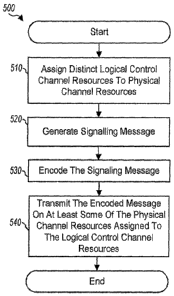
[0094] Figurc 5 illustratcs aspects of another method 500 of gencrating
signaling
messages in a communication system with a shared, signaling channel. The
method 500
may begins at block 510 where logical control channel resources are assigned
to
physical channel resources. The logical control channel resources are distinct
from
logical traffic channel resources assigned to physical channel resources for
data
transmission. In certain aspects, the distinction may be provided assigning
logical
resources only to signaling channel. In other aspects, these resources may be
reserved
for the signaling channel, but allow the system, e.g. the scheduler, to assign
any unused
logical resources reserved to the signaling channel to data transmissions.
Further, the
logical resources may be nodes of a channel tree, hop ports of a frequency hop
algorithm, or other logical resources. In certain aspects, the physical
channel resources
correspond to sub-carriers, OFDM symbols, or combinations of sub-carriers and
OFDM
symbols.,
[0095] The assignment of the resources may vary according to one or more
frequency
liopping algoritluns utilized. These hopping algorithms may vary for the
logical
resources assigned to signaling and data channels, e.g. different channel
trees may be
utilized for the logical signaling channel Tesources and the logical data
channel
resources. Further, each of the different types of signaling channel
resourccs, e.g.
CA 02627458 2008-04-25
WO 2007/051186 PCT/US2006/060332
21
signaling, acknowledgement, power control, and assignment, may have distinct
logical
resources, or may all be arbitrarily or deterministically mapped to the
logical, or
physical after assignment, resources assigned to the signaling resources.
[0096] Signaling messages may then be generated, block 520, and encoded, block
530. The messages are then transmitted based upon a mapping of symbols
corresponding to the messages to the physical channel resources assigned to
the logical
signaling channel resources, block 540. Th signaling messages may be of
signaling,
acknowledgement, power control, assignment, or other types. Further, a single
message
may have multiple signaling message types, e.g. a unicast message may have
signaling,
acknowledgcmcnts, and powcr control information for a particular user.
[0097] Additional, power control of the signaling messages or symbols thereof
may
be performed by SSCH module by adjusting or otherwise scale the amplitude of
the
encoded messages or symbols.
[00981 Although Figurc 5 depicts assignmcnt occurring prior to symbol
modulation
and encoding, the orders of the three furictions may be independent, e.g.
reversed or
contemporaneous, with respect to the three other functions.
[0099] It should be noted that in some cases, e.g. where a same channel tree
is used
for both signaling, e.g. SSCH, logical resources, and data logical resources,
a scheduler
may assign a logical resource reserved for signaling for data channels. In
such cases,
the logical resource will be dropped from the transmission resources assigned
to the
terminal. Alternatively, a re-assignment may also be possible, e.g. each
assignment of a
logical resource reserved for signaling has one or more related logical
resources to
which data assignments are transferred, when a data channel is assigned to the
logical
resource reserved for signaling.
[0100] Figure 6 illustrates aspects of a simplified "apparatus 600 for
generating
signaling messages in a communication system with a shared signaling channel.
The
apparatus includes means 610 for assigning logical control channel resources a
to
physical channel resources. The logical control channel resources are distinct
from
logical traffic channel resources assigned to physical channel resources for
data
transmission. In certain aspects, the distinction may be provided assigning
logical
res6urces only to sigrialing channel. In other aspects, these resources maybe
reserved
CA 02627458 2008-04-25
WO 2007/051186 PCT/US2006/060332
22
for the signaling channel, but allow the system, e.g. the scheduler, to assign
any unused
logical resources reserved to the signaling channel to data transmissions.
Further, the
logical resources may be nodes of a channel tree, hop ports of a frequency hop
algorithm, or other logical resources. In certain aspects, the physical
channel resources
correspond to sub-carriers, OFDM symbols, or combinations of sub-carriers and
OFDM
symbols.
[0101] The assignment of the resources may vary according to one or more
frequency
hopping algorithms utilized. These hopping algorithms may vary for the logical
resources assigned to signaling and data channels, e.g. different channel
trees may be
utilized for the logical signaling channel resources and the logical data
channel
resources. Further, each of the different types of signaling channel
resources, e.g.
signaling, acknowledgement, power control, and assignrnent, may have distinct
logical
resources, or may all be arbitrarily or deterministically mapped to the
logical, or
physical after assignment, resources assigned to the signaling resources.
[0102] Apparatus 600 includes means 620 for generating signaling messages and
means 630 for encoding the signaling messages. The messages are then
transmitted
based upon a mapping of symbols corresponding to the messages to the physical
channel resources assigned to the logical signaling channel resources by
transmitter 640.
Th signaling messages may be of signaling, acknowledgement, power control,
assignment, or other types. Further, a single message may have multiple
signaling
message types, e.g. a unicast message may have signaling, acknowledgements,
and
power control information for a particular user.
[0103] Additional, power control of the signaling messages or symbols thereof
may
be performed by means such as power control module 238..
[0104] The various illustrative logical blocks, modules, and circuits
described in
connection with the aspects disclosed herein may be implemented or performed
with a
general purpose processor, a digital signal processor (DSP), a Reduced
Instruction Set
Computer (RISC) processor, an application specific integrated circuit (ASIC),
a field
programmable gate'array (FPGA).or other programmable logic device, discrete
gate or
. .... ... .. .. , .
transistor logic, discrete hardware components, or any combination thereof
designed to
perform the functions dcscribed hcrcin. A.gencral purpose processor may be a
CA 02627458 2008-04-25
WO 2007/051186 PCT/US2006/060332
23
microprocessor, but in the alternative, the processor may be any processor,
controller,
microcontroller, or state machine. A processor may also be implemented as a
combination of computing devices, for exainple, a combination of a DSP and a
microprocessor, a plurality of microprocessors, one or more microprocessors in
conjunction with a DSP core, or any other such configuration.
[0105] The steps of a method, process, or algorithm described in connection
with the
aspects disclosed herein may be embodied directly in hardware, in a software
module
executed by a processor, or in a combination of the two.
[0106] A software module may reside in RAM memory, flash memory, non-volatile
memory, ROM memory, EPROM memory, EEPROM memory, registers, hard disk, a
removable disk, a CD-ROM, or any other form of storage medium known in the
art. An
exemplary storage medium is coupled to the processor such the processor can
read
information from, and write information to, the storage medium. In the
alternative, the
storage medium may be integral to the processor. Further, the various methods
may be
performed in the order shown in the aspects or may be performed using a
modified
order of steps. Additionally, one or more process or method steps may be
omitted or
one or more process or method steps may be added to the methods and processes.
An
additional step, block, or action may be added in the beginning, end, or
intervening
existing elements of the methods and processes.
[0107] The above description of the disclosed aspects is provided to enable
any
person of ordinary skill in the art to make or use the disclosure. Various
modifications
to these aspects will be readily apparent to those of ordinary skill in the
art, and the
generic principles defined herein may be applied to other aspects without
departing
from the spirit or scope of the disclosure. Thus, the disclosure is not
intended to be
limited to the aspects shown herein but is to be accorded the widest scope
consistent
with the principles and novel features disclosed herein.
WHAT 1S CLA11V1ED 1S: