Note: Descriptions are shown in the official language in which they were submitted.
CA 02627582 2007-11-27
WO 2006/128235 PCT/AU2006/000736
1
SPEARHEAD ASSEMBLY
Field of the Invention
The present invention relates to a spearhead assembly of
the type used in mining and subsurface drilling to enable
the coupling of down hole equipment to a wire line to
facilitate the tripping of the equipment down a drill
hole, drill string or casing.
Background of the Invention
The present Applicant is the applicant in relation to
International publication WO 2004/018831 in relation to a
spearhead assembly. The spearhead assembly in the
aforementioned International publication comprises a base
provided with a slot at one end that opens onto an outer
surface of the base. The outer surface is composed of
three contiguous surface portions. A proximal end of the
spear point is located in the slot and pivotally coupled
to the base. An opposite distal end of the spear point
extends or projects beyond the slot. The spearhead
assembly further comprises a spear point positioning
system that urges the spear point toward one of a
plurality of angularly spaced positions. These positions
are characterized by the spear point extending
substantially perpendicular to adjacent edges of the slot.
This spear point positioning system holds the spear point
in one of the positions until application of a positive
external force.
In the claims of this application and in the, description
of the,invention, except where the context requires
otherwise due to express language or necessary
implication, the words "comprise" or variations such as
"comprises" or "comprising" are used in an inclusive
sense, i.e. to specify the presence of the stated features
CA 02627582 2007-11-27
WO 2006/128235 PCT/AU2006/000736
2
but not to preclude the presence or addition of further
features in various embodiments of the invention.
It is to be understood that, if any prior art publication
is referred to herein, such reference does not constitute
an admission that the publication forms a part of the
common general knowledge in the art, in Australia or any
other country.
Summary of the Invention
According to one aspect of the present invention there is
provided a spearhead assembly comprising:
a base having an outer surface;
a slot formed in the base and having an opening that
opens onto the outer surface;
a spear point having a proximal end located in the
slot and pivotally coupled about a pivot axis to the base
to enable pivotal motion of the spear point between two
angularly spaced positions; and,
a guard coupled to the proximal end of the spear
point, the guard configured to at least partially occupy
the opening when the spear point is in at least one
location at or between the two positions, or a range of
locations at or between the two positions.
The guard has a side portion of which lies across the
opening when the guard is in the at least one or range of
locations.
The portion of the side may lie substantially flush with
the opening. However in an alternate embodiment the
portion of the side may lie proud of the opening, for
example to form a substantially continuous curve with the
outer surface. Indeed the-side may comprise different
portions which lie substantially flush with the opening
and proud of the opening respectively when the guard is in
CA 02627582 2007-11-27
WO 2006/128235 PCT/AU2006/000736
3
different locations between the two positions. That is
the side of the guard may take different shapes and
configurations. In its simplest form when the guard is in
the general configuration of a disc the side would
comprise a simple curved surface having a linear
transverse section. However in an alternative embodiment
the side or portion of the side may be of a complex
configuration and have for example a stepped, wave or
zigzag transverse section. One example of this is where
the side comprises a plurality of radially and/or axially
extending and spaced apart ribs or webs. In this
embodiment the spacing between the ribs or webs forms one
or more channels or grooves in the radially outermost
surface.
It is further envisaged that the guard may comprise a
central recess for seating the proximal end of the spear
point. The spearhead assembly may further comprise an
attachment mechanism for attaching the guard to the spear
point. In one possible embodiment, the attachment
mechanism comprises a snap coupling between the guard and
the proximal end of the spear point. This can be
facilitated by the provision of a hole or cavity in the
guard and a knob or barb-like projection at the proximal
end of the spear point that is pushed into or through the
hole or cavity.
In one embodiment the base comprises two spaced apart
walls between which the slot is defined and the opening is
formed; and, two barriers, one of each extending into the
opening on opposite sides of the slot between the spaced
apart walls. In one embodiment, the barriers may be in
the form of lips. Advantageously, one or more passages
are formed in the barrier and/or between the barrier and
the walls.
CA 02627582 2007-11-27
WO 2006/128235 PCT/AU2006/000736
4
The spearhead assembly may further comprise a fluid
channel extending through the base and in communication
with the slot to allow a fluid flow through the spearhead
assembly.
The spearhead assembly may further comprise a spear point
positioning system that urges the spear point toward, or
holds the spear point in, one of a plurality of angularly
spaced positions. The spear point positioning system may
comprise a plate through which the spear point extends,
the plate being retained on the spear point at a location
where the plate contacts the outer surface of the base.
In one embodiment, the spear point positioning system
further comprise a biasing mechanism that urges the spear
point into one of the plurality of set positions and holds
the spear point in one of the plurality of set positions.
Moreover, the biasing mechanism acts to bias the plate
against the outer surface of the base.
In one embodiment of the invention, the opening of the
slot comprises a plurality of contiguous lengths where
mutually adjacent lengths lie in respective non-parallel
planes, and wherein the plurality of set positions are
positions where the spear point extends perpendicular to
the plane of the length of the opening from which the
spear point extends.
In an alternate embodiment, the guard itself may be
configured to act as a type of spear point positioning
system. In this embodiment, the side of the guard
comprises at least two oppositely disposed straight length
the straight lengths being arranged to extend parallel to
the spear point and wherein a transverse distance between
the straight lengths is slightly smaller than an inner
diameter of the drill pipe or other conduit through which
the spear point assembly travels. It will be appreciated
CA 02627582 2007-11-27
WO 2006/128235 PCT/AU2006/000736
that by dimensioning the straight lengths in this way,
when the spear point assembly is initially entering a
drill pipe or other conduit, and the spear point is
pivoted more than say a few degrees away from the
5 longitudinal axis of the assembly, contact of one of the
straight edges with the opening of the drill pipe or
conduit will cause pivoting of the guard and spear point
so as to lie substantially parallel to the longitudinal
axis. Further, once inside the drill pipe, pivoting of
the guard or spear point marginalZy away from the
longitudinal axis will result in contact of one of the
straight edges with the inner diameter of the pipe or
conduit thereby limiting any further pivotal movement away
from the longitudinal axis. This will accordingly
maintain the spear point within a narrow arc from the
longitudinal axis thereby substantially ensuring coupling
with an overshot.
Brief Description of the Drawings
Embodiments of the present invention will now be described
by way of example only with reference to the accompanying
drawings in which:
Figure 1 is a representation of an embodiment of the
spearhead assembly in accordance with the present
invention;
Figure 2 is an enlarged view of the portion of the
spearhead assembly with the spear point inclined from a
longitudinal axis of the spearhead assembly;
Figure 3 is an enlarged view of the spearhead assembly
with the spear point extending perpendicular to the
longitudinal axis of the spearhead assembly;
CA 02627582 2007-11-27
WO 2006/128235 PCT/AU2006/000736
6
Figure 4 is an isometric view from the front of a guard
incorporated in the spearhead assembly;
Figure 5 is an isometric view from the top of the guard
shown in Figure 4;
Figure 6 is an isometric view from a lower edge of the
guard;
Figure 7 is an isometric view of the base incorporated in
the spearhead assembly; and,
Figure 8 is a view of section AA of the base depicted in
Figure 7.
Detailed Description of Preferred Embodiment
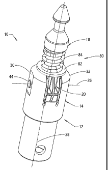
Referring to the accompanying drawings an embodiment of
the spearhead assembly 10 in accordance with the present
invention comprises a base 12 having an outer surface 14,
a slot 16 (see in particular Figure 7), a spear point 18
(shown in Figures 1-3) and a guard 20 (shown in Figures 1-
6). The slot 16 is formed in the base 12 and has an
opening 22 that opens onto the outer surface 14. The
spear point 18 has a proximal end located in the slot 16
and pivotally coupled about a pivot axis 26 to the base 12
to enable pivotal motion of the spear point 18. The spear
point 18 can pivot about the axis 26 between two angularly
spaced positions. These two positions are spaced by
approximately 180 and with reference to Figure 1
correspond to the spear point 18 being pivoted about axis
26 in an anti-clockwise direction to extend substantially
perpendicular to a longitudinal axis 28 and pointing into
the page, and a second position where the spear point 18
is pivoted in a clockwise direction about axis 26 to lie
perpendicular to the longitudinal axis 28 and pointing out
of the page.
CA 02627582 2007-11-27
WO 2006/128235 PCT/AU2006/000736
7
The guard 20 is coupled to the proximal end of the spear
point 18 and configured to at least partially occupy the
opening 22 when the spear point is in a location at or
between the aforementioned two spaced apart positions.
Consequently, the guard acts to minimise the risk of an
operator's hand or glove worn by the operator from being
pinched or caught in the slot 16 between the spear point
18 and the base 12 as the spear point 18 is pivoted
between the two positions. Thus embodiments of the spear
head assembly 10 and in particular guard 20 assist in
reducing the likelihood of injury or accident during
raising and lowering of a device to which the assembly 10
is attached, as well as during the coupling and decoupling
of the spear point assembly with an overshot.
With particular reference to Figures 7 and 8, the base 12
comprises a pair of spaced apart walls 30 and 32 between
which the slot 16 is defined, and the opening 22 is
formed. The walls 30 and 32 project from one end of a
spigot or a tube 34. The walls 30 and 32 each have a
generally semi-cylindrical outer surface which constitutes
a major portion of the outer surface 14 of the base 12;
and respective inner planar walls 31 and 33. An axial
channel 36 is formed in the tube 34 that communicates with
the slot 16. A concavely curved wall 38 is provided in
the base 12 between the walls 30 and 32, and onto which
the channel 36 opens. Holes 40 and 42 are formed in the
walls 30 and 32 respectively co-axial with the pivot axis
26. These holes receive a pivot pin 44 that also extends
through the proximal end of the spear point 18 and the
guard 20, coupling the spear point 18 to the base 12.
The opening 22 of the slot 16 can be considered as
comprising a plurality of contiguous lengths which are
shown most conveniently in Figure 8 as lengths 46, 48, 50,
52 and 54. These lengths correspond with edges formed
CA 02627582 2007-11-27
WO 2006/128235 PCT/AU2006/000736
8
between the outer peripheral surfaces of the walls 30 and
32 and their corresponding inner planar surfaces 31 and
33. In general, the lengths 46-54 trace a path in the
shape of an inverted U. It will be further observed that
a plane containing the length 46 is inclined (ie not
parallel) to a plane containing a length 48, which in turn
is not parallel to a plane containing a length 50, which
in turn is not parallel to a plane containing a length 52,
which lies in a plane not parallel to a plane containing a
length 54.
Barriers, in the form of upstanding lips 56 and 58 project
into the opening 22 between the walls 30 and 32. More
particularly, the lip 56 projects into the length 46 of
the opening, while the lip 58 projects into the length 54
of the opening. The lips 56 and 58 have respective
surfaces interior of the slot 16 that follow the curvature
of the concave wall 38. In this embodiment, the lips 56
and 58 extend upwardly only a relatively short distance
and terminate at a level short of the holes 40 and 42.
The lips 56 and 58 act to limit the pivotal motion of the
spear point 18 as well as further assist in the prevention
of pinching of an operators hand or glove. Passages 60
are formed between opposite lateral edges of each of the
lips 56 and 58 and the adjacent walls 30 and 32.
Referring to Figures 4-6, the guard 20 comprises a body 62
having opposite planar surfaces 64 and 66 that face the
inner planar walls 31 and 33 respectively, and a generally
arcuate radially outer surface, or side 68 between the
surfaces 64 and 66. A central recess or seat 70 is formed
in the body 62 for receiving the proximal end of the spear
point 18. A hole 72 is formed through the body 62 at the
bottom of the recess 70. The radial outer surface or side
68 can be considered as comprising three parallel radially
extending ribs or webs 74 and an axially extending rib 76.
The webs 74 and 76 lie in the vicinity of the opening 22
CA 02627582 2007-11-27
WO 2006/128235 PCT/AU2006/000736
9
irrespective of the pivotal position of the spear point
18. However depending on the particular pivotal location
of the spear point 18 the webs 74,76 may lie inside or
outside of the actual opening 22. Their actual position
relative to the opening is not per se critical to the
working of the invention. The function performed by the
webs 74,76 and moreover the guard 20 as a whole is to
substantially occupy the opening 22 to prevent pinching of
an operators hand or glove.
Channels or grooves 78 are formed between the webs 74,76,
which provide flow paths that communicate with the passage
60 and channel 36 so that drilling fluids or naturally
occurring fluids within a drill hole are able to flow
through the spearhead assembly 10.
By forming a small barb like projection or knob at the
proximal end of the spear point 18 and having an outer
diameter largely greater than the diameter of the hole 72,
an attachment mechanism is effectively formed to enable
the easy coupling of the guard 20 to the spear point 18.
The illustrated embodiment of the spearhead assembly 10
includes a spear point positioning system 80 of a type
described in International publication No. WO 2004/018831,
the contents of which is incorporated herein by way of
reference. Nevertheless, by way of brief explanation, the
spear point positioning system 80 operates to urge the
spear point 18 toward, and/or hold the spear point 18 in,
one of a plurality of angularly spaced positions. These
positions are characterised by the spear point 18
extending perpendicular to particular lengths 46-54 of the
opening 22 from which it extends. For example, with
reference to Figure 1, the spear point position system
operates to hold the spear point 18 in a position where it
extends perpendicular to the length 50 of the opening 22.
In Figure 2, the positioning system 80 holds the spear
CA 02627582 2007-11-27
WO 2006/128235 PCT/AU2006/000736
point 18 at a position perpendicular to a plane containing
the length 48 of the opening 22, and in Figure 3 the
positioning system holds the spear point 18 to extend
perpendicular to a plan containing the length 46 of the
5 opening 22. The positioning system 80 comprises a plate
in the form of a washer 82 retained on the spear point 18,
and a helical spring 84 also retained on the spear point
18 and acting to bias the washer 82 against the outer
surface 14 and more particularly, the lengths 46-54 of the
10 opening 22.
The positioning system 80 operates to provide a snap
action when the spear point 18 is pivoted between the
lengths 46-54 of the opening 22. More particularly, the
system 80 acts to bias or snap the spear point 18 to lie
perpendicular to the angularly closest length. For
example, consider the spear point 18 being moved from a
position shown in Figure 1 where it extends perpendicular
to the length 50, to the position shown in Figure 2 where
it extends perpendicular to the length 48. As the spear
point 18 is being pivoted about the axis 26, the system 80
will urge the spear point toward the perpendicular of
length 50 until it passes beyond the midway point to the
perpendicular to the length 48. Thus if one were to
release the force applied to the spear point 18 at that
time, the system 18 would act to snap the spear point 18
back to the position shown in Figure 1. However once the
spear point 18 is rotated past the midway point, the
system 80 acts to snap the spear point to a position
perpendicular to the length 48.
Now that embodiments of the present invention have been
described in detail it will be apparent to those skilled
in the relevant arts that numerous modifications and
various may be made without departing from the basic
inventive concepts. For example, the base 12 is described
and illustrated as including an axial passage 36. However
CA 02627582 2007-11-27
WO 2006/128235 PCT/AU2006/000736
11
in embodiments where the spear point is used in dry holes,
the passage 36 is not required. Also in these
circumstances, the channels 78 in the outer radial surface
of the guard 20 are not necessary. Further, the
configuration of the guard 20 is almost limitless. For
example with reference to the guard 20 as illustrated, it
may be modified by the inclusion of further axial ribs
parallel to the axial rib 76 so that the outer surface 68
takes a mesh like appearance. Indeed in an alternate
embodiment, a steel mesh or grid may be placed in the
channels or grooves 78. Further, the entire guard 20 may
be in the form of a wire mesh structure that is coupled to
the proximal end of the spear point 18. In an alternate
embodiment to that depicted in the drawings, the spear
point 18 and the guard 20 could be moulded or otherwise
constructed as a single piece.
It will be noted in particular from Figures 4 and 6 that
the outer most ribs or webs 74 comprise respective
straight edges or sides 79. In a further variation, it is
possible to laterally extend the straight edges or sides
79 so that when the spear point 18 is in alignment with
the longitudinal axis 28, the sides 79 lie marginally
inside an inner diameter of the drill pipe through which a
device attached to the spear point assembly 10 is tripped,
(ie the transverse distance between the lengths 79 on
opposite sides of the guard 20 is slightly smaller than
the inner diameter of the pipe). This has the effect of
self centering the spear point 18 when the assembly 10
enters and travels through the drill pipe. This obviates
the need for the positioning system 80 particularly
insofaras it operates to maintain the spear point 18 in
general alignment with the axis 28, and longitudinal axis
of the drill pipe. In this regard, it will be appreciated
that by dimensioning the length 79 as described above, the
spear point 18 will be maintained within a narrow arc from
the axis 28 when inside a drill pipe due to contact of the
CA 02627582 2007-11-27
WO 2006/128235 PCT/AU2006/000736
12
lengths 79 with the inner diameter of the drill pipe upon
pivoting of the guard 20 and the spear point 18 more than
only several degrees away from alignment with the axis 28.
All such variations and modifications together with others
that would be obvious to a person of ordinary skill in the
art are deemed to be within the scope of the present
invention the nature of which is to be determined from the
above description.