Note: Descriptions are shown in the official language in which they were submitted.
CA 02628072 2008-04-02
ANVIL POSITION DETECTOR
FOR A SURGICAL STAPLER
BACKGROUND
1. Technical field
The present disclosure relates to a jaw position detector for use with a
surgical
instrument. More particularly, the present disclosure relates to an anvil
position detector for use
in a surgical stapling instrument.
2. Background Of Related Art
Various surgical instruments are used in surgical procedures to grasp and
manipulate
tissue. These instruments may include devices having relatively movable jaw
structures such as,
for example, graspers, cutters, etc.
Other types of surgical instruments having movable jaw structure include
surgical
staplers. Surgical staplers typically incorporate a staple containing
cartridge and an anvil
member movably mounted relative to the staple containing cartridge. Tissue is
captured between
the anvil member and the staple containing cartridge and the stapler is
actuated to place one or
more rows of staples through the captured tissue and, in some cases, cut the
tissue between the
rows of staples. In order to properly staple the tissue, it is often necessary
that the anvil be
moved to a predetermined position relative to the remainder of the surgical
stapler and, in
particular, relative to the elongate member upon which the anvil is mounted.
- 1 -
CA 02628072 2008-04-02
In specific instances, it is desirable to orient the anvil member relative to
an elongate
member of the surgical instrument such that a longitudinal axis of the anvil
member is
substantially parallel to a longitudinal axis of the elongate member. This may
be necessary to
ensure that staple pockets associated with the anvil member are in a proper
position to fully
crimp the staples closed about the tissue being stapled. When performing a
procedure
endoscopically, it is often difficult to tell when the longitudinal axis of
the anvil member is in
proper alignment with respect to the longitudinal axis of the elongate member.
Thus, it would be desirable to provide a surgical instrument having an
indicator
mechanism capable of ensuring proper alignment of a jaw or anvil of the
surgical instrument
with the remainder of the surgical instrument. It would be further desirable
to provide an
indicator mechanism which provides a tactile indication of the proper
alignment. It would still
further be desirable to provide an indicator mechanism which provides an
audible indication of
the proper alignment.
SUMMARY
There is disclosed a surgical instrument incorporating a jaw position
detector. The
surgical instrument generally includes a handle and a support or elongate
member extending
distally from handle. The elongate member defines a first longitudinal axis. A
jaw assembly is
mounted on a distal end of the elongate member and includes a staple cartridge
and a movable
jaw or anvil mounted relative to the staple cartridge. The anvil defines a
second longitudinal
axis. A drive mechanism is provided to move the anvil between an open position
spaced apart
from the staple cartridge to a closed position substantially adjacent the
staple cartridge. A
- 2 -
CA 02628072 2008-04-02
position detector is associated with the drive mechanism and the anvil such
that position detector
provides an indication to an operator of the surgical instrument when the
first longitudinal axis is
in substantial alignment with the second longitudinal axis. The drive
mechanism includes a
driver movable within the elongate tubular member.
The position detector includes a notch formed in the jaw and a projection on
the driver
engageable with the notch on the jaw. The notch is a transverse notch formed
in the jaw and the
projection on the driver is a cross pin oriented transverse to the driver. In
one embodiment,
engagement of the cross pin with the notch provides a tactile indication to
the operator or user
that the first longitudinal axis is in substantial alignment with the second
longitudinal axis. In an
alternative embodiment, engagement of the cross pin with the notch provides an
audible
indication to the operator or user that the first longitudinal axis is in
substantial alignment with
the second longitudinal axis.
There is also provided an alternative surgical instrument incorporating a jaw
position
detector. The surgical instrument includes a support member having a first
longitudinal axis and
a jaw movably mounted on the support member and having a second longitudinal
axis. A drive
mechanism is movable over the support member and operable to move the jaw are
relative to the
support member. A position detector is associated with the jaw and a drive
mechanism such that
the position detector provides an indication to an operator of the surgical
instrument when the
first longitudinal axis is in substantial alignment with the second
longitudinal axis.
- 3 -
CA 02628072 2008-04-02
In one embodiment, the drive mechanism includes an outer tubular member
movable
over the support member and engageable with the jaw to move the jaw relative
to the support
member. The position detector includes a notch formed in the jaw and a
projection in the outer
tubular member. In one embodiment, the notch is a transverse notch formed in
the jaw and the
projection in the outer tubular member is an inwardly directed projection. In
one embodiment,
engagement of the projection with the notch provides a tactile indication to
the user or operator.
In an alternative embodiment, engagement of the projection with the notch
provides an audible
indication to the user or operator.
There is also disclosed an indicator for use with a jaw closure mechanism
incorporating a
threaded inner member and a threaded outer member. The indicator provides an
indication to a
user or operator when the threaded inner member is in a predetermined position
relative to the
threaded outer member. The position indicator includes a notch formed in the
threaded inner
member and a projection, engageable with the notch, formed in the threaded
outer member. In
one embodiment, engagement of the projection with the notch provides a tactile
indication to the
user or operator, while in an alternative embodiment, engagement of the
projection with the
notch provides an audible indication to the user or operator.
DESCRIPTION OF THE DRAWINGS
Various embodiments of the presently disclosed anvil position detector for use
in a
surgical stapler are disclosed herein with reference to the drawings, wherein:
FIG. 1 is a perspective view of a surgical stapler incorporating one
embodiment of an
anvil position detector for use with a surgical stapler:
-4.-
CA 02628072 2008-04-02
FIG. 2 is a side elevation view of the distal end of the surgical stapler of
FIG. 1;
FIG. 3 is a perspective view of the distal end of a drive bar of the surgical
stapler
incorporating part of the anvil position detector;
FIG. 4 is an end view of the distal end of the surgical stapler of FIG. 1;
FIG. 5 is a top view of the distal end of the surgical stapler of FIG. 1;
FIG. 6 is a side elevation view of the distal end of the surgical stapler of
FIG. 1
positioned about tissue;
FIG. 7 is a side elevation view of the distal end of the surgical stapler of
FIG. 1 with the
tissue captured between the jaws and the anvil position detector engaged;
FIG. 8 is a perspective view of a surgical stapler incorporating an
alternative embodiment
of an anvil position detector;
FIG. 9 is a side elevation view of the distal end of the surgical stapler of
FIG. 8;
FIG. 10 is a cross-sectional view of the distal end of a drive tube of the
surgical stapler of
FIG. 8 incorporating part of the anvil position detector;
FIG. 11 is an end view of the distal end of the surgical stapler of FIG. 8;
FIG. 12 is a top view of the distal end of the surgical stapler of FIG. 8;
FIG. 13 is a side view of the distal end of the surgical stapler of FIG. 8
positioned about
tissue;
FIG. 14 is a side elevation view of the distal end of the surgical stapler of
FIG. 8 with the
tissue captured between the jaws and the anvil position detector engaged;
FIG. 15 is a cross-sectional view of an alternate embodiment of an anvil
position detector
for use with the jaw closure mechanism of a surgical stapler;
- 5 -
CA 02628072 2008-04-02
FIG. 16 is a cross-sectional view of the anvil position detector of FIG. 15 in
the engaged
position, and
FIG. 17 is a perspective view of the distal end of a component of an anvil
position
detector.
DETAILED DESCRIPTION OF EMBODIMENTS
Embodiments of the presently disclosed anvil position detector for use in
surgical staplers
will now be described in detail with reference to the drawings wherein like
numerals designate
identical or corresponding elements in each of the several views. As is common
in the art, the
term 'proximal" refers to that part or component closer to the user or
operator, i.e. surgeon or
physician, while the term "distal" refers to that part or component further
away from the user.
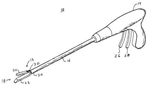
Referring to FIG. 1, there is illustrated as surgical stapler 10 incorporating
one
embodiment of an anvil position detector 12. Surgical stapler 10 is includes a
handle 14 and an
elongated tubular member 16 extending distally from handle 14. A jaw assembly
18 is provided
on a distal end 20 of elongate tubular member 16. Jaw assembly 18 includes a
staple cartridge
22 and an anvil 24 which is mounted for movement relative to staple cartridge
22. Staple
cartridge 22 is of the type containing a plurality of staples (not shown)
which are provided to be
driven through tissue and into anvil 24 for crimping about the tissue. Staple
cartridge 22 may be
permanently mounted to elongate tubular member 16 or may be removable and
therefore
replaceable with a new staple cartridge 22. Anvil 24 is movable between an
open position
- 6 -
CA 02628072 2008-04-02
spaced apart from staple cartridge 22 to a closed position substantially
adjacent staple cartridge
22.
Surgical stapler 10 additionally includes a first trigger 26 and a second
trigger 28
movably mounted on handle 14. First trigger 26 is provided to move anvil 24
between the open
and closed positions. Actuation of first trigger 26 operates to move a driver
30 longitudinally
relative to elongate tubular member 16 so as to cam anvil 24 from the open
position to the closed
position. Actuation of second trigger 28 operates to eject staples from staple
cartridge 22
through tissue and into anvil 24 for crimping about the tissue.
Referring now to FIG. 2, as noted above, staple cartridge 22 is mounted on
elongate
tubular member 14. Elongate tubular member 14 has a first longitudinal axis A-
A. Specifically,
a proximal end 32 is mounted to distal end 20 of elongate tubular member 14. A
proximal end
32 of anvil 24 is movably mounted to proximal end 32 of staple cartridge 22 at
pivot 36. In
order to move anvil 24 between the open and closed positions, a cross pin 38
is provided on
driver 30 and is engageable with an angled edge 40 at proximal end 34 of anvil
24. As cross pin
38 is driven against angled edge 40, anvil 24 is moved from the open to the
closed position.
Referring for the moment to FIG. 3, cross pin 38 is transversely mounted
through a distal
end of 42 of driver 30. Distal end 42 of driver 30 may additionally include an
arcuate tissue stop
44 provided to prevent tissues from being pinched between anvil 24 and staple
cartridge 22.
- 7 -
CA 02628072 2008-04-02
Referring back to FIG. 2, and as noted hereinabove, surgical stapler 10
includes anvil
position detector 12 which is provided to give an indication to the operator
of surgical stapler 10
when anvil 24 is in the proper position relative to elongate tubular member
14. Anvil position
detector 12 includes a cross notch 46 formed in anvil 24 which cooperates with
cross pin 38 on
driver 30. Specifically, as anvil 24 is moved toward the closed position cross
pin 38 moves
toward and engages cross notch 46. When cross pin 38 engages cross notch 46,
it does so in
such a manner as to provide a tactile indication, such as the feeling of two
parts snapping
together, to the operator of surgical stapler 10. Additionally, the engagement
of cross pin 38
with cross notch 46 may also provide an audible indication to the operator of
surgical stapler 10
that cross pin 38 has engaged cross notch 46 and anvil 24 is properly oriented
relative to elongate
tubular member 14.
Referring now to FIGS. 4 through 7, and initially with respect to FIGS. 4 and
5, in the
initial position, anvil 24 is in the open position spaced apart from staple
cartridge 22 and driver
30, containing cross pin 38, is in a proximal position relative to cross notch
46 in anvil 24.
As best shown in the FIGS. 6 and 7, in use, jaw assembly 18 is positioned
about a tubular
tissue section T to be stapled. It should be noted that, while the discussion
of anvil position
detector 12 is being given relative to a surgical stapler 10 and an anvil 24,
the operation of anvil
position detector 12 is equally applicable to other surgical instruments
having tissue engaging
jaw structures such as, for example, graspers, cutters, etc. Once tissue T has
been properly
positioned within jaw assembly 18, first trigger 26 (FIG. 1) is actuated to
move driver 30 distally
relative to elongate tubular member 14. As driver 30 moves distally, cross pin
38 engages
- 8 -
CA 02628072 2008-04-02
angled edge 40 of anvil 24 and cams anvil 24 to the closed position relative
to staple cartridge
22.
It should be noted that the location of cross notch 46 is configured to
correspond to the
situation where a longitudinal axis B-B of anvil 24 is parallel to
longitudinal axis A-A of
elongate tubular member 14. Specifically, cross pin 38 engages cross notch 46
at the point
where longitudinal axis B-B is parallel to longitudinal axis A-A of elongate
tubular member 14.
As cross pin 38 engages cross notch 46, cross pin 38 snaps into engagement
with cross notch 46
giving both a tactile and audible indication to the operator of surgical
stapler 10 that anvil 24 is
in the proper orientation relative to elongate tubular member 14. Thus, cross
pin 38, in
combination with cross notch 46, forms an anvil position detector enabling the
operator of
surgical instrument 10 to be confident that the anvil 24 is in the proper
position to crimps staples.
As shown, staple cartridge 22 may undergo a certain amount of deflection D due
to the capture
of tissue T between anvil 24 and staple cartridge 22. This has been found not
to affect the
efficacy of staples applied to tissue T and crimped in anvil 24. As such, it
is not critical to the
stapling of tissue T to exactly orient staple cartridge 22 relative to
elongate tubular member 14.
Referring now to FIG. 8, there is disclosed an alternative surgical stapler 50
incorporating
an alternative mechanism for indicating the proper position of an anvil
associated with surgical
stapler 50. Surgical stapler 50 generally includes a handle 52 having an inner
member 54
extending distally from handle 52. A jaw assembly 56 is mounted on a distal
end 58 of inner
member 54. Jaw assembly 56 includes an anvil 60 and a staple cartridge 62. An
outer tubular
member 64 is mounted for longitudinal movement relative to inner member 54 and
handle 52.
- 9 -
CA 02628072 2008-04-02
Outer tubular member 64 is provided to cam anvil 60 from an open position
spaced apart from
staple cartridge 62 to a closed position substantially adjacent to staple
cartridge 62. A first
trigger 66 is movably mounted on handle 52 and operates to move outer tubular
member 64
longitudinally relative to inner member 54. A second trigger 68 is provided to
eject staples (not
shown) from staple cartridge 62 and into anvil 60 in order to staple tissue
captured there
between. As noted hereinabove, surgical stapler 50 incorporates an alternative
anvil position
detector 70 for providing an indication to the operator of surgical stapler 50
when anvil 60 has
been properly oriented relative to the remainder of surgical stapler 50.
As best shown in FIG. 9, a proximal end 72 of staple cartridge 62 is affixed
to distal end
58 of inner member 54. Anvil 60 is movably mounted with respect to staple
cartridge 62. A
proximal end 74 of anvil 60 is pivotally mounted to staple cartridge 62 at
pivot 76. In order to
move anvil 60 between the open and closed positions, anvil 60 includes an
angled edge 78 at
proximal end 74 of anvil 60. Outer tubular member 64 is provided with a distal
or camming
edge 80 which is configured to engage angled edge 78 to move anvil 60 from the
open to the
closed position. As noted hereinabove, surgical stapler 50 includes an anvil
position detector 70
to give the operator an indication of the proper positioning of anvil 60.
Similar to anvil 24
described hereinabove, anvil 60 includes a cross notch 82.
Referring for the moment to FIG. 10, and as noted hereinabove, outer tubular
member 64
is hollow for movement over inner member 54. Outer tubular member 64 includes
a distal end
84 and an inwardly directed projection 86, which forms part of anvil position
detector 70, and
which is configured to engage cross notch 82 in anvil 60 (FIG. 9).
-10-
CA 02628072 2008-04-02
Referring now to FIGS. 11 and 12, in the initial position, anvil 60 is in the
open position
spaced apart from staple cartridge 62 (FIG. 11). Outer tubular member 64,
including camming
edge 80, is in a proximal position relative to angled edge 78 on anvil 60
(FIG. 12). As best
shown in FIG. 13, anvil 60 and staple cartridge 62 are initially positioned
about a tubular tissue
section T. Actuation of first trigger 66 (FIG. 8) causes outer tubular member
64 to move distally
forcing camming edge 80 into engagement with angled edge 78. Engagement of
camming edge
80 with angled edge 78 moves anvil 60 from the open position to the closed
position relative to
staple cartridge 62 as best shown in FIG. 14. As with surgical stapler 10
described hereinabove,
engagement of anvil position detector 70, including cross notch 82 and inward
projection 86, is
configured to correspond to the condition where a longitudinal axis E-E of
anvil six the is in the
proper orientation, i.e. approximately parallel to, a longitudinal axis C-C of
inner member 54.
As inward projection 86 on outer tubular the member 64 engages cross notch 82
in anvil 60, the
user is provided with an audible and tactile indication that anvil 60 is in
proper alignment with
respect to the remainder of surgical stapler 50. As shown, and as noted
hereinabove, a certain
amount of deflection D2 may occur in staple cartridge 62 without affecting the
ability of anvil 62
properly crimps staples about tissue section T.
Referring now to FIGS. 15 and 16, there is disclosed a further alternative
embodiment of
an anvil position indicator 90. Anvil position indicator 90 is configured for
use with an anvil
closure mechanism that incorporates interengaging threaded members such as,
for example, a
jackscrew etc. An inner member 92 includes threads 94 and a hollow outer
member 96 includes
corresponding threads 98. Inner member 92 is provided with a notch 100 which
is formed as an
-11-
CA 02628072 2008-04-02
enlarged or deepened area in threads 94. Similarly, outer member 96 includes
an enlarged
projection on inner threads 98 which is configured to engage notch 100. As
with prior
embodiments, engagement of projection 102 with notch 100 corresponds to the
condition where
a jaw and handle of a surgical instrument are in proper orientation for use.
Likewise, similar to
that disclosed hereinabove, engagement of projection 102 with notch 100
provides both an
audible and tactile indication to the user that the proper alignment has been
obtained.
Referring finally to FIG. 17, there is illustrated a distal end 110 of a
hollow outer member
112. As with outer member 96 above, inner threads 114 include an enlarged
projection or
enlarged distal most thread 116. Distal end 110 of outer member 112 includes
an L-shaped
cutout 118 which allows distal end 110 to flex or act as a sprung member
preventing enlarged
distal most thread 116 from jamming with threads on a corresponding inner
member until
enlarged distal most thread 116 drops into a corresponding notch in the inner
member.
While the above described anvil position indicator mechanisms have been
disclosed as
giving audible, and/or, tactile indications to the user of the proper
alignment of a jaw associated
with a surgical instrument, it is also within the contemplated scope of the
invention to provide an
audible or visual signal via electrical means to the user. This can be
accomplished by a
electrically insulating the disclosed March from the remainder of the anvil
material and
electrically insulating the disclosed projection from the remainder of the
drive mechanism used
to close the anvil member. The notch and projection may form contacts which,
when engaged,
provide an electrical signal to a mechanism associated with a surgical
instrument which in turn
- 12 -
CA 02628072 2014-10-27
can provide a visual and/or audible indication to the user that the notch and
projection have been properly
engaged. In the alternative, a simple contact switch can be used.
It will be understood that various modifications may be made to the
embodiments disclosed
herein. For example, the materials used in the engaging components may be the
same materials or
dissimilar materials so as to enhance the audible and tactile signals given to
the user. Further, the
engagement of a projection into a notch may be provided in other jaw closure
mechanism so as to give the
operator an audible and tactile indication of proper functioning of the
surgical instrument. Additionally,
the disclosed position detectors may be used in other jaw structures such as,
for example, tissue graspers,
tissue cutters, clip appliers, etc. Therefore, the above description should
not be construed as limiting, but
merely as exemplifications of particular embodiments. The scope of the claims
should not be limited by
the preferred embodiments set forth herein, but should be given the broadest
interpretation consistent with
the description as a whole.
-13-