Note: Descriptions are shown in the official language in which they were submitted.
CA 02628218 2008-03-28
AN IMPROVED STRUCTURE OF AUTOMATIC WOOD
PLANER
BACKGROUND OF INVENTION
1. Field of the Invention
The present invention relates generally to an automatic wood planer,
and more particularly to an innovative one which enables the lift
assembly of the cutter shaft to be implemented by adapting two front
columns with two rotary supports.
2. Description of Related Art
An automatic wood planer is a woodworking machine used for
automatically guiding, planing and leveling of timber.
A typical automatic wood planer is designed in such a manner that the
cutter shaft mechanism is assembled onto a preset location of lifting
footstock on the machine; said lifting footstock is supported by four
columns at four corners, enabling it to slide along four columns when
adjusting the planing height; however, it is found from actual application
that the footstock of automatic wood planer is expanded upwards, thus
bringing about a bulky and cumbersome structure; moreover, higher
fabrication cost and sales price will impair its market competitiveness;
from the perspective of mechanical operation of the typical automatic
wood planer with four columns, screwing clearance exists between the
columns and lifting footstock, resulting in obvious error during height
adjustment of the lifting footstock.
1
CA 02628218 2008-03-28
Thus, to overcome the aforementioned problems of the prior art, it
would be an advancement if the art to provide an improved structure that
can significantly improve the efficacy.
Therefore, the inventor has provided the present invention of
practicability after deliberate design and evaluation based on years of
experience in the production, development and design of related products.
SUMMARY OF THE INVENTION
1. The present structure of two front columns and two rotary supports
could save more components, reduce the volume and fabrication
cost with improved economic efficiency and applicability.
2. With the improved structure, the screwing portion for adjustment of
the cutter shaft will be reduced, resulting in little error and
improved adjustment accuracy.
Although the invention has been explained in relation to its preferred
embodiment, it is to be understood that many other possible modifications
and variations can be made without departing from the spirit and scope of
the invention as hereinafter claimed.
BRIEF DESCRIPTION OF THE DRAWINGS
FIG. 1 shows an assembled perspective view of the present invention.
FIG. 2 shows a partially enlarged view of the present invention.
FIG. 3 shows a plain lateral view of the planning operation of the present
invention.
2
CA 02628218 2008-03-28
FIG. 4 shows another plain lateral view of the planning operation of the
present invention.
FIG. 5 shows a view of height adjustment of cutter shaft of the present
invention.
FIG. 6 shows an exploded perspective view of the reinforced rod of the
present invention.
FIG. 7 shows an assembled sectional view of reinforced rod of the present
invention.
io DETAILED DESCRIPTION OF THE INVENTION
The features and the advantages of the present invention will be more
readily understood upon a thoughtful deliberation of the following
detailed description of a preferred embodiment of the present invention
with reference to the accompanying drawings.
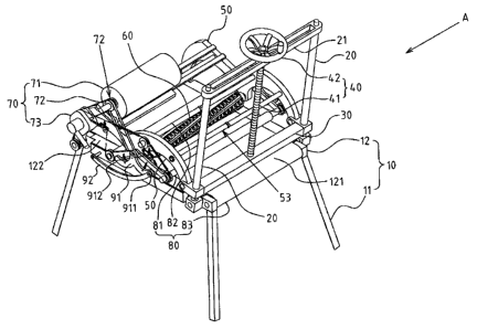
FIGS. 1-3 depict preferred embodiments of an automatic wood
planer of the present invention, which, however, are provided for only
explanatory purpose for patent claims. Said automatic wood planer A
comprising:
a main body 10, including: supporting portion 11 and feed table 12;
the feed table 12 is provided with an input end 121 and an output end 122;
two front columns 20, arranged separately at both sides of input end
121 of the feed table 12 of the main body 10; the bottom of two front
columns 20 is screwed with the feed table 12 for a swinging state, and the
top of two front columns 20 is connected via a cross bracket 21;
a lifting seat 30, transversely bridged between two front columns 20
3
CA 02628218 2008-03-28
in a sliding state;
a brake unit 40, used to control the sliding state of the lifting seat 30;
two rotary supports 50, obliquely assembled between the lifting seat
30 and the output end 122 of the feed table 12; said rotary support 50 is
available with pin joint end 51, which could be screwed at both sides of
the output end 122 of the feed table 12, or screwed on the protruding
framework of the feed table 12; the other end of the rotary support 50 is a
swinging end 52 that's connected at both sides of the lifting seat 30; said
rotary support 50 is also of a prefabricated structure;
a cutter shaft 60, assembled at central section between pin joint end
51 and swinging end 52 of two rotary supports 50, so that the bottom of
the cutter shaft 60 is placed oppositely to the feed table 12;
a cutter shaft's brake unit70, used to drive the cutter shaft 60 for
rotation;
a feed unit 80, including at least a front roller 81 and a rear roller 82,
which are separately assembled at the bottom of the rotary support 50, and
transversely positioned at interval with the cutter shaft 60.
Said brake unit 40 comprises a screw 41 and a rotary table 42 fixed
onto top of the screw 41; then, the cross bracket 21 at top of two front
columns 20 is provided with a screw hole 22 (shown in FIG. 3) for the
screw 41; the bottom of the screw 41 could be rotarily connected to the
lifting seat 30, so the rotary table 42 could be operated to drive the
forward and reverse rotation of the screw 41, thus enabling the sliding of
the lifting seat 30.
Said cutter shaft's brake unit7O comprises a motor 71, drive unit 72
4
CA 02628218 2008-03-28
(belt and belt wheel, or chain and chain wheel) and a gearbox 73, of
which the motor 71 is assembled at top of two rotary supports 50 adjacent
to the pin joint end 51; said drive unit 72 is placed laterally onto the
rotary
support 50, and then connected with the motor 71, cutter shaft 60 and
front and rear rollers 81, 82, so the motor 71 could drive simultaneously
the cutter shaft 60 and front/ rear rollers 81, 82; the feedstock could be
shifted with forward drive of the front and rear rollers 81, 82. Moreover,
said feed unit 80 comprises a conveyor belt 83, which is assembled onto
the feed table 12 for recycling operation; the conveyor belt 83 could also
1o be driven by the cutter shaft's brake unit70; additionally, the feed unit
80
could drive forwardly the feedstock via the conveyor belt 83. In such
case, the front and rear rollers 81, 82 could just press the feedstock
without being driven by the cutter shaft's brake unit7O. (Note: this view
shows that the front and rear rollers 81, 82 and conveyor belt 83 are
driven by the cutter shaft's brake unit7O simultaneously).
A swinging rack 91 and traction frame 92 are arranged between the
swinging end 52 of two rotary supports 50 and the feed table 12; the
swinging rack 91 is provided with front and rear extensions 911, 912,
which are available with stoppers 913, 914; both ends of the traction
frame 92 are separately connected to the front extension 911 of the
swinging rack 91 and the feed table 12, so that the front and rear rollers
81, 82 are separately adapted with the rotary support 50 and swinging
rack 91 via front and rear cantilever 811, 821; the front and rear
cantilevers 811, 821 are separately supported on the stopper 913, 914 of
the front and rear extension 911, 912 of the swinging rack 91;
5
CA 02628218 2008-03-28
furthermore, an elastic meinber 93 (a spring) is arranged between the
front and rear extensions 911, 912 and front and rear cantilevers 811, 821.
A plurality of reinforced rods 53 is arranged between two rotary
supports 50. Referring to FIGS. 6, 7, the reinforced rod 53 comprises the
first and second rods 531, 532, where stud 533 and screw hole 534 are
arranged at the coupling end of the first and second rods 531, 532; the
stud 533 is provided with nut 535, while the stud 536 is placed externally
onto the first and second rods 531, 532, and located via the nut onto two
rotary supports 50; the reinforced rod 53 is used to make up the spacing
error between two rotary supports 50 since the coupling portion allows for
slight adjustment of the length, helping to realize optimum connection
and reinforcement.
Based upon above-specified structural design, the present invention is
operated as follows:
Referring to FIGS. 4, 5, when it is intended to adjust the height of said
cutter shaft 60, the rotary table 42 of the brake unit 40 could be rotated
forwardly or reversely; the rotation of the rotary table 42 will drive the
screw 41 to pass through the screw hole 22 of the cross bracket 21, so the
motion of screw 41 will lead to vertical shift, and then drive the lifting
seat 30 to slide along two front columns 20 (shown by arrow L1); with the
slide of the lifting seat 30, the swinging end 52 of two rotary supports 50
will be driven for vertical swinging; the cutter shaft 60 between pin joint
end 51 and swinging end 52 of two rotary supports 50 could lift flexibly
for adjusting the planing depth; moreover, when the lifting seat 30 is
6
CA 02628218 2008-03-28
activated to drive the rotary support 50 for oblique swinging, the swinging
end 52 will generate lateral displacement. Correspondingly, a swinging
structure may be designed between the bottom of two front columns 20
and the feed table 12, allowing for smooth motion of the lifting seat 30.
On the other hand, the traction frame 92 and swinging rack 91 could
be arranged to make the front and rear rollers 81, 82 press horizontally the
feedstock during oblique swinging of two rotary supports 50. Referring to
FIG. 5, when the swinging end 52 of the rotary support 50 is driven by the
lifting seat 30 to shift upwards, both ends of the traction frame 92 is
separately connected to the front extension 911 of the swinging rack 91
and the feed table 12, the front and rear rollers 81, 82 will press
horizontally the feedstock without being affected by the oblique swinging
of the rotary support 50 (since the front and rear cantilevers 811, 821 of
fiont and rear rollers 81, 82 are supported by the front and rear extensions
911, 912 of the swinging rack 91, and the front and rear extensions 911,
912 are connected to the front and rear cantilevers 81 l, 821 via an elastic
member 93).
Referring to FIGS. 3, 4, feedstock B is fed from the input end 121 of the
feed table 12, then guided and rolled through the conveyor belt 83 and
front roller 81 of the feed unit 80, enabling the smooth planning of the
cutter shaft 60; then, the feedstock B will be rolled by the rear roller 82
and output via the conveyor belt 83 outside of the feed table 12.
7