Note: Descriptions are shown in the official language in which they were submitted.
CA 02628231 2008-05-01
WO 2007/056248 PCT/US2006/043136
LASER TRIMMED DRIP FREE BOTTLE
CROSS-REFERENCE TO RELATED APPLICATIONS
[0001] This application claims priority to, and any other benefit of, US
Provisional Patent
Application No. 60/733,626 filed November 4, 2005, the entirety of which is
incorporated
herein, by reference.
BACKGROUND
[0002] Liquid consumer goods, such as cooking oils, tend to have droplets of
the liquid drip
over the lip of the pour spout when poured from the container. The drips are
not only messy,
but also make the outside of the bottle sticky, which could lead to
contamination. One
method that has been used to make drip free bottles is to create a drip free
lip on the bottle
during the injection molding process. This method is relatively expensive
because of the
amount of extra plastic that must be used when the entire finish of the bottle
is injection
molded. Another method for making drip free bottles involves separately
forming a bottle
and a drip free injection molded fitment and then joining the separately made
bottle and
fitment to form a drip free bottle. This method, however, is costly because
the drip free
fitment and the bottle are two separate articles that must be joined together.
Finally, drip free
lips have also been formed on bottles mechanically, using frictional heating
and physically
contacting the bottle surface. This method also has drawbacks, both in
maintenance costs as
well as the risk of contamination when the bottle lip comes into physical
contact with the
machinery.
[0003] Accordingly, a new method is needed to form drip free bottles. The new
method
should be able to be used with preformed bottles, eliminating the need for
extra plastic in the
injection molding process, eliminating the need to join two separate pieces to
form the bottle,
and eliminating the need to pliysically contact the bottle, which in turn
decreases machinery
maintenance costs and risk of contamination.
SUMMARY OF THE INVENTION
> .~., .
[0004] Provided herein are methods for forming drip-free pouring surfaces and
the pouring
surfaces formed by_those rrietliods. In one method, the edge of a pouring
surface is heated,
CA 02628231 2008-05-01
WO 2007/056248 PCT/US2006/043136
without physically contacting the surface, to form a drip-free profile. This
method may be
used when the pouring surface already has an edge, or when the edge of the
pouring surface
is formed during the heating process. The heat source may be virtually any
source that
provides sufficient energy to melt the edge of the pouring surface and form
the drip-free
profile. Some sources of heat include lasers, convection sources, infrared
sources,
microwave sources, superheated steam, electromagnetic radiation sources,
sources of flame,
and combinations thereof. In one embodiment, the heat source is a laser. The
pouring
surface may be any polymeric material that forms the drip-free profile when
heated according
to the inethods provided herein. Some polymers that may be used include, but
are not limited
to polyolefins, PET, HDPE, PVC, polystyrene, nylon, polypropylene and so
forth.
[0005] Also provided are containers having the drip-free pouring surfaces
described herein.
In one embodiment, the container includes a reservoir for storing a fluid, and
at least one
pouring surface forming an opening through which fluid may be poured from the
reservoir,
and wherein the pouring surface has a drip-free profile formed by the methods
described
herein.
BRIEF DESCRIPTION OF THE DRAWINGS
[0006] Figure 1 depicts a cross-sectional comparison of (a) a drip free pour
spout as formed
using an injection molding or frictional heating/contact process and (b) an
exemplary drip
free pour spout formed using the methods described herein.
[0007] Figure 2 shows the actual profile of the exenlplary drip free bottle
lip made using the
methods described herein.
[0008] Figure 3 shows five exemplary flange profiles that could be used with
the methods
described herein.
[0009] Figure 4 shows an exemplary bottle finish with a horizontal flange.
[0010] Figure 5 shows an exemplary embodiment wherein the drip free lip is
created on a
vertical wall of the bottle.
2
CA 02628231 2008-05-01
WO 2007/056248 PCT/US2006/043136
DETAILED DESCRIPTION OF THE INVENTION
[0011] Provided herein are drip free bottles having pouring surfaces that are
resistant to
dripping, as well'as methods of making bottles and pour spouts with drip-free
profiles. The
methods and the bottles made by those methods exhibit good drip free
properties while being
less expensive to produce than drip free bottles made by other methods. The
methods for
malcing a drip free pour surfaces may be used with any plastic bottles that
are commonly used
for household or industrial liquids or solutions that are typically poured
from the bottle. The
drip-free profiles formed using the methods described herein are particularly
useful for such
things as oils, such as cooking oils, which tend to drip when poured from a
bottle.
Representative plastics include, but are not limited to polyolefins, PET,
HDPE, PVC,
polystyrene, nylon, polypropylene and so forth.
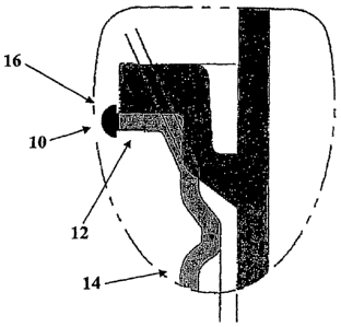
[0012] The geometry of the pour spout edge 10 created by the laser cut is
mushroom shaped
in cross section, which is shown at the end of an approximately horizontal
flange 12 from
neck 14 in Figures 1, and 2. This geometry uses the surface tension of the oil
or other
viscous liquid to pull the oil back inside the bottle instead of dripping or
running down the
outside of the bottle. The geometry of the laser trimmed bottle is compared to
that of the drip
free lip that is formed on during the injection molding process in Figure 1.
Using the
methods described herein, the laser, or other heat source, melts the plastic
creating a
mushroom shape at the end of the flange as shown in Figures 1 and 2. Perhaps
only a portion
of the inushroom-shaped pour spout edge 10 is needed to provide reduced
dripping, e.g., a
lower or outside portion of the edge 10 contacting the oil or other fluid.
Figure 3 shows
several flange profiles that may be used with the methods described herein.
Figure 4 shows a
representative bottle top with a horizontal flange. Detail A of figure 4
illustrates both the drip
free pour spout and one embodiment of the drip free pour spout and a
representative fitment
16. In another exemplary embodiment, the drip free lip may be formed on a
vertical wall of
the bottle, thus eliminating the need for a horizontal flange. Figure 5 shows
a bottle with no
horizontal flange that may be used in accordance with the methods described
herein. In
another embodiment, the drip free lip could be formed on a flange at any angle
between 90
degrees and 0 degrees off the center line of the bottle. In another
embodiment, the drip free
lip may be formed on a pour spout that has U-shaped, C-shaped or V-shaped pour
spout, such
as those used with a gravity flow back channel.
3
CA 02628231 2008-05-01
WO 2007/056248 PCT/US2006/043136
[0013] Using the-inethods described herein, the edge of a pouring surface is
heated, without
physically contacting the surface, to form a drip-free profile. This method
may be used when
the pouring surface already has an edge, or when the edge of the pouring
surface is formed
during the heating process. The heat source may be virtually any source that
provides
sufficient energy to melt the edge of the pouring surface and form the drip-
free profile. Some
sources of heat include lasers, convection sources, infrared sources,
microwave sources,
superheated steam, electromagnetic radiation sources, sources of flame, and
combinations
thereof. In one embodiment, the heat source is a laser. For simplification,
the methods
described herein will be referred to in terms of laser cutting. However, it
should be
recognized that other heating methods, including convection sources, infrared
sources,
microwave sources, superheated steam, electromagnetic radiation sources,
sources of flame,
and combinations thereof, may be used instead of laser trimming and are
encompassed by the
methods described herein.
[0014] The trimming metllod for making a drip free bottle provided herein has
several
advantages over other known methods for making drip free bottles. First, there
is no physical
contact with the bottle therefore reduced risk of product contamination. By no
physical
contact, it is meant that there are no parts that mechanically contact the
bottle to form the drip
free profile. There are no machine parts that wear during operation due to
physically
reforming the bottle lip. Trimming a horizontal flange eliminates the need to
rotate the bottle
during laser trimming; the laser beam or other heat source is electrically
steered. Also, the
amount of plastic required is less for a blow molded finish than for an
injection molded bottle
finish making the bottle less expensive.
[0015] The laser iused can be any laser that has sufficient power and power
density to melt a
bottle thickness of the polymer used to form the bottle. In one embodiment, a
CO2 laser is
used, however, in other embodiments, different lasers may be used provided the
power
density of the laser is sufficient to cut the plastic of the pouring surface.
The polymer may be
selected from PET, HDPE, polyethylene, polystyrene, polypropylene, PVC, and so
fortli. For
an exemplary PET bottle that is thirty-five thousands thick, the laser and
power would be
chosen such that the laser is capable of trimming the PET. One skilled in the
art would be
able to select a laser of appropriate wavelength and power to trim a selected
plastic of known
thickness.
4
CA 02628231 2008-05-01
WO 2007/056248 PCT/US2006/043136
[0016] Laser trimming is well-known in the art and the various embodiments of
the present
invention may be implemented using known tecliniques. Briefly, the following
exemplary
method may be used to form the exemplary drip free lip on a horizontal flange
according to
the present invention: a laser having sufficient power to melt the plastic of
interest, is
directed to a steering mirror mounted above the center line of the bottle to
be trimmed; the
laser beam is focused such that the maximum power density is at the flange;
and the mirror,
which may be driven by servo motors, is used to steer the laser beam around
the bottle,
trimming the flange all of the way around the bottle to form the drip free lip
described herein.
No physical contact with the drip free lip is necessary; the mushroom-shaped
profile of
Figures 1-2 is a natural result of using an appropriate laser to trim the
horizontal flange 12.
[0017] In another embodiment, the drip-free lip could be formed using any type
of non-
contact heat, such as a laser, a burner or other source of flame, a convection
source, an
infrared source, a microwave source, superheated steam, radiant energy,
electromagnetic
radiation or combinations thereof.
[0018] In an exemplary vertical cut embodiment, the laser may be directed to a
mirror
mounted above the center line of the bottle. The laser may be focused to have
maximum
power density at the surface of the bottle that is to be trimmed. The mirror
may be used to
steer the beam around the bottle, trimming the plastic and forming the drip
free lip described
herein.
[0019] The exemplary drip free bottles described herein are particularly
useful for cooking
oils, but may also be useful for other edible liquids including syrups,
sauces, drinks, and so
forth, as well as non-edible liquids, including but not limited to cleaning
products such as
laundry detergents and fabric softeners, household or automotive cleaners;
personal care
items, such as shampoos, conditioners, moisturizers, cleansers; and other
applications, such
as pesticides, herbicides, plant foods and fertilizers.
[0020] The specific embodiments described herein are for illustrative purpose
and are not
meant to limit the scope of this invention as described in the claims.