Note: Descriptions are shown in the official language in which they were submitted.
CA 02628331 2008-05-02
WO 2007/055922 PCT/US2006/041840
ONE WAY VALVE ASSEMBLY
1
CA 02628331 2008-05-02
WO 2007/055922 PCT/US2006/041840
BACKGROUND OF THE INVENTION
The present in~ Tention is directed to a one way valve assembly for
dispensing a sterile flowable substance while preventing any backflow of
contaminants into the source of the flowable substance. The valve assembly
includes a valve body enclosed by a pressure displaceable flexible member or
elastomeric member for effecting the passage of the flowable substance to a
controllable outlet while preventing any backflow to the source of the
flowable
substance after dispensing individual portions of the flowable substance.
In the past, to maintain the flowable substance free of contaminants,
preservatives have been mixed in the flowable substance in the container from
which it is to be dispensed. The use of preservatives is an added expense and
tends to limit the effectiveness of the flowable substance, particularly when
the
flowable substance is a pharmaceutical such as an eye care solution or it is a
food stuff.
Another consideration is the ability of the valve assembly to deliver a
selected amount to the outlet without causing any damage to the user, such as
when applying an eye care solution directly into the eye.
2
CA 02628331 2008-05-02
WO 2007/055922 PCT/US2006/041840
In recent years, flexible membranes have been used to control the flow of the
flowable substance to the valve assembly outlet while preventing any backflow
to the source of the floYjable substance, however, it has been difficult to
provide
an effective procedure for manufacturing the valve assembly and limiting its
costs.
SUNIlVIAI2Y OF THE INVENTION
Therefore, the primary object of the present invention is to provide a
valve assembly for conveying a flowable substance from a closed source, such
as a collapsible container while preventing any backflow of contaminants
through the valve assembly into the source of the flowable substance after a
portion of the substance has been dispensed.
The collapsible container can be a bellows type, a tube, an internal bag or
other type of collapsible form designed to dispense practically all of its
contents. The container has a normally closed controllable outlet surface for
dispensing a flow of the flowable substance out of the valve assembly. The
container is in sealed contact with the valve assembly so that its contents do
not
receive any contaminants when the flowable substance is dispensed.
3
CA 02628331 2008-05-02
WO 2007/055922 PCT/US2006/041840
Dispensation of the flowable substance is effected by applying pressu_-e
to the container so that its contents flow to the valve assembly. The contents
may be a pharmaceuticai, such as an eye care solution or other substance which
must be kept free of contaminants during dispensing a multiple number of
dispensed amounts. Other flowable substances can be food stuffs or beverages,
cosmetics, or other flowable substances intended to be maintained free of
contaminants during the dispensing operation. The container may be protected
by a housing so that pressure is not accidentally applied.
The valve assembly is an axially extending structure open to the
container of the flowable substance. The valve assembly is formed of an
axially extending inner core open to the container and formed of a rigid
plastic
component. The interior of the core has a passageway for receiving the
flowable substance from the container. At least one port extending from the
passageway affords an opening for conveying the flowable substance out of the
inner core.
Tightly enclosing the inner core is an axially extending flexible
membrane covering the outlet end of the port through the inner core. The
flexible membrane moves outwardly from the inner core when the flowable
4
CA 02628331 2008-05-02
WO 2007/055922 PCT/US2006/041840
substance is pressunzed and passes through the port and flows toward the
outlet
end of flexible merriurane.
Laterally outwardly from the flexible membrane is a valve cover ending
in the controllable outlet orifice. The pressurized flowable substance travels
between the radially outwardly extended flexible membrane and the outer
surface of the inner core and flows to the controllable outlet orifice. The
outlet
orifice can provide for a limited amount of the flowable substance to be
dispensed.
An over cap covers the exterior of the valve cover to protect the valve
assembly during storage, and to avoid accidental dispensing.
A collar joins the valve assembly to the container and affords a sealed
arrangement preventing any flow of contaminants into the container.
The various features of novelty which characterize the invention are
pointed out with particularity in the claims annexed to and forming a part of
this
disclosure. For a better understanding of the invention, its operation,
advantages and specific objects attained by its use, reference should be had
to
the accompanying drawings and descriptive matter in which there are
illustrated
and described a preferred embodiment of the invention.
CA 02628331 2008-05-02
WO 2007/055922 PCT/US2006/041840
BRIEF DESCRIPTION OF THE DRAWINGS:
Fig. 1 is an axia'ly extending view of a one way valve assembly
embodying the present invention;
Fig. 2 is an exploded view of the one way valve assembly shown in Fig
1;
Fig 3a is an enlarged axially extending partial view of the one way valve
assembly in the at rest position;
Fig 3b is a partial view similar to Fig 3a, however, with the one way valve
assembly in the dispensing position; and
Fig 4 is an enlarged partial axially extending view of the dispensing end
of the one way valve assembly shown in Fig 3b.
6
CA 02628331 2008-05-02
WO 2007/055922 PCT/US2006/041840
DETAILED DESCRIPTION OF THE INVENTION
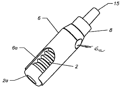
As shown in Fig. 1 the one way valve assembly 1 is composed of a
bellows container or source 2 holding a sterile flowable substance, a valve
assembly 3 for conveying the flowable substance from the container 2 to an
outlet when pressure is applied to the container 2 and an over cap 15 covering
the valve assembly 3 to prevent contamination from entering the valve
assembly 3 during storage.
The bellows container 2 collapses when pressure is applied to the
container, however, other containers may be used such as a tube or an internal
bag in a container which permit multi-dose dispensation of the flowable
substance without contamination entering the container following the
dispensing procedure.
The flowable substance may be a pharmaceutical, such as a eye care
solution, a food stuff, such as products or juices, and a cosmetic, such as a
skin
care solution or toiletries, and liquid vitamins, all of which are intended to
be
maintained free of contaminants from the ambient atmosphere.
The bellows container or source 2 is laterally enclosed by an axially
extending housing 6 to provide better ergonomic control during dispensing. A
7
CA 02628331 2008-05-02
WO 2007/055922 PCT/US2006/041840
slot 7 extending axially in the housing 6 permits a user to gain access to an
actuator 2a of the coniainer as the flowable substance is pressed out.
A collar 8 connects the valve body 3 to the container 2 affording a scaled
connection so that ambient contaminants cannot pass into the container 2.
The valve assembly 3 has an axially extending inner core 10 bearing
against the opening of the container 2 so that flow from the container enters
into
an axially extending blind passageway 11 in the inner core. The passageway 11
extends for a major portion of the axial length of the inner core. At
approximately half the length of the passageway 11 the inner core has at least
one port 12 extending transversely of the passageway axis from the surface of
the passageway to the outer surface of the inner core 10. The inner core 10 is
formed of a rigid plastic material and terminates inwardly of the outlet end
of
the valve body.
A flexible membrane 13, such as an elastomeric member, is fitted tightly
over the outer surface of the inner core and extends from the opening in the
container 2 to the opposite end of the inner core 10. As can be noted in Figs.
2a
and 2b, the thickness of the membrane is variable along its axial length and
in
the region of the outlet end of the inner core has an axially extending
8
CA 02628331 2008-05-02
WO 2007/055922 PCT/US2006/041840
continuous uninterrupted annular band considerably thicker than the remainder
of the flexible membrane 13, that is, the band is not separated in the axial
direction by axially extending cuts.
At its end adjacent the opening from the container, the flexible membrane
13 has an outwardly extending flange bearing against a fl.ange on the inner
core
is located at the opening from the container.
An axially extending valve cover 14 encircles the flexible membrane 13
and as shown in the rest position in Fig 2a is spaced radially outwardly from
the
outer surface of the flexible membrane. The end of the valve cover 14 adjacent
the container 2 has a radially outwardly extending flange 14a bearing against
the flange at the end of the flexible membrane effecting the seal for the
valve
body at the opening from the container 2.
The valve cover 14 is formed of an inner layer of an elastomeric material
extending axially from its flange 14a to and over the outlet end of the valve
body 3. The elastomeric material forms a soft cover 7 over the outlet end of
the
increased thickness which is particularly advantageous when the valve
assembly is used for dispensing an eye care solution. Such a soft cover 7
prevents any damage to the eye.
9
CA 02628331 2008-05-02
WO 2007/055922 PCT/US2006/041840
The soft cover 7 has an outlet orifice 7a for dispensing the flowable
substance. The outlet orifice is closed in the rest position of the one way
valve
assembly, however, when tize flowable substance is being dispensed and exits
the outlet end of the flexible membrane, it flows radially inward* to the
outlet
orifice which then opens allowing the substance to flow out of the valve
assembly. When the flowable substance is dispensed and pressure on the
source is withdrawn the outlet orifice 7a closes blocking any backflow into
the
valve assembly.
By selectively dimensioning the outlet orifice 7a a drop-like amount of
the flowable substance can be dispensed, for example if an eye care solution
is
being dispensed. If a greater amount of the flowable substance is to be
dispensed the outlet orifice 7a can be formed for dispensing a larger quantity
of
the flowable substance. The outer orifice 7a can be formed to provide a spray
or a stream of the flowable substance.
An over cap 15 is placed over the valve assembly when it is not in use
protecting it from contact with ambient contaminants and for unintended
dispensing.
CA 02628331 2008-05-02
WO 2007/055922 PCT/US2006/041840
When the flowable substance is to be dispensed, the over cap 15 is
removed and pressure is applied to the actuator 2a of the container so that an
amount of the flowable substance passes out of the container into the
passageway 11 in the inner core 10. The substance flows through the per-ts at
least one port 12 and expands the flexible membrane 13 radially outwardly and
flows toward the outlet end of the flexible membrane where it exits from the
flexible membrane radially inwardly into the outlet orifice 7a in the cover
and is
dispensed.
By releasing the pressure on the actuator 2a of the container, the
dispensing operation is terminated and the flexible membrane 13 returns
inwardly into contact with the outer surface of the inner core 10. The inward
movement of the flexible membrane start at its outlet end because of its
increased thickness and affords gradual contact with the outer surface of the
inner core returning any flowable substance through the ports back into the
container whereby contaminants cannot enter the container.
Dispensing individual portions of the flowable substance can be
continued until the container is almost completely emptied.
11
CA 02628331 2008-05-02
WO 2007/055922 PCT/US2006/041840
As mentioned, a variety of pharmaceuticals, cosmetics, food stuffs and
other flowable materials can be dispensed where it is important to maintain
them free of contaminants from the ambient atmosphere. The flowable
characteristics of the material being dispensed determines the type and
dimension of the valve body.
The material forming the outlet orifice 7a does not absorb the flowable
substance, any substance entering the outlet orifice is ejected and does not
return into the space between the inner core and the flexible membrane.
12