Note: Descriptions are shown in the official language in which they were submitted.
CA 02628480 2008-05-02
WO 2007/056397 PCT/US2006/043393
-1-
FLITCH PLANER
CROSS-REFERENCE TO RELATED APPLICATION
This application claims the benefit under 35 U.S.C. 119(e) of U.S.
provisional patent application Serial No. 60/734,943, filed 9 November 2005,
the
entirety of the disclosure of which is incorporated herein by reference.
FIELD OF THE INVENTION
This invention relates to planing and shaping equipment. It is
disclosed in the context of a planer for shaping flitches, longitudinal cuts
from the
trunks of trees. However, it is believed to be useful in other applications as
well.
BACKGROUND OF THE INVENTION
Various types of planers for shaping flitches are known. There are, for
example, the flitch planers illustrated and described in U. S. Patent
6,474,379, WO
03/070440, and U. S. published patent application 2005-0121106-Al, and
references
cited therein. No representation is intended by this listing that a thorough
search of all
material prior art has been conducted, or that no better art than that listed
is available.
Nor should any such representation be inferred. The disclosures of all of the
above
are hereby incorporated herein by reference.
DISCLOSURE OF THE INVENTION
According to an aspect of the invention, apparatus for shaping a flitch
includes a first shaping head assembly for shaping a first surface of the
flitch, a
second shaping head assembly for shaping a second surface of the flitch, and a
groover assembly for placing at least one groove in a surface of the flitch.
Further illustratively according to this aspect of the invention, the
apparatus includes a control system for providing a shaping solution and
controlling
the apparatus in accordance with the shaping solution to shape the flitch.
Further illustratively according to this aspect of the invention, the
apparatus includes a first frame assembly for supporting the'first shaping
head
assembly, the second shaping head assembly, and the groover assembly, and a
second
frame assembly. The first and second frame assemblies together comprise at
least one
CA 02628480 2008-05-02
WO 2007/056397 PCT/US2006/043393
-2-
slideway which extends in the directions of motion of the first frame
assembly, and at
least one bearing engaging the at least one slideway.
Illustratively according to this aspect of the invention, the at least one
bearing is provided on the first frame assembly.
Further illustratively according to this aspect of the invention, the
apparatus comprises a motor coupled between the second fraine assembly and the
first
frame assembly and actuable to shift the first frame assembly transversely of
the
direction of motion of the flitch through the apparatus.
Illustratively according to this aspect of the invention, the first shaping
head assembly is mounted to the first frame assembly by at least one slideway,
at least
one bearing slidable on the at least one slideway, and an actuator mounting
assembly
coupled between the first frame assembly and the first shaping head assembly
to
maintain the first shaping head assembly in a desired position to shape the
flitch.
Further illustratively according to this aspect of the invention, the
apparatus includes a press roll assembly mounted to the first shaping head
assembly
and a motor for maintaining a desired pressure on the flitch as the flitch
passes the
press roll assembly.
Illustratively according to this aspect of the invention, the second
shaping head assembly is mounted to the first frame assembly by at least one
slideway, at least one bearing slidable on the at least one slideway, and an
actuator
mounting assembly coupled between the first frame assembly and the second
shaping
head assembly to maintain the second shaping head assembly in a desired
position for
shaping the flitch.
Illustratively according to this aspect of the invention, the groover
assembly is mounted to the first frame assembly by at least one slideway, at
least one
bearing slidable on the at least one slideway, and an actuator mounting
assembly
coupled between the first frame assembly and the groover assembly to maintain
the
groover assembly in a desired position for placing at least one groove in a
surface of
the flitch.
Further illustratively according to this aspect of the invention, the
apparatus comprises a motor to control the first frame assembly and the
groover
assembly so that when the groover assembly is grooving a flitch, the first
frame
assembly moves transversely of the direction of motion of the flitch past the
groover
assembly.
CA 02628480 2008-05-02
WO 2007/056397 PCT/US2006/043393
-3-
Illustratively according to this aspect of the invention, the first shaping
head assembly is mounted to the first frame assembly by at least one slideway
and at
least one bearing. An actuator mounting assembly is coupled between the first
frame
assembly and the first shaping head assembly to maintain the first shaping
head
assembly in a desired position to shape the flitch.
According to another aspect of the invention, apparatus for conveying
a flitch includes at least one centering arm and chain runner assembly. The at
least
one centering arm and chain runner assembly includes a chain runner assembly
for
conveying the flitch toward a transverse center of the centering arm and chain
runner
assembly. The at least one centering arm and chain runner assembly further
includes
a centering arm assembly for positioning the flitch.
Further illustratively according to this aspect of the invention, the
apparatus includes at least one slide assembly, a slide frame for supporting
the slide
assembly, and a motor assembly for positioning at least a portion of the
centering arm
and chain runner assembly with respect to at least another portion of the
centering arm
and chain runner assembly.
Illustratively according to this aspect of the invention, the apparatus
includes first and second centering arm and chain runner assemblies. Each of
the first
and second centering arm and chain runner assemblies includes a chain runner
assembly for conveying the flitch toward a transverse center of the centering
arm and
chain runner assembly, a centering arm assembly for positioning the flitch, a
slide
assembly, a slide frame for supporting the slide assembly, and a lift motor
assembly.
Illustratively according to this aspect of the invention, a first one of the
slide frames is mounted on a slide base assembly for movement toward and away
from a second one of the slide frames.
Illustratively according to this aspect of the invention, the first one of
the slide frames is mounted on a slide base assembly.
Illustratively according to this aspect of the invention, one of the first
slide frame and the slide base includes at least one slideway and the other of
the first
slide frame and the slide base includes at least one bearing for engaging the
slideway
for movably mounting the first slide frame on the slide base.
Further illustratively according to this aspect of the invention, the
apparatus includes a chain runner assembly for moving the first one of the
slide
frames toward and away from the second one of the slide frames. The chain
runner
CA 02628480 2008-05-02
WO 2007/056397 PCT/US2006/043393
-4-
assembly includes an idler assembly mounted beyond a first limit of movement
of the
slide base and a drive assembly mounted beyond a second limit of movement of
the
slide base. I
Illustratively according to this aspect of the invention, the motor
assembly comprises a plurality of fluid cylinders. Actuation of a selected one
or
selected ones of the plurality of fluid cylinders permits at least a portion
of the
centering arm and chain runner assembly to be moved with respect to at least
another
portion of the centering arm and chain runner assembly a selected distance of
multiple
different distances.
Further illustratively according to this aspect of the invention, the
apparatus includes at least one slide assembly, a slide frame for supporting
the slide
assembly, a slideway mounted to one of the slide assembly and slide frame, and
at
least one bearing mounted to the other of the slide assembly and slide frame
to permit
relative movement between the slide assembly and slide frame.
Further illustratively according to this aspect of the invention, the
apparatus includes a motor assembly coupled between the slide frame and the
slide
assembly. Actuation of the motor assembly reciprocates the slide assembly with
respect to the slide frame.
Illustratively according to this aspect of the invention, the centering
arm and chain runner assembly includes a support, a drive sprocket, a driven
sprocket,
a drive motor, and a chain trained about the drive sprocket and driven
sprocket. The
chain is selectively driven by the drive motor to move the flitch along the
centering
arm and chain runner assembly.
Illustratively according to this aspect of the invention, the support
comprises a tubular support rotatably supporting the drive sprocket and the
driven
sprocket in spaced-apart orientation. The tubular support includes a wall
defining an
inside and an outside. The chain is trained about the sprockets with a first
bight of the
chain extending outside the wall and a second bight of the chain extending
inside the
wall.
Illustratively according to this aspect of the invention, the centering
arm and chain runner assembly comprises two centering arms. Each centering arm
includes gear teeth. A frame pivotally supports the centering arms with their
gear
teeth in engagement to synchronize their motion. A motor is provided for
moving the
centering arms between centering and releasing orientations.
CA 02628480 2008-05-02
WO 2007/056397 PCT/US2006/043393
-5-
Illustratively according to this aspect of the invention, the motor
comprises a piston-and-cylinder fluid motor.
According to another aspect of the invention, a flitch transport
conveyor includes a conveyor frame, a first dogger arm assembly for engaging a
first
end of the flitch and a second dogger arm assembly for engaging a second end
of the
flitch.
Illustratively according to this aspect of the invention, the conveyor
frame includes a first slideway and a second slideway. Each dogger arm
assembly
includes at least one bearing for engaging the first slideway, and a slide bar
for
engaging the second slideway.
Further illustratively according to this aspect of the invention, the
apparatus includes a first drive system for driving the first dogger arm
assembly along
the conveyor frame and a second drive system for driving the second dogger arm
assembly along the conveyor frame.
Illustratively according to this aspect of the invention, each of the first
and second drive systems includes a drive chain, a drive sprocket, an idler
sprocket,
and a drive motor. The drive chains are coupled to respective ones of the
first and
second dogger arm assemblies and extend about respective ones of the drive and
idler
sprockets.
According to another aspect of the invention, apparatus for shaping a
flitch includes a first shaping head assembly for shaping a first surface of
the flitch, a
second shaping head assembly for shaping a second surface of the flitch, and a
control
system for providing a shaping solution and controlling the apparatus in
accordance
with the shaping solution to shape the flitch.
Illustratively according to this aspect of the invention, the control
system includes a scanner for scanning the flitch before shaping the flitch.
The
control system provides the shaping solution to optimize the yield from the
flitch.
According to another aspect of the invention, apparatus for shaping a
flitch includes a first shaping head assembly for shaping a first surface of
the flitch, a
second shaping head assembly for shaping a second surface of the flitch, a
first frame
assembly for supporting the first and second shaping head assemblies, and a
second
frame assembly. The first and second frame assemblies together comprise at
least one
slideway which extends in the directions of motion of the first frame
assenzbly. The
apparatus further includes at least one bearing engaging the at least one
slideway.
CA 02628480 2008-05-02
WO 2007/056397 PCT/US2006/043393
-6-
Illustratively according to this aspect of the invention, the at least one
bearing is provided on the first frame assembly.
Further illustratively according to this aspect of the invention, the
apparatus comprises a motor coupled between the first and second frame
assemblies
and actuable to shift the first frame assembly transversely of the direction
of motion
of the flitch through the apparatus.
According to another aspect of the invention, apparatus for shaping a
flitch includes a shaping head assembly for shaping a surface of the flitch,
and a frame
assembly. The shaping head assembly is mounted to the frame assembly by at
least
one slideway. At least one bearing is slidable on the at least one slideway.
An
actuator mounting assembly is coupled between the frame assembly and the
shaping
head assembly to maintain the shaping head assembly in a desired position to
shape
the flitch.
Further illustratively according to this aspect of the invention, the
apparatus includes a press roll assembly mounted to the shaping head assembly
and a
motor for maintaining a desired pressure on the flitch as the flitch passes
the press roll
assembly.
According to another aspect of the invention, apparatus for shaping a
flitch includes a first shaping head assembly for shaping a first surface of
the flitch, a
second shaping head assembly for shaping a second surface of the flitch, and a
frame
assembly. The first shaping head assembly is mounted to the frame assembly by
at
least one slideway and at least one bearing. An actuator mounting assembly is
coupled between the frame assembly and the first shaping head assembly to
maintain
the first shaping head assembly in a desired position to shape the flitch.
According to another aspect of the invention, apparatus for shaping a
flitch includes a first shaping head assembly for shaping a first surface of
the flitch,
and a control system for providing a shaping solution and controlling the
apparatus in
accordance with the shaping solution to shape the flitch. A flitch transport
conveyor
includes a first dogger arm assembly for engaging a first end of the flitch
and a second
dogger arm assembly for engaging a second end of the flitch to convey the
flitch past
the first shaping head assembly.
Illustratively according to this aspect of the invention, the flitch
transport conveyor includes a conveyor frame. The conveyor frame includes a
first
slideway and a second slideway. Each dogger arm assembly includes at least one
CA 02628480 2008-05-02
WO 2007/056397 PCT/US2006/043393
-7-
bearing for engaging the first slideway and a slide bar for engaging the
second
slideway. First and second drive systeins drive the first and second dogger
arm
assemblies, respectively, along the conveyor frame.
Illustratively according to this aspect of the invention, each of the first
and second drive systems includes a drive chain, a drive sprocket, an idler
sprocket,
and a drive motor. The drive chains are coupled to respective ones of the
first and
second dogger arm assemblies and extend about respective ones of the drive and
idler
sprockets.
Illustratively according to this aspect of the invention, the apparatus
includes a second shaping head assembly for shaping a second surface of the
flitch.
Illustratively according to this aspect of the invention, the control
system includes a scanner for scanning the flitch before shaping the flitch.
The
control system provides the shaping solution to optimize the yield from the
flitch.
The flitch transport conveyor conveys the flitch first through the scanner to
provide a
shaping solution for the flitch and then past the first and second shaping
heads to
implement the shaping solution.
BRIEF DESCRIPTION OF THE DRAWINGS
The invention may best be understood by referring to the following
detailed description and accompanying drawings which illustrate the invention.
In the
drawings:
Figs. 1 a-c illustrate a top plan view of a system incorporating a flitch
planer constructed according to the invention;
Figs. 2a-d, respectively, illustrate a side elevational view (Fig. 2a) of a
scanner housing illustrated in Fig. lb, an end elevational view (Fig. 2b) of
the scanner
housing illustrated in Fig. 2a, taken from the downstream, or exit, end of the
scanner
housing, a top plan view (Fig. 2c) of the scanner housing illustrated in Figs.
lb, 2a
and 2b, and a side elevational view (Fig. 2d), viewed from the side opposite
the side
illustrated in Fig. 2a;
Fig. 3 illustrates a diagrammatic end elevational view of the scanner
housing illustrated in Figs. lb and 2a-d, with the sidewall removed to
illustrate
possible locations of scanners in the housing;
Figs. 4a-d illustrate an end elevational view, viewed from the
upstream, or entry, end (Figs. 4a-b), of the planing or shaping section
illustrated in
CA 02628480 2008-05-02
WO 2007/056397 PCT/US2006/043393
-8-
Fig. 1 b, a side elevational view, from the conveyor side (Fig. 4c), of the
planing or
shaping section illustrated in Figs. lb and 4a-b, and an end elevational view,
viewed
from the downstream, or exit, end (Fig. 4d), of the planing or shaping section
illustrated in Figs. lb and 4a-c;
Figs. 5a-f illustrate a side elevational view (Fig. 5a) of a lifting
conveyor section illustrated in Fig. 1 a, a top plan view (Fig. 5b) of the
lifting
conveyor section illustrated in Figs. 1a and 5a, a side elevational view of a
detail of
the lifting conveyor section illustrated in Figs. 1 a and 5a-b, a top plan
view (Fig. 5d)
of the detail illustrated in Fig. 5c, an end elevational view (Fig. 5e), from
the
downstream end of the conveyor, of the detail illustrated in Figs. 5c-d, and
an end
elevational view (Fig. 5f) of another detail of the lifting conveyor section
illustrated in
Figs. la and 5a-b;
Figs. 6a-b illustrate a top plan view (Fig. 6a) and an end elevational
view (Fig. 6b) of a detail of the conveyor illustrated in Figs. 1 a-c;
Figs. 7a-b illustrate a top plan view (Fig. 7a) and an end elevational
view (Fig. 7b) of a detail of the conveyor illustrated in Figs. 1 a-c; and,
Figs. 8a-d, 9a-c and l0a-e illustrate sequential function charts
(hereinafter sometimes SFCs) useful in understanding the invention.
DETAILED DESCRIPTIONS OF ILLUSTRATIVE EMBODIMENTS
Referring first to Figs. 1 a-c, a top plan view of a system incorporating
a flitch planer 202 according to the invention, a scanner section 200 includes
an
enclosure 204 (see also Figs. 2a-d) through which a flitch 206 to be planed,
or shaped,
passes for scanning by a number, illustratively, four, of scanners 210, for
example,
model DiSCAN 100 optical scanners available from Microtec S. r. I./GmbH,
Brixen,
Italy, as part of a DiSHAPE 100/4 3D shape scanner. See Fig. 3. The outputs of
the
scanners 210 are coupled by appropriate conductors (not shown) to a control
system
212 including, for example, an appropriately programmed personal computer
(hereinafter.sometimes PC), the program of which calculates an optimum shaping
strategy for the flitch 206 being scanned. A conveyor 220 extends through
enclosure
204 and conveys the flitch 206 through the enclosure 204 past the scanners
210,
where the flitch 206 is scanned and parameters obtained from the scanning are
output
to the control system 212. The control system 212 employs (an) algorithm(s) to
calculate a solution for the shape into which the flitch 206 is planed in alz
effort to
CA 02628480 2008-05-02
WO 2007/056397 PCT/US2006/043393
-9-
optimize the amount and quality of veneer which will subsequently be sliced
from the
thus-shaped flitch 206.
The flitch is then conveyed by conveyor 220 to a planing or shaping
section 222 (see also Figs. 4a-d) where the flitch 206 is planed in accordance
with the
solution provided by the control system 212. The planing section 222 is, of
course,
also coupled by appropriate conductors (not shown) to the control system 212
to
receive inputs therefrom to enable the planing section 222 to shape the flitch
206 in
such a way as to implement the solution. Referring specifically to Figs. 4b-d,
the
planing section 222 includes an upper flat planer head assembly 226, a lower
flat
planer head assembly 228, a press roll assembly 230, an upper concave planer
head
assembly 232, and a groover assembly 234 for placing one or more grooves in
the
back side of the flitch, for example, for the purposes illustrated and
described in U. S.
Patents 5,101,874 and 5,150,746.
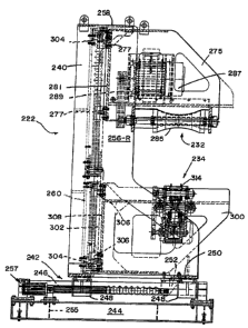
The planing section 222 includes an outer frame assembly 240 and a
slide base frame assembly 242 permitting movement of the outer frame assembly
240
transversely of the direction of motion of the flitch 206 on the conveyor 220
through
planing or shaping section 222. Slide base frame assembly 242 comprises a
rectangular I-beam base 244, a pair of cylindrical shafts 246 which extend in
the
directions of motion of the outer frame assembly 240, that is, transverse to
the
direction of motion of the flitch 206 through the planing section 222, and two
pairs of
linear bearings 248, each pair mounted on outer frame assembly 240 and
slidable on
one of the cylindrical shafts 246. The I-beam base 244 is constructed from,
for
example, 8" width, 40 lb./ft. I-beam. Shafts 246 illustratively are 5-1/2"
diameter
hard chromed steel shafts. The four linear bearings 248 are rectangularly
arrayed on
the underside of an outer frame bottom plate 250 of outer frame assembly 240.
Outer
frame bottom plate 250 illustratively is constructed from 1-1/2" thick steel
plate. A
rod eye mount 252 is provided on the underside of outer frame bottom plate
250.
Actuator trunnion mounts 254 are mounted on a cross member 255 of base 244. An
actuator 257, such as, for example, a Moog model 884-027 inline EMA, is
coupled
between rod eye mount 252 and trunnion mounts 254 and is actuable to shift
outer
frame assembly 240 transversely of the direction of motion of flitch 206
through
planing or shaping section 222.
Outer frame assembly 240 further includes outer frame left- and right-
hand sides 256-L and 256-R, respectively, an outer frame top plate 258 and an
outer
CA 02628480 2008-05-02
WO 2007/056397 PCT/US2006/043393
-10-
frame back plate 260. Outer frame back plate 260 and side plates 256-L and 256-
R
illustratively are constructed from 1" thick steel plate. Outer frame top
plate 258
illustratively is constructed from 3/4" thick steel plate.
Referring particularly to Figs. 4b-c, upper flat planer head assembly
226 is mounted to outer frame back plate 260 by a pair of vertically extending
roundways 269, 270 which are mounted by roundway support blocks 272 to outer
frame back plate 260. Upper flat planer head assembly 226 includes a weldinent
274
to the rear corners of which are mounted two pairs of linear bearings 276,
each pair
slidable on one of roundways 269, 270. The four linear bearings 276 are
rectangularly arrayed on the back side 280 of weldment 274. An actuator
mounting
assembly 282 is coupled between outer frame back plate 260 and back side 280
of
weldment 274 to maintain a rotatably mounted generally right circular
cylindrical
cutterhead 284 in a desired vertical position to implement the planing
solution.
Actuator mounting assembly 282 may again be a Moog model 884-027 inline EMA.
Cutterhead 284 is rotatably mounted in weldment 274 and is rotated by a motor
286,
such as, for example, a Toshiba CT, 40 hp, 575 V, 60 Hz, 3600 rpm, 324 TS
frame
motor, through a drive belt 288. Press roll assembly 230 is mounted to an
outer
sidewal1290 of weldment 274 and includes a pneumatic press roll cylinder
assembly
292 and a linear trunnion mount assembly 294 for maintaining a desired
pressure on
the top surface of flitch 206 as flitch 206 passes under press roll assembly
230.
Lower flat planer head assembly 228 and groover assembly 234 are
mounted in a lower support frame weldment 300. Lower support frame weldment
300 is mounted to outer frame back plate 260 by roundway 270 and a vertically
extending roundway 302 which is mounted by roundway support blocks 304 to
outer
frame back plate 260. Lower support frame weldment 300 includes two pairs of
linear bearings 306 rectangularly arrayed on the back side 308 of weldment
300. An
actuator mounting assembly 310 is coupled between outer frame back plate 260
and
back side 308 of weldment 300 to maintain a rotatably mounted generally riglit
circular cylindrical cutterhead 312 and a groover head 314 in desired vertical
positions. Actuator mounting assembly 310 may again be a Moog model 884-027
inline EMA. Cutterhead 312 is rotatably mounted in weldment 300 and is rotated
by
a motor 316, such as, for example, a Toshiba CT, 75 hp, 575 V, 60 Hz, 3600
rpm, 365
TS frame motor, through a drive belt 320. Groover head 314 and its drive motor
315
are pivotally mounted by a bearing and pillow block 317 from the underside of
the top
CA 02628480 2008-05-02
WO 2007/056397 PCT/US2006/043393
-11-
of weldment 300. A pneumatic cylinder 319 pivots groover head 314 upward into
grooving orientation with respect to any flitch 206 which requires a groove(s)
in its
underside. When the groover head 314 is grooving a flitch 206, actuator 257
may
also be actuated to move the groover head 314 transversely of the direction of
motion
of flitch 206 past groover head 314. This results in the groove(s) being cut
by groover
head 314 extending at a desired angle to the longitudinal extent of the flitch
206 being
grooved, so that when the flitch 206 is mounted to equipment for converting it
into
veneer, it is canted at an angle to horizontal, facilitating slicing of veneer
from the
flitch 206.
Referring particularly to Figs. 4c-d, upper concave planer head
assembly 232 is mounted to outer frame back plate 260 by vertically extending
roundway 302 and a vertically extending roundway 271 which is mounted by
roundway support blocks 273 to outer frame back plate 260. Upper concave
planer
head assembly 232 includes a weldment 275 to the rear corners of which are
mounted
two pairs of linear bearings 277, each pair slidable on a respective one of
roundways
271, 302. The four linear bearings 277 are rectangularly arrayed on the back
side 281
of weldment 275. An actuator mounting assembly 283 is coupled between outer
frame back plate 260 and back side 281 of weldment 275 to maintain a rotatably
mounted generally concave circular cylindrical cutterhead 285 in a desired
vertical
position to iinplement the planing solution. Concave planer head assembly 232
is
particularly useful in situations where flitches 206 are being prepared for
mounting on
staylogs to be cut during rotation of the staylogs. Actuator mounting assembly
283
may again be a Moog mode1884-027 inline EMA. Cutterhead 285 is rotatably
mounted in weldment 275 and is rotated by a motor 287, such as, for example, a
Toshiba CT, 40 hp, 575 V, 60 Hz, 3600 rpm, 324 TS frame motor, through a drive
belt 289.
Referring now specifically to Figs. 1a and 5a-f, conveyor 220 includes
a stationary centering arm and chain runner assembly 350 and a movable
centering
arm and chain runner assembly 352. Each of stationary centering arm and chain
runner assembly 350 and movable centering arm and chain runner assembly 352
includes a chain runner assembly 354 for conveying the flitch 206 toward the
transverse center of the assembly 350, a centering arm assembly 356 for
positioning
one of the ends of flitch 206, slide assemblies 358, a slide frame 360 for
supporting
slide assemblies 358, and a lift cylinder assembly 362. As best illustrated in
Figs. 5c,
CA 02628480 2008-05-02
WO 2007/056397 PCT/US2006/043393
-12-
e and f, each lift cylinder assembly 362 comprises three hydraulic cylinders
362a-c,
permitting its respective chain runner assembly 354 to be lifted to a selected
one of
three different heights by actuation of (a) selected one(s), or all, of the
three hydraulic
cylinders 3 62a-c, depending upon the amount of wood which is to be removed
from
the flitch 206, and whether wood is to be removed from the top side of the
flitch 206,
the bottom side of the flitch 206, or both.
Referring now particularly to Figs. 5c-f, each chain runner assembly
354 includes a rectangular cross section tubular chain race 363 supporting a
drive
sprocket 364 at one end and a driven sprocket 366 at the other end. The drive
sprocket 364 is driven by a chain drive 368 which illustratively is a Char-
Lynn 2000
series wheel motor, 29.8 c. i. d., model 105-1148. A chain 370 is trained
about the
sprockets 364, 366. The upper bight of the chain 370 extends across the
outside of the
top wall of the race 363. The lower bight of the chain 370 extends through the
interior of the race 363.
Centering arm assembly 356 includes a pair of centering arms 372 with
meshing gear teeth 374 to synchronize their motion, and a frame 376 for
pivotally
supporting the centering arms 372 with their gear teeth 374 in engagement.
Centering
arm assembly 356 also includes a motor 380, such as a Hydro-Line 2" bore by
10"
stroke hydraulic cylinder for moving centering arms 372 between their flitch
206-
centering and -releasing orientations.
Slide assemblies 358 each include a shaft 382, such as a 2" diameter
hard chromed steel shaft, mounted vertically to slide frame 360. A pair of
linear
bearings 384 is slidably mounted on each shaft 382. The linear bearings 384
are
mounted to franze 376, permitting centering arm assembly 356 to reciprocate
vertically with respect to slide frame 360.
Lift cylinder assembly 362 is coupled between slide frame 360 and
frame 376. Actuation of lift cylinder assembly 362 reciprocates frame 376, and
chain
runner assembly 354 and centering arm assembly 356 which are mounted to frame
376, vertically with respect to slide frame 360.
The slide frame 360-S of stationary centering arm and chain runner
assembly 350 is stationarily mounted, for example, on a veneer mill floor 386.
Referring specifically to Figs. 5a, b and f, the slide frame 360-M of movable
centering
arm and chain runner assembly 352 is mounted on a slide base assembly 390 for
movement toward and away from stationary centering arm and chain runner
assembly
CA 02628480 2008-05-02
WO 2007/056397 PCT/US2006/043393
- 13 -
350 to accommodate flitches 206 of different lengths. Slide base assembly 390
includes a pair of laterally spaced, longitudinally extending roundways 392,
such as,
for example, 3" diameter hard chromed steel shafts mounted on rails of the
slide base
390. Two pairs of slotted linear bearings 396 are mounted on the underside 398
of
slide frame 360-M. The laterally spaced pairs of slotted linear bearings 396
slidably
engage respective roundways 392 to permit movement of slide franle 360-M along
slide base assembly 390. A chain runner assembly 400 extends lengthwise of
slide
base assembly 390 between roundways 392. Chain runner assembly 400 includes an
idler assembly 402 mounted at one end of slide base 390, illustratively, the
end
thereof adjacent stationary centering arm and chain runner assembly 350. Chain
runner assembly 400 also includes a drive assembly 404 mounted at the other
end of
slide base 390. Drive assembly 404 includes a drive motor 406 and transmission
408,
illustratively a 5 h.p. vector motor and Cyclo model CHHM 6155YA51 reducer.
This
combination is capable of moving movable centering arm and chain runner
assembly
352 at about 60 ft./min. toward and away from stationary centering arm and
chain
runner assembly 350. A chain 410 is trained about idler and drive sprockets of
assemblies 402 and 404, and the ends of chain 410 are coupled to chain takeup
assemblies 412 provided on slide frame assembly 360-M.
Referring now specifically to Figs. 1 a-c, 4a-b, 6a-b and 7a-b, conveyor
220 further includes a flitch transport conveyor 420. Flitch transport
conveyor 420
includes a conveyor frame 422 fabricated from, for example, 6" wide, 20
lb./ft. I-
beam. Frame 422 illustratively extends about 88', a considerable portion of
the length
of the planer 202. Frame 422 includes an end dogger slide back channel 424,
and end
roundway 426 which illustratively is constructed from 3" diameter 4140/42
stock,
mounted on a rail. Flitch transport conveyor 420 further includes a pair of
dogger arm
assemblies 430, one, 430-L, for engaging the downstream end of the flitch 206,
and
one, 430-R, for engaging the upstream end of the flitch 206. It is here noted
that
dogger arm assemblies 430-L and 430-R are illustrated in two different
orientations in
Figs. la-c, but this is done for purposes of explanation only.
Each dogger arm assembly 430 includes a pair of slotted linear
bearings 432 on the underside thereof adjacent opposite sides of the dogger
arm
assembly 430 for engaging roundway 426, an end slide bar 434 at the rear end
of the
dogger arm assembly for engaging the end dogger slide back channe1424, and a
pivotally mounted spike plate 436 at the forward end of the dogger arm
assembly for
CA 02628480 2008-05-02
WO 2007/056397 PCT/US2006/043393
-14-
engaging an end of the flitch 206. Each dogger arm assembly 430 also includes
chain
takeup assemblies 438 adjacent opposite sides of the dogger arm assembly 430.
The
chain takeup assemblies 438 on dogger arm assembly 430-L are offset lengthwise
of
the dogger arm assembly (widthwise of the flitch transport conveyor 420) from
the
chain takeup assemblies 438 on dogger aim assembly 430-R, and each dogger arm
assembly 430-R, 430-L is shuttled along the length of flitch transport
conveyor 420
by a separate drive chain 440-R, 440-L, respectively. This permits the dogger
arm
assemblies 430-R, 430-L to be separately brought into engagement with the
respective
opposite ends of flitch 206 without regard to the length of the flitch 206.
The two
chains 440-R, 440-L run side by side, and a chain runner bar 442 is provided
on the
top side of each dogger arm assembly 430-R, 430-L to accommodate the drive
chain
440-L, 440-R of the other dogger arm assembly 430-L, 430-R, respectively.
Drive
chains 440-L, 440-R are trained about idler sprockets 444-L, 444-R,
respectively, at
the upstream end of flitch transport conveyor 420, and about drive sprockets
446-L,
446-R, respectively, at the downstream end of flitch transport conveyor 420.
Drive
sprockets 446-L, 446-R are coupled through suitable transmissions to the
output
shafts of flitch transport conveyor 420 drive motors 448-L, 448-R,
respectively.
Drive motors 448 illustratively are 60 h. p. 575 V, vector drive, 60 Hz, 3600
r. p. m.
364 TC frame motors.
Turning now to Figs. 8a-d, an infeed routine is initialized in a step
1000. At this time, the infeed is clear and the flitch 206 is resting against
a set of
pivotally deployable stops 462 near the top of entry end conveyor 460. A
scanner 458
arrayed across entry end conveyor 460 provides data related to the length of
the flitch
206, and the control system 212 uses this data to position the movable
centering arm
and chain runner assembly 352 for infeed of the flitch 206 in a step 1014.
After this
step, the movable centering arm and chain runner assembly 352 is in position.
The
control system 212 then waits for the return of the dogs 430 to the upstream
end of the
conveyor 220 in a step 1015. At this time, the stationary centering arm and
chain
runner assembly 350 and the movable centering arm and chain runner assembly
352
are ready to position, lift and center the flitch 206. The stationary
centering arm and
chain runner assembly 350 and the movable centering arm and chain runner
assembly
352 are in position to center the flitch 206 and raise the flitch 206 into
position to be
dogged by dogs 430 in a step 2001. The control system 212 requests the flitch
206
from the top of entry end conveyor 460 in a step 2002. At this time, the
stationary
CA 02628480 2008-05-02
WO 2007/056397 PCT/US2006/043393
-15-
centering arm and chain runner assembly 350 and the movable centering arm and
chain runner assembly 352 receive flitch 206 from the top of entry end
conveyor 460.
The chains 370 of stationary centering arm and chain runner assembly
350 and the movable centering arm and chain runner assembly 352 are run to
center
the flitch 206 on the stationary centering arm and chain runner assembly 350
and the
movable centering arm and chain runner assembly 352 in a step 2016 and a step
3003,
Fig. 8b. At this time, the flitch 206 is clear of the top of entry end
conveyor 460. The
flitch 206 continues to move forward in a step 2017, Fig. 8c, and a step 3004.
At this
time, the flitch 206 is on the entry ends of the chains 370. The chains 370
continue
moving flitch 206 forward in a step 2018 and a step 3005. The chains 370 are
stopped
in a step 2019 and a step 3006.
The centering arms 372 are actuated to center flitch 206 in a step 3007,
Fig. 8c. The hydraulic cylinders 362a-c are actuated to raise or lower flitch
206 as
necessary in a step 3008. The control system 212 then requests the centering
arms
372 to release the flitch 206 and flitch 206 to be dogged in a step 3009. The
centering
arms 372 release flitch 206 in a step 3010. The centering arms 372 are lowered
in a
step 3011, Fig. 8d. The dogs 430 are then clear to transport flitch 206 in a
step 3012.
The infeed lift and center routine completed, the routine is reset in a step
3013.
Turning now to Figs. 9a-d, a dog and release flitch routine waits for
dogging to be initiated in step 4000. Both dog 430-R, 430-L axes (each dog 430
is an
independerit axis of motion having its own motion controller and motor 448)
are
turned off in a step 4001. Dog 430-R, 430-L starting positions are saved in
order to
limit the distance through which the dogs 430-R, 430-L have to be moved to
engage a
flitch 2,06 in a step 4008. In a step 401,0, the routine assumes the dogs 430-
R, 430-L
are moved if current dog 430-R, 430-L positions are reached. The routine waits
for
the dogs 430-R, 430-L to stop moving and assumes that the dogs 430-R, 430-L
are in
contact with the flitch 206 in a step 4019. Full dogging torque is applied by
the dog
drive motors 448-L, 448-R in a step 5002.
Holding torque is applied by the dog drive motors 448-L, 448-R in a
step 5003, Fig. 9b. Two different methods were explored for holding the flitch
206.
In a so-called "torque mode," a constant torque was applied by one of the dog
drive
motors 448-L, 448-R and position controlled the other. In a so-called "gear
mode,"
the two dog drive motors 448-L, 448-R were electronically geared together as a
master and a slave. It was determined that the gear mode worked more reliably
to
CA 02628480 2008-05-02
WO 2007/056397 PCT/US2006/043393
-16-
hold the flitch 206, as a result of which the gear mode was implemented in the
control
system 212 in its current state. One dog 430-R, 430-L drive motor 448-L, 448-R
is
turned on in torque mode and both motor 448-L, 448-R axes are turned on in
gear
mode in a step 5012. The drive motors 448-L, 448-R are turned on if the dogs
430-R,
430-L are in gear mode in a step 5021. The dog 430-R, 430-L separation
distance is
saved in a step 6004. Simultaneously with steps 4010-6004, the routine watches
for
problems in the dogging operation in a step 4014, Fig. 9a, and watches for
maximum
dog 430-R, 430-L travel to be exceeded in a step 5011.
The flitch 206 is dogged and holding is continued in a step 6009, Fig.
9b. The routine checks to be sure the dogs 430-R, 430-L are not moving with
respect
to each other in a step 6017, Fig. 9c. One of the dog 430-R, 430-L drive
motors 448-
L, 448-R is turned on if the dogs 430-R, 430-L are in torque mode in a step
7005.
Simultaneously with steps 6009-7005, the routine watches for the dogs 430-R,
430-L
to get too close in a step 6013, Fig. 9b, and remembers if a fault occurred in
a step
6015, Fig. 9c. The dogs 430-R, 430-L are moved a set distance from the flitch
206 to
release the flitch in a step 7018. The routine is reset in a step 8007.
Turning now to Figs. 1 a-e, a routine for planing flitches 206 begins
with initialization of the routine, step 9000, Fig. 10a. If the routine is not
in the
AUTO mode, step 9100, the routine issues a STOP DRIVES 448-L, 448-R command,
step 9102, the routine is reset, step 9318, Fig. 10c, and returns to the
initialization step
9000, Fig. 10a.
If the routine is in the AUTO mode, step 9200, no flitch 206 is dogged,
the conveyor 420 outfeed is clear and the GO switch on control system 212 is
activated, step 9300, both dog drives 448-L, 448-R are enabled in servo mode,
step
9302. The dogs 430-R, 430-L are moved to LOAD positions, step 9304. The dogs
430-R, 430-L are then in position for a flitch 206 to move to the conveyor 420
infeed,
step 9306, Fig. lOb. A flitch 206 is loaded on the conveyor 420 infeed, step
9308.
The dogs 430-R, 430-L are moved to pre-dogging positions, step 9310. The dogs
430-R, 430-L are in the pre-dogging positions and the POSITION VERIFY switch
on
control systein 212 has been activated, step 9312. The DOG FLITCH 206 command
is then issued, step 9314, Fig. l Oc, and the routine receives the DOG FLITCH
206
command, step 9316. The routine is reset, step 9318, and returns to the
initialization
step 9000, Fig. 10a.
CA 02628480 2008-05-02
WO 2007/056397 PCT/US2006/043393
-17-
If the routine is in the AUTO mode, step 9200, a flitch 206 has been
dogged and the GO switch on control system 212 is activated, step 9400, Fig.
10a,
and a flitch 206 is at the conveyor 420 infeed zone, step 9402, the flitch 206
is moved
to the scanner 200 outfeed zone, step 9404, being scanned for a planing
solution as it
proceeds to the scanner 200 outfeed zone. If the flitch 206 is in position at
the
scanner 200 outfeed zone, step 9406, the routine determines if the planer
heads 226,
228, 230, 232, 234 are on and in position and the GO switch on control system
212 is
activated, step 9408. The flitch 206 is moved to the planer 222 outfeed, being
planed
as it proceeds through the planer 222, step 9410. Once the flitch 206 is in
position at
the planer 222 outfeed, step 9412, Fig. l Oc, the flitch 206 is released at
the planer 222
outfeed, step 9414. The routine waits until the flitch 206 is clear of the
planer 222
outfeed, step 9416, and is reset, step 9318 and returns to the initialization
step 9000,
Fig. 10a.
As an alternative to steps 9402, 9404 and 9406, the flitch 206 may
already be at the scanner 200 outfeed zone, step 9500, Fig. 10a. In this case,
the
routine proceeds through steps 9408, 9410, 9412, 9414, 9416 and 9318, Figs.
lOb-c,
as described above.
As an alternative to steps 9402, 9404, 9406, 9408, 9410 and 9412 or
9500, 9408, 9410 and 9412, in step 9600, Fig. lOd, the flitch 206 is at the
outfeed
zone. The routine then proceeds through steps 9414, 9416 and 9318, Fig. 10c,
as
described above.
As another altemative to steps 9402, 9404, 9406, 9408, 9410 and 9412
or 9500, 9408, 9410 and 9412, in step 9700, Fig. l Od, second pass (through
the planer
222) data is present and the flitch 206 is beginning a second pass through the
planer
222. The flitch 206 is moved to the outfeed. The dogs 430-R, 430-L are moved
to
the planer 222 outfeed, step 9702. A second planer 222 pass software word in
the
routine is cleared, step 9704. The routine then proceeds through steps 9414,
9416 and
9318, Fig. l Oc, as described above.
As an alternative to step 9700, Fig. 10d, second pass data is present
and the flitch 206 is not yet at the planer 222 infeed, step 9800. The dogs
430-R, 430-
L are moved to the scanner 200 outfeed, step 9802, and the second pass data is
sent to
the planer heads 226, 228, 230, 232, 234, step 9804. The routine then proceeds
through steps 9702, 9704, 9414, 9416 and 9318, Figs. 10d and c, as described
above.
CA 02628480 2008-05-02
WO 2007/056397 PCT/US2006/043393
-18-
As an alternative to step 9800, Fig. l Od, second pass data is present
and the planer 222 is open, step 9900. The routine then proceeds through steps
9802,
9804, 9702, 9704, 9414, 9416 and 9318, Figs. lOd and c, as described above.
As another alternative to steps 9402, 9404, 9406, 9408, 9410 and 9412,
in a step 10000, Fig. 10e, third pass (through the planer 222) data is present
and the
flitch 206 is beginning a third pass through the planer 222. The dogs are sent
to the
planer 222 outfeed- for the third pass, step 10002. A third planer 222 pass
software
word in the routine is cleared, step 10004. The routine then proceeds through
steps
9414, 9416 and 9318, Fig. l Oc, as described above.
As an alternative to step 10000, third pass data is present and the flitch
206 has not yet reached the planer 222 infeed, step 10100, Fig. 10e. The dogs
are
moved to the scanner 200 outfeed, step 10102. The third pass data is then sent
to the
planer heads 226, 228, 230, 232, 234, step 10104. The routine then proceeds
through
steps 10002, 10004, 9414, 9416 and 9318, Figs. l0e and c, as described above.
As an alternative to step 10100, third pass data is present and the
planer 222 is opened (that is, all of heads 226, 228, 230, 232, 234 are
withdrawn),
step 10200, Fig. 10e. The routine then proceeds through steps 10102, 10104,
10002,
10004, 9414, 9416 and 9318, Figs. 10e and c, as described above.