Note: Descriptions are shown in the official language in which they were submitted.
CA 02628524 2008-04-07
HBA055EP
1
SOUND TUNING METHOD
FIELD OF TECHNOLOGY
The invention relates to a sound tuning method, and in par-
ticular to a method for the automated sound tuning or equal-
izing in passenger spaces of motor vehicles.
BACKGROUND
In motor vehicles, particularly in premium class limousines,
the sound systems are typically very complex and comprise a
multiplicity of loudspeakers at the most varied positions in
the passenger space of such vehicles, using loudspeakers and
groups of loudspeakers for different frequency ranges (for
example subwoofers, woofers, mid-frequency loudspeakers and
tweeters, etc.). Such sound systems are manually adjusted or
optimized by acousticians or sound engineers for the respec-
tive vehicle type in order to achieve a desired sound im-
pression. This process is also called sound tuning which is
mainly tuning of the sound system and is subjectively per-
formed by the acousticians or sound engineers mainly on the
basis of experimental values and on the basis of the trained
hearing. Typical arrangements for signal processing used in
connection with sound tuning are biquadratic filters (e.g.,
high-pass, band-pass, low-pass, all-pass filters), bilinear
filters, digital delay lines, cross-over filters and ar-
rangements for changing the dynamic range of the signal
(e.g., compressors, limiters, expanders, noise gates etc.)
wherein the relevant parameters of the cut-off frequencies
of the cross-over filters, of the delay lines and of the am-
plitude response are adjusted in such a manner that a sound
impression is achieved which is optimized with regard to its
CA 02628524 2013-01-30
HBA055EP
2
spectral balance (tonality) and auditory perspective.
The focus of such tuning is to achieve as good as possible a
sound impression at all listening positions, i.e, all seat
positions in the passenger space of a passenger car. Howev-
er, a multiplicity of parameters has to be changed in this
process which cannot be adjusted independently of one anoth-
er and interact in their effect so that the procedure re-
suits in an iterative process which requires a high degree
of experience, is correspondingly time-consuming and inevi-
tably orientates itself largely around the subjective sound
impression of the acoustician or sound engineer performing
the tuning of the sound system. Therefore, it is a general
need to provide a method which provides for at least par-
tially automated tuning of sound systems in motor vehicles.
SUMMARY
According to one embodiment of the invention a method for
automated tuning of a sound system having delay lines,
equalizing filters, and at least two loudspeakers comprises
the steps of: reproducing a useful sound signal through the
loudspeakers, measuring sound pressure values at at least
one location, providing a target transfer function for tun-
ing the delay lines and the equalizing filters of the sound
system, the target transfer function representing a desired
transfer characteristics of the sound system, adjusting the
delay of the delay lines, and adjusting amplitude responses
of the equalizing filters such that the actual transfer
characteristics of the sound system approximates the target
function.
According to another embodiment of the invention a system
for automated tuning of a sound system comprises a signal
CA 02628524 2013-01-30
HBA055EP
3
source for providing a useful sound signal, a plurality of
adaptive filters, wherein one adapted filter is connected
downstream of each cross-over filter, a plurality of loud-
speakers, wherein one loudspeaker is connected downstream of
each adaptive filter, a microphone for measuring a sound
pressure level located at a first position and providing a
microphone signal representing the useful sound signal, a
control unit for optimising filter coefficients of the adap-
tive filters such that the actual transfer characteristics
defined by the useful sound signal and the microphone signal
approximates a target function which represents a desired
transfer characteristics of the sound system.
BRIEF DESCRIPTION OF THE DRAWINGS
The present invention can be better understood with refer-
ence to the following drawings and the description. The com-
ponents in the figures are not necessarily to scale, empha-
sis instead being placed upon illustrating the principles of
the invention. Moreover, in the figures, like reference nu-
merals designate corresponding parts throughout the differ-
ent views.
Figure 1 shows three-dimensional views of an energy decay
curve of the impulse responses of the sound system
according to the linear-, delay-, filter-, and
tuning-set;
Figure 2 illustrates three-dimensional energy decay curves
of the impulse responses of the linear-, delay-,
filter-, and tuning-set;
Figure 3 is a three-dimensional view and the top view of
the energy decay curve of the impulse response
CA 02628524 2008-04-07
HBA055EP
4
when tuning the delay lines without at the same
time tuning the cross-over filters,
Figure 4 is a diagram illustrating the masking thresholds
of white noise over frequency;
Figure 5 is a diagram illustrating the masking thresholds
depending on the sound pressure level of narrow-
band noise;
Figure 6 is diagram illustrating the masking thresholds
with critical-band-wide narrow-band noise;
Figure 7 is diagram illustrating the masking thresholds of
sinusoidal tones;
Figure 8 is a diagram of simultaneous, pre- and post-
masking;
Figure 9 is a diagram illustrating the dependence of the
loudness perception on the duration of a test tone
pulse;
Figure 10 is a diagram illustrating the dependence of the
masking threshold on the repetition rate of a test
tone pulse;
Figure 11 is a diagram illustrating post-masking;
Figure 12 is a diagram illustrating post-masking in depend-
ence on the duration of the masker;
Figure 13 is a diagram illustrating simultaneous masking by
a complex tone;
CA 02628524 2013-01-30
HBA055EP
Figure 14 illustrates the behaviour of sinusoidal pulses
transmitted by a sound system;
5 Figure 15 shows spectrograms of sinusoidal pulses according
to the linear-, delay-, filter-, and tuning-set;
Figure 16 shows graphs illustrating the transfer functions
determined from a number of sinusoidal pulses each
according to the linear-, delay-, filter- and tun-
ing-set;
Figure 17 is a graph illustrating the masking thresholds of
white noise and filtered white noise;
Figure 18 is a graph illustrating the frequency response of
a sound system in comparison with the frequency
response determined with the so-called Johnston
method;
Figure 19 is a graph illustrating equalizing according to
the Johnston method based on the difference of two
masking thresholds determined with filtered and
unfiltered white noise;
Figure 20 is a block diagram showing the basic structure of
an adaptive filter;
Figure 21 is a block diagram of an arrangement for automatic
adjustment of the delay time (phase) or equaliza-
tion having an adaptive system;
Figure 22 is a diagram showing the basic structure of an ar-
rangement for obtaining a target function as basis
for tuning the delay time (phase);
CA 02628524 2013-01-30
HBA055EP
6
Figure 23 is a time/frequency representation of the target
function for tuning the delay time (phase) or
equalization;
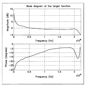
Figure 24 is a bode diagram of the target function for tun-
ing the delay time (phase) or equalization;
Figure 25 is a diagram illustrating the target frequency re-
sponse for pink noise;
Figure 26 is a block diagram illustrating a system for ob-
taining a target function for the tuning of delay
lines and filters;
Figure 27 is a time/frequency representation of the common
target function for the tuning of delay lines and
filters; and
Figure 28 is a bode diagram of the target function for joint
tuning of delay lines and filters.
DETAILED DESCRIPTION
In the present case, investigations have been conducted in
order to determine first how acoustic parameters are changed
when tuning is performed by trained acousticians or sound
engineers. As a test environment, a premium class limousine
has been selected. The sound system of this vehicle compris-
es a total of 10 channels (FrontLeft (LF), FrontRight (FR),
Centre (C), SideLeft (SL), SideRight (SR), RearLeft (RL),
RearRight (RR), SubwooferLeft (SubL), SubwooferRight (SubR),
a separate subwoofer (Sub) located in the trunk and an am-
plifier for each channel. The tuning is performed using both
phase tuning by changing the parameters of delay lines, all-
pass filters and cross-over filters, and frequency tun-
CA 02628524 2008-04-07
HBA055EP
7
ing by changing the parameters of biquadratic, bilinear fil-
ters and cross-over filters. The separate subwoofer placed
in the trunk of the vehicle is an active loudspeaker oper-
ated with a low-pass filter having a 100 Hz cut-off fre-
quency, 900 phase shift, and volume set to the centre posi-
tion.
The sound impression of the sound system of the vehicle is
tuned as it is conventionally done when tuning sound systems
in motor vehicles, in accordance with conventional manual
procedure by acousticians with emphasized optimization for
the two front seat positions (driver and co-driver), the
main attention here in turn being paid to the driver posi-
tion in accordance with the typical procedure. Also in ac-
cordance with the typical procedure, the rear seat positions
are also taken into consideration during the tuning process,
but only to an extent which does not result in any negative
impairment of the hearing impression on the front seat posi-
tions. During the tuning, a surround-algorithm (e. g.
Logic7) available in the sound system used is switched off
and only tuning for the case of pure stereo signals is per-
formed.
After completion of the manual tuning, measurements of the
impulse response of the total system are performed at four
positions in the passenger space (front left (driver), front
right (co-driver), rear left and rear right). During this
process, the total impulse response was determined in four
steps, firstly of the untuned sound system, of the com-
pletely tuned sound system, of the sound system tuned only
with regard to phase (delay lines) and of the sound system
tuned only with regard to the level variation or amplitude
response, respectively. These overall impulse responses are
then subjected to an analysis.
CA 02628524 2013-01-30
HBA055EP
8
There is a multiplicity of possibilities for analysing the
measured impulse responses. Thus, for example, the complete
impulse responses present in the time domain can be compared
with one another or these can be subjected in advance to
suitable filterings and then compared with one another in
the time domain. Furthermore, the measured impulse responses
can be transformed into the frequency domain in order to ex-
tract and to compare the static frequency response (ampli-
tude and phase response) or the associated static group-
delay response.
A further possibility consists in investigating the dynamic
characteristics of the impulse response and to evaluate the-
se, for example, by means of the energy decay curve, the
phase decay curve or also the group-delay decay curve. A
further possibility is to concentrate only on the minimum-
phase component (the component without time offset) of the
impulse response during the investigations or to consider
only the all-pass-containing component of the impulse re-
sponse (the component with frequency-dependent phase shift).
The examples mentioned only represent a section from the
possible range of investigation variants.
Initially, it had been a further focus of the investigation
to select the analysis method which represents the basis for
the best results of the evaluation and analysis of the im-
pulse responses. After using and checking a multiplicity of
different analyses of the impulse responses measured, the
energy decay curve has then been selected as analysis meth-
od.
Further, the impulse responses are additionally investigated
for their dynamic characteristics with single sinusoidal
pulses being used as excitation signals for the sound sys-
CA 02628524 2013-01-30
HBA055EP
9
tern, their frequency being increased step by step in accord-
ance with the psychoacoustic Bark scale. In this method (the
so-called Liberatore method), the psychoacoustic character-
istics of the human ear are utilized, particularly the fre-
quency-dependent integrating characteristic of the human
ear. In this context, the starting point for modelling the
psychoacoustic hearing sensations are the fundamental char-
acteristics of the human ear, particularly of the inner ear.
The human inner ear is embedded in the so-called "temporal
bone" and filled with incompressible lymphatic fluid. The
inner ear has the shape of a snail (cochlea) with approxi-
mately 2.5 turns. The cochlea, in turn, consists of parallel
canals, the upper and lower canal being separated by the
basilar membrane. On this membrane, the organ of Corti is
located with the sensual cells of the ear. If the basilar
membrane is made to vibrate due to sound stimuli, so-called
travelling waves are formed, that is to say there are no
nodes or antinodes. In this way, an effect which is deter-
mined for the hearing process is produced, the so-called
frequency/locus transformation on the basilar membrane which
explains, amongst other things, psychoacoustic masking ef-
fects and the distinct frequency selectivity of the ear.
The human ear combines various sound stimuli falling within
limited frequency bands (integrating function). These fre-
quency bands are called critical bands or also critical
bandwidth CB. The critical bandwidth has its basis in that,
the human ear combines sounds which occur in particular fre-
quency bands with regard to psychoacoustic hearing sensa-
tions produced by these sounds to form a joint hearing sen-
sation. Sound events located within a critical band influ-
ence each other differently from sounds which occur in dif-
ferent critical bands. For example, two tones having the
same level within one critical band are perceived more qui-
CA 02628524 2013-01-30
HBA055EP
etly than when they are located in different critical bands.
Since a test tone within a masker can be heard when the en-
5 ergies are identical and the masker falls into the frequency
band which has the frequency of the test tone as centre fre-
quency, the required bandwidth of the critical bands can be
determined. At low frequencies, the critical bands have a
bandwidth of 100 Hz. At frequencies above 500 Hz, the criti-
10 cal bands have a bandwidth which is about 20% of the centre
frequency of the respective critical band (Zwicker, E.;
Fastl, H. Psychoacoustics - Facts and Models, 2nd Edition,
Springer-Verlag, Berlin/Heidelberg/New York, 1999).
By lining up all the critical bands over the entire hearing
range, a hearing-oriented non-linear frequency scale is ob-
tained which is called critical-band rate scale (tonality)
which has the unit Bark. It represents a distorted scaling
of the frequency axis such that critical bands are the same
width of exactly 1 Bark at any point. The nonlinear rela-
tionship of frequency and critical-band rate scale has its
origin in the frequency/locus transformation on the basilar
membrane. The critical-band rate scale function was speci-
fied by Zwicker in table form (Zwicker, E.; Fastl, H. Psy-
choacoustics - Facts and Models, 2nd Edition, Springer Ver-
lag, Berlin/Heidelberg/New York, 1999) on the basis of mask-
ing threshold and loudness investigations. It is found that
just 24 critical bands can be lined up in the auditory fre-
quency band from 0 to 16 kHz so that the associated critical
band-rate scale is 0 to 24 Bark.
For the application of the above-mentioned Liberatore
method, this means that excitation of the sound system by
sinusoidal pulses begins at about 20 Hz and is correspond-
ingly increased followed by a pause in each case. Following
CA 02628524 2013-01-30
HBA055EP
11
this, the sinusoidal pulses are convoluted with the respec-
tive impulse response to be analysed as a result of which a
result similar to the energy decay curve is again achieved
which allows a further penetrating analysis of the behaviour
of the sound system in the passenger space of the motor ve-
hicle.
The results achieved with the aid of the energy decay curves
described above are first shown, namely for the overall im-
pulse responses, measured in four steps, of the untuned
sound system, of the completely tuned sound system, of the
sound system only tuned with regard to phase (delay lines,
cross-over filters) and of the sound system, only tuned
manually by acousticians or sound engineers with regard to
the level variation or amplitude response, respectively (bi-
quadratic filters, bilinear filters) of the limousine under
investigation. These energy decay curves are represented in
a three-dimensional view in Figure 1.
The curves shown in Figure 1 are only within a frequency
range of up to f = 2 kHz since this represents the determin-
ing part-area of the audio frequency range with regard to
the sound sensations of auditory perspective and tonality to
be investigated. The extent of the three-dimensional repre-
sentations with time is restricted to about t - 280 ms since
it can be assumed that after this time, any signal of the
sound system excited by a pulse has decayed in the interior
space of the vehicle to the extent that the impulse response
provides no further contribution with regard to the sound
sensations of auditory perspective and tonality to be inves-
tigated.
Figures 1A-1D comprise four three-dimensional representa-
tions of the energy decay curves (EDC) determined. In all
CA 02628524 2013-01-30
HBA055EP
12
four representations, the Y axis designates the time in ms
after the corresponding sinusoidal pulse has been presented,
the X axis designates the level measured in each case at
this time and the Z axis designates the frequency of the re-
spective sinusoidal pulse, the frequency being plotted along
the Z axis from high frequencies towards low frequencies in
these representations. Furthermore, areas marked with H rep-
resent high measured levels and areas marked with L show low
measured levels. The transition from high levels (H) to low
levels (L) is identified by Ti and 12. The representation in
Figure lA shows the energy decay curve for the sound system
of the vehicle which is initially not tuned, also called
linear set in the following. The representation in Figure 1B
shows the energy decay curve for the sound system of the ve-
hicle tuned with regard to phase (delay lines, cross-over
filters), the adjustments used also being called delay set
in the following. The representation in Figure 10 shows the
energy decay curve for the sound system of the vehicle tuned
additionally with regard to the level variation or the am-
plitude response, respectively, (biquadratic filters, bilin-
ear filters) in a further step, the adjustments used also
being called filter set in the following. The representation
in Figure 1D finally shows the energy decay curve for the
sound system of the vehicle completely tuned in the itera-
tive method described above, this iterative process compris-
ing alternating retuning both of the biquadratic and biline-
ar filters and of the delay lines and of the cross-over fil-
ters in order to reach the final adjustment of the sound
system. The adjustments used during this process are also
called tuning-set in the following.
From the energy decay curve of the impulse response in the
interior vehicle space for the sound system initially not
CA 02628524 2013-01-30
HBA055EP
13
tuned, it can be seen from Figure 1A, that the direct sound
exhibits strong fluctuations and the reverberation is long
and energy-rich in many frequency bands. The tuning of the
sound system usually begins with tuning the cross-over fil-
ters and the delay lines. According to experience, this rep-
resents the most lengthy and difficult work in the tuning of
a sound system. After the cross-over filters and the delay
lines have been adjusted for adjusting the phase of the
sound system in the vehicle, an impulse response is measured
in the present case, the energy decay curve of which is
shown at the top right (delay set). It can be clearly seen
that a delay tuning (adjustment of the phase) performed man-
ually by experienced acousticians primarily minimizes the
reverberation in order to approach the desired sound impres-
sions for auditory perspective and tonality.
Figure 10 is the energy decay curve of the sound system for
the case where the equalizer filters (the biquadratic and
bilinear filters) were manually tuned (filter set) in addi-
tion to the cross-over filters and delay lines in a further
non-iterative step. It can be seen that good equalizing of
the amplitude response results in the reduction of individu-
al spatial modes occurring increasingly due to resonances of
the room acoustics of the vehicle space, and a certain
smoothing of the direct sound which thus essentially im-
proves the tonality.
Figure 1D shows the energy decay curve of the completely
tuned vehicle (tuning set). In this case, the iterative pro-
cedure described above was now used in the tuning of the
components of the sound system, that is to say especially
CA 02628524 2013-01-30
HBA055EP
14
the repetitive alternate tuning both of the biquadratic and
bilinear filters and of the delay lines and of the cross-
over filters in order to achieve the final adjustment of the
sound system with regard to the desired sound effect with
respect to auditory perspective and tonality. In this con-
text, from the representation in Figure 1 at the bottom
right it can be seen that the adjustments made now lead to a
type of compromise between the results of the phase tuning
and of the amplitude tuning. On the one hand, the reverbera-
tion is no longer suppressed as much as in pure delay tuning
(phase) and, on the other hand, some spatial modes are again
emphasized a little more than was the case in pure filter
tuning (amplitude response).
To illustrate the relationships, the top view of the three-
dimensional impulse responses of the sound system is chosen
in Figures 2A-2D as additional types of representation since
further features of the tuning of the sound system can be
seen better from this type of representation. The X axis
designates the frequency of the sinusoidal pulses in Hz in
all representations according to Figures 2A-2D, the y axis
designates the time after the end of the presentation of the
sinusoidal pulse. Furthermore, areas marked H again repre-
sent high measured levels and areas shown in L represent low
measured levels. The transition from high levels (H) to low
levels (L) is identified by Ti and T2. Figures 2A-2D again
comprise the representation of the energy decay curves of
the measured impulse responses of the sound system used in
the investigations for the cases of the untuned sound system
(linear set, top left), of the sound system tuned with re-
gard to phase (delay set, top right), of the sound system
additionally tuned with regard to amplitude response (filter
set, bottom left) and the sound system completely tuned in
the iterative method (tuning set, bottom right).
CA 02628524 2013-01-30
HBA055EP
Referring to Figure 2A it can be seen, for example, that
5 even delay tuning (phase) performed well does not have any
or only very little influence on the reverberation time at
low frequencies and the duration of the reverberation drops
approximately exponentially from the low frequencies towards
the high frequencies. Furthermore, it can be easily seen
10 from this type of representation how equalizing of the am-
plitude response (see Figure 2C) is capable of distinctly
reducing or suppressing, respectively, individual spatial
modes in comparison with the untuned sound system of the ve-
hicle (see Figure 2A). Furthermore, it can be seen that,
15 analogously to the representations in Figures 1A-1D some
spatial modes are again emphasized more, and the reverbera-
tion has become partly much stronger in the centre frequency
band than had still been the case when only the cross-over
filters and the delay lines were tuned with regard to phase
(delay set) due to the compromise between optimum adjustment
of the phase and amplitude response in the completely and
iteratively tuned sound system of the vehicle.
As is already known from the experience of acousticians in
the tuning of sound systems in motor vehicles, good equaliz-
ing of the amplitude response mainly improves the tonality
and good delay tuning primarily improves the auditory per-
spective. The qualitative influence of tuning of the ampli-
tude response had already been expected from the start to be
thus, namely the smoothing of the entire transfer function
and reduction of some especially prominent spatial modes. An
essential result not yet known in this form, however, is
represented by the mutual influence of the delay tuning and
of the equalizing of the amplitude response.
CA 02628524 2008-04-07
HBA055EP
16
Thus, it can be seen from the investigations, for example,
that the delay tuning for optimizing the phases at the same
time leads to a displacement of the excitation energy in the
passenger space measured which represents equalizing of the
amplitude response performed implicitly at the same time as
the delay tuning. In many areas, this can appear as an im-
provement with regard to the sound impression and accord-
ingly as desirable but in other areas as a deterioration and
thus as undesirable, in contrast. Furthermore, this dis-
placement of the energy of the measured impulse response
with respect to frequency results in an excitation of some
new spatial modes which have previously not occurred but, at
the same time, also to the weakening of other spatial modes
which were previously more prominent.
Apart from the aforementioned desirable effects, equalizing
the amplitude response with the aid of the parametric fil-
ters leads to some negative and thus unwanted results since
these filters, for tuning the required amplitude response,
at the same time have a phase response which is uncontrolla-
ble in the tuning process and which has a negative effect on
the phase tuning previously performed by means of the delay
lines and thus leads to an increase in the reverberation en-
ergy or, respectively, to a reduction in the auditory per-
spective. At the same time, however, the investigations in-
dicated that long reverberation times at very low frequen-
cies apparently do not have any negative effect on the spa-
tial perception since very long reverberation times were
still registered in the relevant frequency range and even
after an optimally performed phase or delay tuning.
From the analysis of the investigations performed, it can be
derived that in the tuning of a sound system, the amplitude
response should only be equalized after the delay tuning has
CA 02628524 2008-04-07
HBA055EP
17
been completely concluded since the delay tuning contributes
to a displacement of excitation in the frequency of the spa-
tial modes and, therefore, leads to a further changed ad-
justment of the entire resultant equalizing overall. Tuning
of the amplitude response should, therefore, be applied ex-
clusively to the spatial modes remaining after the delay
tuning and for equalizing the frequency responses of the
loudspeakers and loudspeaker installations.
It is also desirable to implement the tuning of the ampli-
tude response with zero-phase or linear-phase filters so
that the result of the phase tuning previously achieved, and
thus the spatial image and the staging of the audio signals
reproduced by the tuned sound system remain unaffected. At
the same time, however, zero-phase filters can only be im-
plemented in the spectral domain. Linear-phase filters can
be of such a type that, assuming axially symmetric tuning
for all channels of the sound system, a constant phase off-
set is produced. This makes it possible to achieve that the
equalizing of the amplitude response does not have any unde-
sirable effects on the phase tuning and can thus be consid-
ered separately. This considerably simplifies the entire
tuning process since proceeding in this way eliminates the
interdependence or mutual influence between phase and ampli-
tude tuning. Phase tuning is implemented only by combining
the tuning of cross-over filters and delay lines as in the
investigations described.
In addition, further improved results can be achieved if the
acoustician performing the tuning of the sound system is
provided, instead of the delay lines or as a supplement to
these, with the possibility of adjusting an arbitrary phase
shift over the frequency (adjustable group delay). This
makes it possible to achieve much better suppression of the
CA 02628524 2013-01-30
HBA055EP
18
reverberation and thus better staging especially in the
range of low frequencies and the results achieved already by
tuning the delay lines can be further improved.
To investigate additionally the influence of the cross-over
filters on the suppression of the reverberation, a measure-
ment with exclusive tuning of the delay lines, that is to
say without simultaneously tuning the cross-over filters,
was additionally performed apart from the measurements shown
in Figures 1 and 2. The associated measurement results are
shown in Figures 3A-3B and very clearly show the influence
of the cross-over filters on the phase tuning.
Figure 3A again shows a three-dimensional view of the meas-
ured energy decay curves for sinusoidal pulses analogously
to Figure 1 and Figure 3B shows the top view of this three-
dimensional representation analogously to the representa-
tions in Figure 2. In comparison with the corresponding rep-
resentations in Figures 13 and 23, the representations in
Figure 3 easily show that the reverberation is partly in-
creased considerably in certain frequency ranges without
simultaneous tuning of the cross-over filters. This indi-
cates that it is only the combination of tuning the cross-
over filters and the delay lines which leads to a signifi-
cant reduction in the reverberation energy. It is left to
clarify whether it is primarily the phase response of the
cross-over filters or their selective effect for the corre-
sponding loudspeakers which is the cause that their joint
tuning leads to a considerable reduction in the reverbera-
tion energy.
The influence of the phase response of the filters used for
equalizing the amplitude response is already known from the
CA 02628524 2013-01-30
HBA055EP
19
corresponding representations in Figures 1A-1D and 2A-2D and
moves within a similar order of magnitude as the influence
by tuning the cross-over filters. It can be clearly seen
from the results of the investigation shown with reference
to Figures 3A-3B that the correct setting of the cross-over
filters is of enormous significance for a good result of the
tuning, especially for forming a good auditory perspective.
In this context, the question arises as to why the spatial
perception or localization of acoustic events is so strongly
dependent on the form of decrease in reverberation time or
reverberation energy, respectively. This problem can be ex-
plained with the aid of the so-called Haas effect. Haas de-
termined that especially the first reflections can lead to
an improvement, but also to an impairment, of the spatial
perception, depending on when and with what amplitude these
reflections arrive at the location to be examined. According
to the results of the investigation by Haas, poor spatial
perception is obtained whenever the first reflections arrive
very early (approx. 10-20 ms after the direct sound) and ad-
ditionally have a high amplitude.
Both conditions are usually encountered in the passenger
spaces of motor vehicles. This is why the spatial perception
is always poor in a vehicle and can only be improved if the
energy-rich first reflections decay as early as possible or
these reflections are attenuated very greatly. This required
attenuation of the reflections is performed with the aid of
phase tuning since individual loudspeakers representing the
acoustical signal sources of the sound system can be delayed
here in such a manner that the sum of the sound events be-
comes superimposed at the relevant location as desired in
such a manner that it leads to only a slight reverberation.
CA 02628524 2008-04-07
HBA055EP
The question also arises in this context as to why a rever-
beration time which is high in the low frequency range and
decreases toward high frequencies does not have any apparent
5 negative effect on the spatial perception. This question can
be answered with the aid of the physiology of our ear, par-
ticularly the operation of the basilar membrane of the inner
ear. The basilar membrane is attached to the eardrum at one
end and is then rolled up within the cochlea. Starting from
10 the eardrum, it decreases in thickness. At the thick end of
the basilar membrane which is attached to the eardrum, the
basilar membrane is caused to vibrate by high frequencies in
the form of a travelling wave and the closer the thin end of
the basilar membrane is approached, it is caused to vibrate
15 by lower frequencies. The distribution of the frequencies on
the basilar membrane corresponds to the Bark scale shown
further above.
If then the basilar membrane is excited by a sound stimulus
20 via the eardrum, it is mechanically caused to vibrate at
different positions along its extent in the form of a trav-
elling wave corresponding to the frequency content of the
sound stimulus. Vibrations, once they have been excited, de-
cay rapidly at the thick front end (close to the eardrum)
and comparatively slowly at the thin rear end of the basilar
membrane. This decaying process leads to sound stimuli ar-
riving additionally in the vibrating areas of the basilar
membrane during this process not being perceived (and thus
do not need to be taken into consideration for example dur-
ing the tuning of a sound system) when they relate to the
same area of the basilar membrane and are below a certain
level. This effect is described in psychoacoustics and is
called masking.
Numerous investigations have shown that masking effects can
CA 02628524 2013-01-30
HBA055EP
21
be determined for every human ear (see, for example,
Moore, B.C.J.: An Introduction to the Psychology of Hearing,
Academic, London, 1992 and Zwicker, E.: Psychoacoustics,
Springer Verlag, Berlin Heidelberg, 1990). In contrast to
other psychoacoustic perceptions, individual differences are
scarcely apparent and can be neglected so that a generally
valid psychoacoustic model of masking can be derived. In the
present case, the psychoacoustic aspects of masking are ap-
plied to achieve a meaningful specification for the neces-
sary reduction of, for example, spatial modes or reverbera-
tion without unnecessarily increasing the associated tech-
nical expenditure for tuning the sound system as required.
Furthermore, these masking effects are also used, in par-
ticular, for determining the necessary parameters for an at
least partially automated tuning of a sound system.
In the psychoacoustic effect of masking, a distinction is
made between two essential forms of masking which leads to
different variations of masking thresholds. These are the
simultaneous masking in the frequency domain and the tem-
poral masking in the time domain. In addition, mixed forms
of these two types of masking occur in signals such as envi-
ronmental noises or music.
In the case of simultaneous masking, masking sound and use-
ful signal occur at the same time. To investigate this ef-
fect, test signals and masking noises are offered to differ-
ent test subjects of different age and sex. If the shape,
bandwidth, amplitude and/or frequency of the maskers is
changed in such a manner that the test signals, which are
frequently sinusoidal just become audible, the masking
threshold for simultaneous masking can be determined over
the entire bandwidth of the audible range, i.e., essentially
for frequencies between 20 Hz and 20 kHz.
CA 02628524 2008-04-07
HBA055EP
22
Figure 4 shows the masking of a sinusoidal test tone by
white noise. It shows the sound intensity of a test tone,
which is just masked by white noise with the sound intensity
lwN, in dependence on its frequency wherein the threshold of
audibility being shown dashed. The masking threshold of a
sinusoidal tone when masked by white noise is obtained as
follows: below 500 Hz, the masking threshold of the sinusoi-
dal tone is approx. 17 dB above the sound intensity of the
white noise. From 500 Hz onward, the masking threshold rises
at approx. 10 dB per decade or, respectively, approx. 3 dB
per octave, corresponding to a doubling in frequency.
The frequency dependence of the masking threshold is ob-
tamed from the different critical bandwidth (CB) of the ear
at different centre frequencies. Since the sound intensity
falling into a critical band is combined in the perceived
auditory sensation, a higher total intensity is obtained at
high frequencies in wider critical bands with white noise
with frequency-independent level. Accordingly, the loudness
of the sound, i.e., the perceived sound intensity also in-
creases and leads to increased masking thresholds. This
means that the purely physical quantities such as, for exam-
ple, sound pressure level of a masker, are not sufficient
for modelling the psychoacoustic effect of the masking, that
is to say for deriving the masking threshold or the masking,
respectively, from measurement quantities such as sound lev-
els and intensities, but psychoacoustic quantities such as
the loudness N must be used. The spectral distribution and
the variation with time of masking sounds also play a sig-
nificant role in this context which also becomes apparent
from the following representations.
If the masking threshold is determined for narrow-band mask-
ers such as, for example, sinusoidal tones, narrow-band
CA 02628524 2008-04-07
HBA055EP
23
noise or noise with critical bandwidth, it is found that the
resultant spectral masking threshold compared with the
threshold of audibility, is also raised in areas in which
the masker itself does not have any spectral components. The
narrow-band noise used is noise with critical bandwidth, the
level of which is called L
¨CB =
Figure 5 shows the masking thresholds of sinusoidal tones
which are measured by means of noise of critical bandwidth
of centre frequency fc of 1 kHz as masker and various sound
levels in dependence on the frequency fT of the test tone
with the level LT. As in Figure 4, the threshold of audibil-
ity is shown dashed. It can be seen from Figure 5 that, when
the level of the masker is raised by 20 dB, the peaks of the
masking thresholds also rise by 20 dB in each case and are
thus linearly dependent on the level LcB of the masking noise
with critical bandwidth. The lower edge of the measured
masking thresholds, that is to say the masking extending in
the direction of low frequencies less than the centre fre-
quency fc, has a steepness of about 100 dB/octave which is
independent of the level Leg of the masker.
At the upper edge of the masking thresholds, this great
steepness is only achieved for levels Leg of the masker which
are lower than 40 dB. As the levels Leg of the masker become
greater, the upper edge of the masking threshold becomes in-
creasingly flatter and the steepness is about -25 dB/octave
at Leg 100 dB. This means that the masking extending in the
direction of the higher frequencies with respect to the cen-
tre frequencies fc of the masker extends far beyond the fre-
quency band in which the masking sound is presented. The ear
behaves in a similar manner at other centre frequencies than
1 kHz for narrow-band noise with critical bandwidth. The
edge steepnesses of the upper and lower edge of the masking
CA 02628524 2008-04-07
HBA055EP
24
threshold are almost independent of the centre frequency of
the masker as can be seen from Figure 6.
Figure 6 shows the masking thresholds for maskers from nar-
row-band noise with critical bandwidth with the level
Lo3 = 60 dB and three different centre frequencies of 250 Hz,
1 kHz and 4 kHz. The apparently flatter course of the steep-
ness of the lower edge for the masker of centre frequency
250 Hz is caused by the transition into the threshold of au-
dibility which is already at higher levels at this low fre-
quency. Effects such as that shown are also included in the
implementation of a psychoacoustic model of the masking. The
threshold of audibility is again shown dashed in Figure 6.
If the sinusoidal test tone is masked by another sinusoidal
tone of frequency 1 kHz, masking thresholds as shown in Fig-
ure 7 are obtained in dependence on the frequency of the
test tone and the level of the masker Lm. As already de-
scribed above, the so-called fanning-out of the upper edge
in dependence on the level of the masker can be clearly seen
whereas the lower edge of the masking threshold is almost
frequency- and level-independent. For the upper edge steep-
ness, about -100 to -25 dB/octave are obtained in dependence
on the level of the masker and about -100 dB/octave are ob-
tamed for the lower edge steepness.
Between the level Lm of the masking tone and the peaks of the
masking thresholds LT, a difference of about 12 dB is ob-
tained which is distinctly greater than that with noise with
critical bandwidth as masker. This is due to the fact that
the intensities of the two sinusoidal tones of the masker
and of the test tone at equal frequency are added, in con-
trast to noise and sinusoidal tone as test tone and thus
lead to perception much earlier, that is to say at lower
levels for the test tone. In addition, additional tones such
CA 02628524 2008-04-07
HBA055EP
as, for example, beats, which also lead to increased percep-
tibility or reduced masking, respectively, result with the
simultaneous presentation of two sinusoidal tones.
5
Apart from the simultaneous masking described, there is a
further psychoacoustic effect of masking, the so-called tem-
poral masking. A distinction is made between two types of
temporal masking. Pre-masking designates the circumstance
10 that masking effects occur in the time even before a masker
is switched on. Post-masking is the effect that after a
masker is switched off, the masking threshold does not imme-
diately drop to the threshold of audibility. Pre- and post-
masking are shown diagrammatically in Figure 8 and will be
15 explained in greater detail below in conjunction with the
masking effect of sound pulses.
To determine the effects of temporal pre- and post-masking,
test tone pulses of short duration must be used in order to
20 achieve the corresponding temporal resolution of the masking
effects. Both the threshold of audibility and the masking
threshold are dependent on the duration of a test tone. Fur-
thermore, two different effects are known. These are the de-
pendence of the loudness perception on the duration of a
25 test pulse (see Figure 9) and the relationship between the
repetition rate of short tone pulses and the loudness per-
ception (see Figure 10). The sound level of a pulse of dura-
tion of 20 ms must be increased by 10 dB compared with the
sound level of a pulse of duration 200 ms in order to trig-
ger the identical sound intensity sensation. Above 200 ms
pulse duration, the loudness of a tone pulse is independent
of its duration. Processes with a duration of greater than
about 200 ms represent steady-state processes for the human
ear. Psychoacoustically verifiable effects of the time
structure of sounds are present when these sounds are
CA 02628524 2013-01-30
HBA055EP
26
shorter than about 200 ms.
Figure 9 shows the dependence of the perception of a test
tone pulse on its duration. The dotted lines designate the
thresholds of audibility TQ of test tone pulses for the fre-
quencies fT = 200 Hz, 1 kHz and 4 kHz in dependence on their
duration, these thresholds of audibility rising at about
dB per decade for durations of the test tone of less than
10 200 ms. This behaviour is independent of the frequency of
the test tone, the absolute position of the courses for dif-
ferent frequencies fT of the test tone reflects the different
thresholds of audibility at these different frequencies.
The continuous lines represent the masking thresholds when a
test tone is masked by uniform masking noise with a level of
LumN of 40 dB and 60 dB, respectively. Uniform masking noise
is defined such that it has a constant masking threshold
within the entire hearing range, that is to say over all
critical bands from 0 to 24 bark, this means that the varia-
tions of the masking thresholds shown are independent of the
frequency fT of the test tone. Just like the thresholds of
audibility TQ, the masking thresholds also rise at about
10 dB per decade for durations of the test tone of less than
200 ms.
Figure 10 shows the dependence of the masking threshold on
the repetition rate of a test tone pulse of frequency 3 kHz
and duration 3 ms. The masker is again uniform masking noise
which is rectangularly modulated, e.g., periodically
switched on and off. The investigated modulation frequencies
of the uniform masking noise are 5 Hz, 20 Hz and 100 Hz. The
test tone is presented with a repetition rate which is equal
to the modulation frequency of the uniform masking noise,
the position of the test tone pulse in time being corre-
CA 02628524 2008-04-07
HBA055EP
27
spondingly varied in the course of the performance of the
test in order to obtain the time-dependent masking thresh-
olds of the modulated noise.
Along the abscissa of Figure 10, the displacement of the
test tone pulse with time normalized to the period duration
TM of the masker is shown and the ordinate shows the level of
the test tone pulse at the masking threshold determined. The
dot-dash line represents the masking threshold of the test
tone pulse as reference point for an unmodulated masker,
that is to say one that is continuously presented, of other-
wise identical characteristics. The lesser edge steepness of
the post-masking in comparison with the steepness of the
edge of the pre-masking can again be seen clearly in Fig-
ure 10. After the rectangularly modulated masker has been
switched on, a short peak is produced from the masking
threshold. This effect is called overshoot. The maximum de-
crease AL of the level of the masking threshold for modu-
lated uniform masking noise in the pauses of the masker com-
pared with the masking threshold for steady-state uniform
masking noise decreases with increasing modulation frequency
of the uniform masking noise, e.g., the variation with time
of the masking threshold of the test tone pulse can drop
less and less to the minimum value predetermined by the
threshold of audibility.
It can again be seen from Figure 10 that a masker already
masks the test tone pulse before the masker is switched on
at all. As already mentioned above, this effect is called
pre-masking and is due to the circumstance that loud tones,
e.g., tones with a high sound level are processed faster in
time by the ear than quieter tones. The pre-masking effect
is much less pronounced than the post-masking effect and is
CA 02628524 2008-04-07
HBA055EP
=
28
therefore frequently neglected in the application of psycho-
acoustic models in order to simplify the corresponding algo-
rithms. After the masker has been switched off, the hearing
threshold does not immediately drop to the threshold of au-
dibility but only reaches it after a period of about 200 ms.
The effect can be explained with the slow decay of the trav-
elling wave on the basilar membrane of the inner ear. In the
case of the present investigation and the method developed
from it, this means that sound events masked in this manner,
although they are physically present in an audio signal, do
not contribute anything to the perceived auditory perspec-
tive and tonality of a sound environment with respect to
their sound effect. In addition, the bandwidth of a masker
also has a direct influence on the duration of the post-
masking. In each separate critical band, the components of a
masker falling into this critical band produce post-masking
corresponding to Figure 11 and Figure 12.
Figure 11 illustrates the level variation LT of the masking
threshold of a Gaussian pulse with a duration of 20 las as
test tone which is presented at time td after the end of a
rectangular masker of white noise with the duration of
500 ms, the sound level LwR of the white noise including the
three levels 40 dB, 60 dB and 80 dB. The post-masking of the
masker of white noise can be measured without spectral in-
fluences, since the Gaussian test tone of the short duration
of 20 s also exhibits a wide-band spectral distribution
similar to white noise with reference to the perceptible
frequency range of the human ear.
The continuous curves in Figure 11 represent the courses of
the post-masking obtained by measurement, which again reach
the value for the threshold of audibility of the test tone,
CA 02628524 2008-04-07
HBA055EP
29
which is about 40 dB for the short test tone used here, af-
ter about 200 ms independently of the level LwR of the
masker. Curves which correspond to an exponential decay of
the post-masking with a time constant of 10 ms are shown
dashed in Figure 11. Such simple approximation can only be
valid for large levels of the masker and in no case repre-
sents the course of the post-masking in the vicinity of the
threshold of audibility.
The post-masking is dependent on the duration of the masker.
In Figure 12, the masking threshold of a Gaussian test tone
pulse of duration 5 ms and frequency fT = 2kHz, as a function
of the delay time td after a rectangularly modulated masker
consisting of uniform masking noise with the sound level
Lmm = 60 dB and duration TM = 5 ms has been switched off, is
shown as a dotted line. The continuous line is the masking
threshold for a masker of duration TM = 200 ms with otherwise
identical parameters for test tone pulse and uniform masking
noise.
The post-masking determined for the masker of duration
TM = 200 ms corresponds to the post-maskings which are also
found for all maskers of duration TM of greater than 200 ms
with otherwise identical parameters. For maskers of shorter
duration and otherwise identical parameters such as spectral
composition and level, the effect of post-masking is reduced
as can be seen from the variation of the masking threshold
for a duration of TM = 5 ms of the masker. The utilization of
the psychoacoustic masking effects in algorithms and methods
such as the psychoacoustic model of masking also requires
knowledge about what resultant masking is obtained in the
case of composite, complex maskers or several individual
maskers additively superimposed.
CA 02628524 2013-01-30
HBA055EP
Simultaneous masking is present when a number of maskers oc-
cur simultaneously. Only few real sounds are comparable to a
pure sound such as, for example, a sinusoidal tone. The
5 tones of musical instruments but, for example, voice sig-
nals, too, are generally equipped with a relatively large
number of harmonics. Depending on the composition of the
levels of the partial tones, the resultant masking thresh-
olds can be formed very differently.
Figure 14 shows the simultaneous masking by a complex sound,
i.e., the masking threshold for the simultaneous masking of
a sinusoidal test tone by the ten harmonics of a sinusoidal
tone of frequency 200 Hz in dependence on the frequency and
the level of the excitation. All harmonics have the same
sound level but are statistically distributed in their phase
angle. Figure 13 shows the resultant masking thresholds for
two cases in which all levels of the partial tones in each
case have 40 dB and 60 dB, respectively. The fundamental
tone and the first four harmonics are each separated in dif-
ferent critical bands. There is thus no additive superimpo-
sition of the masking components of these components of the
complex sound for the peaks of the masking threshold.
However, the overlap of the upper and lower edges and the
resultant dip from the addition of the masking effects,
which is still clearly above the threshold of audibility
even at its lowest point, can be clearly seen. The upper
harmonics, in contrast, are increasingly located within a
critical band of the human ear. In this critical band, there
is clearly a strong additive superimposition of the individ-
ual masking thresholds. In consequence, the addition of sim-
ultaneous maskers cannot be calculated by adding their in-
tensities but, instead, must be obtained by adding the indi-
vidual specific loudnesses in order to describe the psycho-
CA 02628524 2013-01-30
HBA055EP
31
acoustic model of the masking.
To form the distribution of excitation from the sound signal
spectrum of time-variant signals, the variation of the mask-
ing thresholds of sinusoidal tones, known for this case, is
used as a basis in masking by narrow-band noise. A distinc-
tion is made between core excitation (within a critical
band) and edge excitation (outside a critical band). For ex-
ample, the psychoacoustic core excitation of a sinusoidal
tone or of narrow-band noise with a bandwidth of less than
the critical bandwidth is equal to the physical sound inten-
sity. Otherwise, a corresponding distribution to the criti-
cal bands covered by the sound spectrum takes place. From
the physical intensity density spectrum of the incoming
time-variant noise, the distribution of the psychoacoustic
excitation is thus formed. The distribution of psychoacous-
tic excitation is called specific loudness. In the case of
complex sound signals, the resultant total loudness is the
integral over the specific loudness of all psychoacoustic
excitations within hearing range along the critical-band
range scale, that is to say in the range from 0 to 24 bark,
and also exhibits a corresponding variation with time. From
this total loudness, the masking threshold is then formed
via the known relationship between loudness and masking,
this masking threshold decaying to the threshold of audibil-
ity within about 200 ms after the end of the sound within
the respective critical band, taking into consideration time
effects (see also Figure 11, post-masking).
In this manner, the psychoacoustic model of masking used
herein is achieved by taking into consideration some or all
effects of masking discussed above. From the preceding fig-
ures and explanations it can be seen what masking effects
are produced by sound levels, spectral composition and
CA 02628524 2013-01-30
HBA055EP
32
variation with time of sound signals presented and how these
can be utilized for deriving the necessary parameters for
adjusting the physical quantities in the tuning of a sound
system. The aim is to reduce the expenditure, for example
for reducing reverberation times, to the extent that is nec-
essary for the human ear due to the masking effects. Due to
the physiology of the basilar membrane of the inner ear, de-
scribed above, the post-masking described takes place over a
relatively long period at low frequencies and decreases in-
creasingly towards higher frequencies. The question with re-
spect to the different effect of reverberation, raised
above, can also be answered with the psychoacoustic effect
of frequency-dependence of the post-masking. In the further
course, the knowledge of masking is also used for defining
suitable specifications for performing an at least partially
automated tuning of sound systems in motor vehicles.
Furthermore, the dependence of the tonality on the degree of
modulation was also investigated. The degree of modulation
is here the fluctuation of amplitude of the direct sound
over frequency. If the degree of modulation is small, that
is to say if the difference in amplitude over frequency is
small, there is also only little discoloration of the useful
signal and, in consequence, the tonality is also improved
since the sound offered via the sound system provides a much
more natural sound impression. As mentioned above, further
findings relating to this can be obtained from the impulse
response, especially with respect to the dynamic behaviour,
with the aid of the analysis method according to Liberatore
et al., some of which are shown in the text which follows.
Figures 14A-14D show the variation with time of sinusoidal
pulses transmitted by the sound system at a fixed frequency
of 500 Hz. Figure 14 comprises the representation of the
CA 02628524 2013-01-30
HBA055EP
33
measured sinusoidal pulses for the cases of the untuned
sound system (linear set, Figure 14A), the sound system
tuned with regard to phase (delay set, Figure 14B), the
sound system additionally tuned with regard to amplitude re-
sponse (filter set, Figure 140) and the sound system com-
pletely tuned in the iterative method (tuning set, Figure
14D). The abscissa of the four representations according to
Figures 14A-14D in each case designates the time in ms and
the ordinate of the four representations according to Fig-
ures 14A-14D in each case designates the measured amplitude
in linear representation. The areas during the presentation
of the sinusoidal pulse and after the sinusoidal pulse has
been switched off (decay behaviour) after a time of about
320 ms can be clearly distinguished.
From Figure 14B, it can be seen that the delay tuning pri-
marily improves the response characteristic and the decay
characteristic in comparison with linear tuning to the ex-
tent that the decay characteristic is asymptotic and has al-
most no more higher-frequency components as required. In ad-
dition, no further overshot can be seen in the response
characteristic in comparison with linear tuning (Fig-
ure 14A). This overshot shortly after the beginning of the
sinusoidal pulse in linear tuning is due to the fact that
first the direct sound is present and then the first reflec-
tions lead to a destructive interference (partial extinc-
tion). As a result, the amplitude very rapidly drops to a
lower value than the maximum possible value shortly after
the beginning of the sinusoidal pulse.
In comparison with linear tuning, the tuning of the
amplitude response according to Figure 140 leads to a
reduction in the degree of modulation during the steady-
CA 02628524 2013-01-30
HBA055EP
34
state settled state of the sinusoidal pulse. In contrast to
the results after the delay tuning according to Figure 14B,
the response and decay characteristics are only insignifi-
cantly improved in comparison with the linear tuning accord-
ing to Figure 14A. After completed iterative tuning of the
sound system, the non-ideal compromise between delay tuning
(phase) and tuning of the amplitude response (equalizing),
previously discussed, can again be seen (see Figure 14D). In
comparison with the linear tuning (Figure 14A), the degree
of modulation is distinctly reduced but the response and de-
cay characteristic is scarcely or only moderately improved.
Figures 15A-15D show the variation with time of spectrograms
which were obtained by corresponding analysis from the vari-
ations with time of the sinusoidal pulses according to Fig-
ures 14A-14D. Figures 15A-15D comprise the representation of
the spectrograms of the sinusoidal pulses measured in the
internal space of the vehicle and reproduced by the sound
system for the cases of the untuned sound system (linear
set, Figure 15A), the sound system tuned with regard to
phase (delay set, Figure 15B), the sound system additionally
tuned with regard to amplitude response (filter set, Figure
150) and the sound system completely tuned in the iterative
method (tuning set, Figure 15D). The time is again plotted
in ms along the abscissa of all four representations accord-
ing to Figures 15A-15D and the ordinate of the four repre-
sentations according to Figures 15A-15D designates the fre-
quency in Hz in linear scaling. Areas HL designate high
measured sound pressure levels (see distinct amplitude at
500 Hz for the period of about 320 ms) and areas LL again
designate low measured sound pressure levels.
The degree of modulation previously discussed can only be
CA 02628524 2013-01-30
HBA055EP
seen inadequately in this type of representation, but the
effects of the tuning of the phase (delay set) can be seen
very clearly. As can be seen on the uniform variation of
5 level in Figure 15B (delay set), tuning of the phase, apart
from the very clear fundamental frequency of 500 Hz, leads
to a very uniform distribution of the frequency components
in the spectrum of the sinusoidal pulse in comparison with
linear tuning (Figure 15A). This means that, differently
10 from the linear tuning, no pronounced peaks which would in-
dicate a strong degree of modulation occur in any of the
considered frequency ranges after the delay tuning. It was
also found that, taking into consideration the findings from
psychoacoustics, it is of advantage if, when carrying out
15 equalizing, reference is made to the peaks in the variation
with time of the sinusoidal pulses and not to their steady-
state final value or their absolute value average, respec-
tively.
20 Figures 16A-16D show the transfer function of the sound sys-
tem investigated which was in each case determined with 500
sinusoidal pulses, which were distributed in frequency over
the frequency range measured, the frequency range measured
being restricted again to the area which is determined for
25 the auditory sensations of auditory perspective and tonality
(up to slightly above 2 kHz in the present case). In the
representations of Figures 16A-16D, the frequency of the si-
nusoidal pulses used is in each case plotted in logarithmic
representation along the abscissa and the associated ampli-
30 tude in dB, determined at the measuring site, is plotted
along the ordinate. Furthermore, three different evaluations
of the measured amplitudes were performed in this measure-
ment series in order to obtain the three transfer functions
shown in each case in the four diagrams of Figures 16A-16D.
35 These are the absolute mean value of the sinusoidal pulses
CA 02628524 2013-01-30
HBA055EP
36
(see pulse mean value, LL curves in Figures 16A-16D), formed
over the duration of the sinusoidal pulses presented the
above-mentioned peak value of the sinusoidal pulses present-
ed (see pulse peak value, HL curves in Figures 16A-16D), and
the respective level values which are determined at a time
of 25 ms after the sinusoidal pulses have been switched off
(see pulse decay value after 25 ms, curves TL in Fig-
ures 16A-16D). For the calculation of the mean the whole
length of the pulse is used which is about 320 ms. This
pulse decay value after 25 ms represents a measure of the
decay behaviour of the sound system at this time which was
excited by sinusoidal pulses. Figures 16A-16D again comprise
the representation of the transfer functions of the sinusoi-
dal pulses measured in the internal space of the vehicle and
reproduced by the sound system for the cases of the untuned
sound system (linear set, Figure 16A), the sound system
tuned with regard to phase (delay set, Figure 16B), the
sound system additionally tuned with regard to amplitude re-
sponse (filter set, Figure 16C) and the sound system com-
pletely tuned in the iterative method (tuning set, Figure
16D). The abscissas of the four representations according to
Figures 16A-16D in each case designate the frequency of the
sinusoidal pulses in Hz in logarithmic scaling, the ordi-
nates of the four representations according to Figures 16A-
16D designate the level in dB measured in each case.
As can be seen from Figures 16A-16D, the curves of the meas-
ured peak values of the sinusoidal pulses presented (see
pulse peak value, curves HL in Figures 16A-16D) and the
curves of the level values determined at a time of 25 ms af-
ter the sinusoidal pulses have been switched off (see pulse
decay value after 25 ms, curves TL in Figures 16A-16D) in
each case exhibit a very much more similar variation over
frequency in all four variants of tuning of the sound system
CA 02628524 2013-01-30
HBA055EP
37
than the curves of the absolute mean values of the sinusoi-
dal pulses (see pulse mean value, curves LL in Figures 16A-
16D) formed over the duration of the sinusoidal pulses pre-
sented and the curves of the level values determined at a
time of 25 ms after the sinusoidal pulses have been switched
off. For this reason, the difference of pulse decay value
after 25 ms (decay behaviour) and pulse peak value (peak
values of the sinusoidal pulses) were in each case formed.
The main reason to use especially those responses to form
the difference is based on the fact, that the peak as well
as the decay responses correspond to a far greater extent to
the transition behaviour of the speaker and less to the
properties of the specific room and can such be more accu-
rately compared with each other. The respective resultant
results are shown in Figures 16A-16D by the curves ML (see
difference peak versus decay in Figures 16A-16D). The black
straight line in the diagrams of Figures 16A-16D represents
a difference of -12 dB as reference point.
Referring to Figure 16C, i.e., the impulse response of the
sound system with the pure filter set (sound system tuned
with regard to amplitude response), it can be seen from the
curves of pulse mean value, pulse peak value and pulse decay
value after 25 ms what qualitative variation a target func-
tion should have for equalizing in the internal space of the
vehicle examined. The equalizing of sound systems in motor
vehicles, performed by acoustic experts, is in no way flat
with regard to the frequency response but exhibits an over-
shoot in the low-frequency areas which becomes less and less
with increasing frequency. In the example in the above dia-
gram, the transition to a flat curve occurs at about
f = 500 Hz. In this manner, the measurement results achieved
indicate how the amplitude response is to be equalized, for
example in an automated method, in order to take into
CA 02628524 2013-01-30
HBA055EP
38
consideration the psychoacoustic features of this equalizing
which, of course, have been implicitly introduced by the
acoustic experts during the manual tuning of the sound sys-
tern by achieving the optimum auditory impression with regard
to auditory perspective and tonality.
Apart from evaluating the amplitude response in such a man-
ner that only the psychoacoustically relevant changes are
derived in the tuning of the sound system, there is another
option for extracting or deriving psychoacoustically rele-
vant features for equalizing sound systems from the measured
impulse response. For example, a psychoacoustic model ac-
cording to Johnston may be used to infer from it the neces-
sary equalizing. The Johnston model comprises four essential
part-steps:
1. Determining the masking threshold of a sequence of
white noise signals;
2. Filtering this sequence of white noise with the meas-
ured impulse response;
3. Determining the masking threshold of the filtered se-
quence of white noise;
4. Determining the difference between the two masking
thresholds from steps 1 and 3.
The level of the white noise measurement signal is not so
important, but a typical playback level of approximately
80dB SPL would be beneficial.
The difference between the two masking thresholds from 1 and
3 determined in step 4, can be considered as a target func-
tion, derived on the basis of psychoacoustic principles, for
adjusting the equalizers of the sound system since it is
based on the masking effects of a wide-band signal (white
CA 02628524 2008-04-07
HBA055EP
39
noise). White noise, in good approximation, represents a
wide-band signal as is present, for example, with the audio
presentation of music over the sound system.
Figure 17 shows the simulated masking threshold determined
of the reference signal (unfiltered white noise, step 1,
masking curve marked with MC1), the masking threshold deter-
mined (step 3) of the signal filtered with the impulse re-
sponse of the sound system in step 2 (masking curve MC2)
and, indicated as a dotted line, the variation of the
threshold of audibility (see above with respect to the
statements of psychoacoustic masking effects). The frequency
is plotted in logarithmic representation along the abscissa
in Figure 17, the ordinate of Figure 17 designates the level
of the thresholds determined in dB.
Figure 18 shows the original amplitude response OFR of the
sound system and, in comparison, the variation of the modi-
fied amplitude response MFR determined with the aid of the
psychoacoustic method according to Johnston. That is, the
curve denoted as "original magnitude frequency response"
shows the magnitude frequency response of the originally
measured impulse response within the interior of the automo-
bile cabinet, whereas the curve denoted as "modified magni-
tude frequency response" shows its corresponding absolute
masking threshold, delivered by the Johnston masking model.
The frequency is plotted in logarithmic representation along
the abscissa in Figure 18 and the ordinate of Figure 18 des-
ignates the level in dB.
Figure 19 illustrates the course of equalizing obtained from
the Johnston method by means of the difference of the two
masking thresholds of the filtered and unfiltered white
noise which have been determined. The frequency is again
CA 02628524 2008-04-07
HBA055EP
plotted in logarithmic representation along the abscissa of
Figure 19, the ordinate of Figure 19 designates the level in
dB. Looking at Figures 17 to 19 together, it can be seen
5 that a measure for equalizing sound systems which is also
orientated towards psychoacoustic features of the auditory
sensation (e.g., masking thresholds) can also be determined
by means of the Johnston method.
10 In the course of the investigations, a further interesting
procedure of the acousticians when performing the tuning of
sound systems has been found. In their manual tuning of
sound systems, the performing acousticians frequently addi-
tionally or exclusively set a tuning point for the equaliz-
15 ing at those frequencies at which the space to be tuned (the
interior of a vehicle in this case) exhibits an overshot in
the amplitude response, but also at a frequency which is
mostly slightly higher. This can again be explained with the
psychoacoustic effects of masking. Accordingly, the masking
20 thresholds of sound events drop more shallowly towards
higher frequencies than towards low frequencies. In conse-
quence, the masking caused, for example, by resonances in
the space to be tuned, is also more pronounced over a
greater range towards higher frequencies than in the direc-
25 tion of the lower frequencies starting from the centre fre-
quency of the respective level overshot. Therefore, the fil-
ters used for equalizing should also ideally not have a
bell-shaped attenuation curve as is the case in the equaliz-
ing (EQ), bandpass (BP) or bandstop (BS) filters used corn-
30 monly. For this reason, the use of so-called gamma tone fil-
ters is recommended for the auditorily correct filtering of
the signals (see, for example, B. Moore, B. Glas-
berg, "Suggested formulae for calculating auditory filter
bandwidths and excitation patterns", Journal of the Acousti-
35 cal Society of America, 74: 750-753, 1983; and
CA 02628524 2013-01-30
HBA055EP
41
Roy D. Patterson, John Holds-worth, "A Functional Model of
Neural Activity Patterns and Auditory Images", Advances in
Speech, Hearing and Language Processing, Vol. 3, JAI Press,
London, 1991).
These auditorily correct gamma tone filters are used for
simulating the response of the basilar membrane of the human
inner ear to sound events. Taking into consideration the
masking effects in the frequency domain, described above,
one arrives at critical bandwidths (CB) or critical bands
(see Bark scale) which are also called equivalent rectangu-
lar bandwidths (ERB) with respect to gamma tone filters. The
distribution density of these hearing-corrected filters is
described by a function which is essentially linear up to
500 Hz and then logarithmic towards higher frequencies (see
Bark scale). The ERB bandwidth can be calculated as the
function of the centre frequency fc in Hz, as:
ERB = 24.7 + 0.108f
The filters of a filter bank formed from gamma tone filters
are based on the so-called gamma tone function which can be
described by:
=e-2 703( fc)t .
g ( t ) = atn 1 cos (27cfct+0)
where atn-3- designates the starting value of the impulse re-
sponse, b(f) designates the bandwidth ERB in Hz at the cen-
tre frequency fc, and 4:131 designates the phase.
The investigations outlined above have been directed to how
objective criteria and procedures, which possibly are capa-
ble of being automated, can be derived from the work of
CA 02628524 2013-01-30
HBA055EP
42
experienced acousticians and sound engineers in the tuning
of sound systems in motor vehicles. As a result, it was
found that a certain order in changing the parameters for
the tuning of sound systems is found to be useful, namely
tuning in the order of cross-over filter, delay lines
(phase) and equalizing of the amplitude response. In addi-
tion, it was found that different, frequency-dependent decay
time constants such as can be seen, for example, from the
energy decay curves, may provide information on the acoustic
quality of a tuning performed. Furthermore, the influence of
different phase responses both on the direct sound and on
the frequency-dependent decay behaviour after the direct
sound has ended was demonstrated by means of the measure-
ments and analyses performed.
On the basis of the results found, the tuning of the ampli-
tude response is implemented with zero-phase or linear-phase
filters so that a result of the phase tuning previously
achieved, and thus the spatial imaging and the staging of
the audio signals reproduced over the tuned sound system,
remain independent and uninfluenced by subsequent tuning of
the amplitude response. In the following investigations, it
has been checked whether the use of linear-phase filters for
equalizing the amplitude response really improves the acous-
tic imaging. In this context, FIR filters are typically used
as linear-phase filters. FIR filters have a finite impulse
response and operate in discrete time steps which are usu-
ally determined by the sampling frequency of an analogue
signal. An N-th order FIR filter is described by the follow-
ing differential equation:
Y (n) =b0*x (n) +bi*x (n-1) +b2*x (n-2 ) +. ..+bN*x (n-N) =E bl*x (n-i)
1=0
CA 02628524 2013-01-30
HBA055EP
43
where y(n) is the output value at time n and is calculated
from the sum, weighted with the filter coefficients b, of the
N last sampled input values x(n-N) to x(n). The required
transfer function is achieved by specifying the filter coef-
ficients 101.
To assess what influence equalizing performed with linear-
phase filters has on acoustics and sound effect, equalizing
performed with conventional biquad filters, which also in-
fluences the phase in an unintended manner, was replaced in
a sound system tuned in an conventional manner (in the order
of cross-over filter, phase delay lines, equalizer for the
amplitude response) by linear-phase equalizing which leaves
the tuned phase unchanged and only modifies the amplitude
response as required. The results of this test, determined
by hearing tests, quite clearly show that, with respect to
the spatial resolution of the sound effect, equalizing by
using linear-phase filters is superior to conventional
equalizing which is typically performed with biquad filters.
The distinction was also perceptible without problems in an
A/B comparison by a group of test subjects without special
acoustic training who graded themselves as non-audiophiles,
that is to say the sound effect of a sound system tuned in
its amplitude response with the aid of linear-phase filters
was judged to be more positive than the conventional biquad
based magnitude-tuning. To keep in mind the comparability in
these investigations, attention had to be paid to the fact
that the equalizing performed in each case resulted in pre-
cisely the same amplitude response and it must be assumed,
as described above, that the phase influence in equalizing
with biquad filters leads to a certain displacement of the
acoustic pole positions and nulls and this property is intu-
itively taken into consideration by acousticians when tun-
CA 02628524 2008-04-07
HBA055EP
44
ing a sound system.
It can be concluded from this that equalizing which is per-
formed independently of the boundary conditions of an A/B
comparison after tuning the phases with linear-phases fil-
ters can partly lead to other results in the amplitude re-
sponse and presumably to an even better result in the sound
effect achieved. However, this assumption can only be fi-
nally judged when using a real-time tuning tool which en-
ables such equalizing to be performed with adequate accuracy
of representation and with an adequate number of output
channels.
During the investigations, the question has arised, whether
in the phase tuning and the associated interaction between
cross-over filters and delay lines, it is primarily the fre-
quency-selective effect, the phase response or both criteria
together which have the greatest significance in the design
of the cross-over filters. To investigate the influence of
linear-phase cross-over filters on the acoustic sound ef-
fect, all cross-over filters which originally were also im-
plemented conventionally with the aid of cascaded biquad
filters were then also replaced hereinafter by linear-phase
FIR filters, in addition to the filters used for equalizing
the amplitude response. It was intended to find out whether
their frequency-selective effect, in conjunction with their
respective phase responses, leads to an improvement in the
spatial imaging or only one of the two characteristics is
responsible for the increase in spatial resolution.
Differently from what was initially assumed, it has been
found that a linear-phase embodiment of the cross-over fil-
ters, in comparison with the arrangement as minimum-phase
cross-over filters (for example biquad filters), can also
CA 02628524 2008-04-07
HBA055EP
achieve an improvement in the acoustic sound effect in hear-
ing tests. At the same time, this means that the "uncontrol-
lable" phase response of conventional cross-over filters
5 (for example biquad filters) leads to an acoustic impairment
of the sound effect of sound systems in motor vehicles even
if this positive effect is less in this case than was the
case when the conventional filters were replaced by linear-
phase filters in the case of equalizing the amplitude re-
10 sponses.
A current practice in the tuning of sound systems is repre-
sented by a step-by-step adjustment wherein firstly the
cross-over filters of the sound system, then the delay lines
15 and then the filters for actually equalizing the amplitude
response are to be adjusted. To achieve the desired result,
it is necessary to iterate again and again between the indi-
vidual stages after each adjustment of a stage in the manual
tuning process in order to achieve the optimum sound effect
20 for the specific vehicle or its sound system, respectively,
and the acoustic characteristics of the passenger space.
This iterative process is difficult and extended and re-
quires a high degree of experience and endurance.
25 The investigations shown reveal that the main reason for the
required iterations is primarily that in the conventional
tuning, biquad filters are still used in the adjustment of
the cross-over filters and for equalizing the amplitude re-
sponse. With this kind of filters, however, it is not only
30 the amplitude response which is changed in the tuning of the
sound system but the entire phase response is influenced in
an unintended manner as a result of which the adjustment of
the phase in the overall system, which has been found once
by adjusting the delay lines, changes again.
CA 02628524 2008-04-07
HBA055EP
46
In multi-channels sound systems as are normally used in ap-
plications in motor vehicles, this leads to different inter-
ferences which, apart from the tonality, additionally change
the localization of the sounds and the spatial impression,
that is to say the auditory perspective of the audio signals
presented such as, for example, music. As a consequence of
these different interferences, some acoustic poles and nulls
of the overall transfer function of the sound system are
displaced as a result of which new changes in the adjust-
ments inevitably become necessary which, due to the change
in phase, again shift the acoustic pole positions and nulls.
This explains why the conventional method of tuning a sound
system must be performed iteratively.
The tuning of a sound system over the various stages is much
simpler if the use of biquad filters is completely avoided
in the filter design in the amplifier of the sound system
and, instead, zero-phase or linear-phase filters of the same
length are used. As a result, the adjustment of the phase
response, once found, does not change again by tuning these
filters and the unwanted mutual interaction of the individ-
ual stages of the tuning does not occur.
In this manner, the cross-over filters, the delay lines and
the filters for equalizing the amplitude response can be
tuned independently of one another. The number of iterations
necessary for tuning the sound system remains small as a re-
sult of which the sound tuning is considerably simplified.
Overall, it is even possible to achieve an even further im-
provement in the acoustic sound effect in this manner as
could be verified by corresponding hearing tests in A/B com-
parison.
One way of automated adjustment of the cross-over filters in
CA 02628524 2008-04-07
HBA055EP
47
a sound system is, for example, to optimize the total har-
monic distortion (THD) in order to keep the harmonic distor-
tion as low as possible and to maximize the sound pressure
of the audio signal reproduction of the sound system. In ad-
dition, attention is paid to the fact that the filter slopes
or, respectively, the filter orders of the filters used as
cross-over filters move within a restricted range with fil-
ter orders of about 1st order to 4th order due to limited
DSP power.
The procedure in the automatic adjustment of the cross-over
filters is as follows:
1. Measuring the harmonic distortion over frequency for
the individual channels of the sound system.
2. Grouping the loudspeakers which play together with re-
spect to a listening position (for example listening posi-
tion front left with, for example, high-frequency, centre-
frequency and woofer loudspeakers allocated to this listen-
ing position).
3. Defining an appropriate frequency range within which
the cut-off frequencies of the cross-over filters may be
varied wherein a maximum permissible harmonic distortion of
two loudspeakers of a group which overlap in their frequency
response may be used as threshold.
4. Varying the cut-off frequencies of the cross-over fil-
ters within the range previously defined and varying the
filter slopes (filter orders) of the cross-over filters in
order to achieve a maximization of the acoustic sound pres-
sure level of the reproduction of the sound system.
CA 02628524 2008-04-07
HBA055EP
48
The automatic tuning of the delay lines, which takes place
next according to the above-specified order, for establish-
ing the phase response of the sound system is discussed be-
low. One aspect which is hardly considered or even not at
all in the multiplicity of known automatic algorithms for
equalizing sound systems is the automatic adjustment of
channel delays. In the past, the delay times of the delay
lines were frequently set for different seat positions in
the vehicle (driver-or codriver-specifically) and it was
possible to choose between these individual presettings in
most cases. In the present case, by comparison, the delay
times of the delay lines, just like those of the equalizing
and cross-over filters belonging to the respective, symmet-
rically arranged loudspeakers, usually are mostly symmetri-
cally tuned in order to achieve acoustics which are opti-
mized in the entire interior space of the vehicle, if possi-
ble. Good delay tuning is mainly distinguished by the fact
that the acoustics become more spatial, become detached from
the loudspeakers and the localization of the stage and the
instruments on the stage (staging) becomes clearer.
From the investigations described above, it has been found
that the energy deCay curve (EDC) is suitable for assessing
the quality of a delay tuning of the sound system performed.
The investigations also showed that on the basis of this en-
ergy decay curve a good spatial image of the acoustics
(auditory perspective) can be inferred when its variation in
the time/frequency diagram exhibits an exponential drop.
Furthermore, the present investigations show that the high-
est possible reduction in reverberation must be achieved for
sound components of the sound system, the level of which is
above the masking thresholds of this exponentially dropping
curve, in order to achieve an optimum auditory perspective
of the sound effect.
CA 02628524 2008-04-07
HBA055EP
49
A further result of the investigations performed is that the
reverberation permissible in the context of good auditory
perspective is frequency-dependent and that the duration of
this reverberation must decrease with increasing frequency
in order to achieve a sound effect of the sound system which
is felt to be positive. As has already been illustrated
above, these variations of the energy decay curves deter-
mined and to be achieved by an automated procedure are based
on psychoacoustic masking effects of the human ear, particu-
larly on the effect of post-masking in time. The automatic
tuning method only processes the adjustment of the individ-
ual delays such as to achieve a desired shape of the EDC,
which should preferably have an exponentially shape, as pre-
viously described.
There are various psychoacoustic models which are capable of
simulating this temporal behaviour of the human ear. One of
these models is again the gamma tone filter bank discussed
above. If then a target function to be achieved by the auto-
matic tuning of the sound system is to be generated which
takes into consideration the psychoacoustic properties of
the human ear, the impulse response of the complete analysis
and synthesis unit of the gamma tone filter bank is recorded
and used as target function for an adaptive filter used for
system identification. A required impulse response or, re-
spectively, the transfer function of an unknown system, can
be approximated with sufficient accuracy by using adaptive
filters in a recursive method. Adaptive filters are under-
stood to be digital filters which are implemented with the
aid of algorithms on digital signal processors (DSP) and
which adapt their filter coefficients to the input signal in
accordance with a predetermined algorithm.
CA 02628524 2008-04-07
HBA055EP
Figure 20 shows the principle of adaptive filters. An "un-
known system" is assumed to be a linear, distorting system,
the transfer function of which is required. To find its
5 transfer function, an adaptive system is connected in paral-
lel with the unknown system. A reference signal r(i) is dis-
torted by the unknown system. From this, an output f(i) of
the adaptive filter is subtracted and thus an error signal
e(i) is generated. The filter coefficients are typically ad-
10 justed by iteration by using the LMS (Least Mean Square)
method or specialized LMS methods derived from this, in such
a manner that the error e(i) becomes as small as possible as
a result of which f(i) approximates r(i). By this means, the
unknown system, and thus also its transfer function, are ap-
15 proximated.
The automatic tuning of the equalizers takes place, e.g., in
the order specified above. In sound systems for passenger
spaces of motor vehicles, the resultant amplitude response
20 should be matched to a target curve which drops with in-
creasing frequency, that is to say has a certain low-pass
characteristic. This target frequency response can then also
be used as target function for an adaptive filter for system
identification or it can be used as weighting function for
25 the gamma tone filter bank described above as a result of
which the target specifications for tuning the phases (delay
lines) and equalizing the amplitude response can be option-
ally combined with one another.
30 Figure 21 is a block diagram of an arrangement for the auto-
mated tuning of sound systems in the passenger space of mo-
tor vehicles. The arrangement of Figure 21 comprises a sig-
nal source for generating an audio signal x[n] and a number
of cross-over filters (X-over filters) X1(z) to XL(z), an
35 equally large number of adaptive filters W1(z) to WL(z) for
CA 02628524 2008-04-07
HBA055EP
51
tuning the phases or, respectively, equalizing the amplitude
response of the sound system (delay or EQ filters, resp.)
and an equally large number of loudspeakers 1 to L. The ar-
rangement of Figure 21 also comprises a number of micro-
phones 1 to M, an equally large number of adding elements
and an equally large number of weighting factors al to am.
Furthermore, the arrangement comprises the target function
for the adaptive filtering of the signal of the signal
source and the functional unit (update (e.g. MELMS)) for the
adaptive adaptation of the coefficients of the multiplicity
of adaptive filters W1(z) to WL(z) for tuning the phases or,
respectively, equalizing the amplitude response of the sound
system (delay and EQ filters, resp.).
According to Figure 21, the wide-band output signal x[n] of
the signal source is initially split by the multiplicity of
cross-over filters X1(z) to XL(z) into narrow-band signals
which are supplied to the equally large multiplicity of in
each case associated adaptive filters W1(z) to WL(z). In this
arrangement, the cross-over filter X1(z) is followed by the
adaptive filter Wi(z), the cross-over filter X2(z) is fol-
lowed by the adaptive filter W2(z), and so on up to the adap-
tive filter WL(z) which is followed by the cross-over filter
XL(z). The automated tuning of the cross-over filters as
first step in the order, as can be found in the investiga-
tions, of tuning the individual components of a sound system
in the passenger space of a motor vehicle has already been
described above. The partial signals filtered by the multi-
plicity of cross-over filters X1(z) to XL(z) and the equally
large multiplicity of in each case associated adaptive fil-
ters W1(z) to WL(z) are supplied to a loudspeaker, connected
downstream in a corresponding manner, of the multiplicity of
loudspeakers 1 to L according to Figure 21.
CA 02628524 2008-04-07
HBA055EP
52
Furthermore, the acoustic signals delivered by the loud-
speakers 1 to L of the sound system into the space, in this
case into the passenger space of a motor vehicle, and modi-
tied by the room transfer function are picked up by the mul-
tiplicity of microphones 1 to M and are in each case con-
verted into electrical signals di[n] to dm[n]. In this ar-
rangement, each individual one of the microphones 1 to M re-
ceives acoustic signals from all of the multiplicity of
loudspeakers 1 to L. From the point of view of each individ-
ual one of the microphones 1 to M, this results in a multi-
plicity L of room transfer functions H(z) for the transmis-
sion of the acoustic signals of the loudspeakers 1 to L to
this individual microphone, that is to say a total of M * L
room transfer functions H(z). These room transfer functions
between the multiplicity of loudspeakers 1 to L and the mul-
tiplicity of microphones 1 to M are generally called Hirn(z),
where 1 designates the respective loudspeaker of the multi-
plicity of loudspeakers 1 to L and m designates the respec-
tive microphone of the multiplicity of microphones 1 to M,
between which the transfer function Him(z) exists. Thus, for
example, H21(z) designates the transfer function of the room
for the path of the acoustic signal from the loudspeaker 2
to the microphone 1 and Him(z) designates, for example, the
transfer function of the room for the path of the acoustic
signal from the loudspeaker 1 to the microphone M.
From the sum of all L acoustic signals of the multiplicity
of loudspeakers 1 to L, received and modified by the room
transfer functions Him(z), each of the multiplicity of micro-
phones 1 to M forms an electrical signal dm[n]. Thus, for ex-
ample, microphone 2 forms an electrical output signal d2[n]
which is formed by the superposition of the received acous-
tic signals of the multiplicity of loudspeakers 1 to L, the
acoustic signal of loudspeaker 1 being modified by the room
CA 02628524 2013-01-30
HBA055EP
53
transfer function H12(z) in this case, the acoustic signal of
loudspeaker 2 being modified by the room transfer function
H22(z), and so on, up to loudspeaker L, the acoustic signal
of which is modified by the room transfer function HL2(z).
Furthermore, according to Figure 21, the signal y[n] is
formed from the signal x[n] of the signal source via the
predetermined target function. According to Figure 21, this
signal y[n] formed from the signal x[n] via the predeter-
mined target function is in each case subtracted from the
output signals of the multiplicity of microphones 1 to M via
a summing element in this processing path in a single pro-
cessing path. The subtraction of the signal y[n] from the
signal dl[n] of microphone 1 results in the signal el[n]
(el[n] = di[n] - y[n]), the subtraction of the signal y[n]
from the signal d2[n] of the microphone 2 results in the sig-
nal e2[n] (e2[n] = d2[n] y[n]), and so forth up to signal
em[n] which is formed by subtracting the signal y[n] from the
signal dm[n] of the microphone M (em[n] = dm[n] - y[n]). As
shown above, this corresponds to the typical procedure in
adaptive filters, the signals el[n] to em[n] also being
called error signals and being used in the further course to
correspondingly change the filter coefficients of the adap-
tive filters in the next operating step in order to ideally
achieve an error signal with the value zero after a finite
series of steps.
According to Figure 21, the signals el[n] to em[n] are stil
weighted with in each case corresponding and adjustable fac-
tors al to am in the present case as a result of which the
error signals el[n] to em[n] are weighted for the adaptive
filtering via which it is possible to specify how precisely
the predetermined target function is to be approximated for
the respective listening positions or the microphones allo-
CA 02628524 2008-04-07
HBA055EP
54
cated to this listening position, respectively, in the pas-
senger space of the motor vehicle. Following this, according
to Figure 21, the error signals el[n] to em[n] are summed to-
gether with the aid of a further summing element which re-
sults in the error signal e[n], which is again a wide-band
signal, as input variable for the adaptive filtering. Ac-
cording to Figure 21, by comparing these error signals e[n]
with the signal x[n] of the signal source, the filter coef-
ficients of the adaptive filters w1(z) to wL(z) are recur-
sively changed via the function block update (e.g. MELMS)
for example with the aid of the multiple error least mean
square algorithm until the error function e[n] is minimized.
This corresponds to the typical application of adaptive fil-
ters and leads to the transfer characteristic of the room,
in this case the passenger space of the motor vehicle, cor-
responding to the predetermined target function as desired
due to the preceding and adaptive filtering.
The block diagram shown in Figure 21 shows how the general
case of a sound system with L loudspeakers and M microphones
can be solved, according to the invention, for example with
the aid of the MELMS (Multiple Error Least Mean Square) al-
gorithm by using an adaptive method and target functions
based on the psychoacoustic characteristics of the human
ear. It is assumed that the adaptation takes place "off
line" since normally the previously measured room impulse
responses from the vehicle cabin are preprocessed, for exam-
ple with the aid of smoothing algorithms. This smoothing of
the room impulse responses is performed in order to prevent
that the filters finally produced for equalizing the sound
system exhibit unwanted extreme or unachievable characteris-
tics such as, for example, very narrow-band rises with high
quality or extremely high gains.
CA 02628524 2013-01-30
HBA055EP
It is also an advantage to perform the measurements at the
required seat positions, which are performed with the aid of
the microphones 1 to M in accordance with the representation
5 in Figure 21, not with a single microphone per seat or lis-
tening position in each case but, instead, to use several
microphones at different mounting locations for each seat
position in order to obtain from these subsequently a spa-
tial averaging of the impulse responses for this listening
10 position. It is unimportant in this regard whether the spa-
tial averaging is performed on the basis of individual meas-
urements or directly when recording the room impulse re-
sponses. In the latter case, the recording of the room im-
pulse responses can be performed, for example, by using a
15 multiplexed microphone array which continuously and periodi-
cally switches between the individual microphones of the ar-
ray. In both cases, spatial averaging is achieved which rep-
resents the prerequisite for a robust design of the filters
for equalizing.
In addition, the factors al to am can be used for weighting
the target function for the adaptive filtering via which it
can be specified how precisely the predetermined target
function is to be approximated for the respective listening
positions in the passenger space of the motor vehicle. In
principle, it is initially appropriate to perform the
weighting of the listening positions in such a manner as is
usually chosen in the manual tuning process of the sound
system by acousticians, namely with greater emphasis on the
front listening positions and corresponding lesser weighting
of the rear listening positions in the passenger space. In
principle, the arrangement according to Figure 21 provides
the possibility of carrying out arbitrary combinations of
weighting and checking their sound effect. With regard to
the associated effort, it is of great advantage if the tun-
CA 02628524 2008-04-07
HBA055EP
56
ing of the sound system can be performed in automated man-
ner, according to the invention, as a result of which a mul-
tiplicity of weighting distributions over the listening po-
sitions can be effectively investigated with respect to
their sound impression.
Figure 22 shows the procedure for determining the target
function for the adaptive filtering with regard to the auto-
mated tuning of the phases and/or equalizing the amplitude
response with hearing-corrected gamma tone filters. Fig-
ure 22 comprises a generator for generating Dirac impulses
x[n] for measuring the impulse response with regard to
phase, a gamma tone filter bank for the analysis (hearing-
corrected filtering) consisting of N = 100 gamma tone fil-
ters which are distributed with corresponding equivalent
rectangular bandwidth (ERB) over the frequency range to be
considered, and a gamma tone filter bank for synthesizing
the impulse response, also consisting of N = 100 gamma tone
filters which are distributed with corresponding equivalent
rectangular bandwidth (ERB) over the frequency range to be
considered.
Figure 23 shows an exemplary result of the time/frequency
characteristic of the target function, to be achieved by the
hearing-corrected method according to the embodiment of the
invention described above, time being plotted along the ab-
scissa of the representation in Figure 23 and the ordinate
of the representation in Figure 23 designating the fre-
quency. Again, high levels achieved are plotted light grey
and marked with the label HL and low levels are plotted dark
grey and marked with the label LL. The transition from high
to low levels can be seen as transitions from a brighter to
a darker greyscale and are marked with the labels Ti and T2.
It can be seen that the time/frequency characteristic
CA 02628524 2008-04-07
BBA055EP
57
achieved by means of the psychoacoustic model of the gamma
tone filter banks results in very uniform transitions from
high to low levels, wherein the typical slower decay at low
frequencies can be seen as also in the measurement results
according to Figure 1.
Figure 24 shows the Bode diagram of the target function from
Figure 23 with regard to variation of level (upper diagram
in Figure 24) and phase (lower diagram in Figure 24). In
both representations, the frequency is plotted in logarith-
mic scaling along the abscissa and the ordinate of the upper
diagram in Figure 24 designates the level in dB and the or-
dinate of the lower diagram in Figure 24 designates the
phase. It can be seen from Figure 24 that an explicit target
frequency response for equalizing the amplitude response has
not yet been introduced between analysis and synthesis
stage, that is to say this target function only comprises
the target function for tuning the phase (delay lines). The
deviations of the amplitude response from the ideal zero
line (top diagram in Figure 24), which can be seen at high
frequencies in Figure 24, can be explained by the restricted
number of gamma tone filters used for the analysis and syn-
thesis and are not especially considered in the further
course since they are generally not thought to be disturbing
for the overall listening impression.
As explained above, the adaptive filter of the arrangement
according to Figure 21 can optionally also be used for de-
termining not only the target function of the phase response
of the sound system but, at the same time, also taking into
consideration the boundary conditions for the target func-
tion for equalizing the amplitude response. This then re-
sults in a common target function for the adaptive filtering
according to Figure 21. To produce such a common target
CA 02628524 2008-04-07
HBA055EP
58
function, the target function for equalizing the amplitude
response must first be determined.
It represents a typical method for this purpose to use so-
called pink noise for describing the target function of the
amplitude response in motor vehicles. Pink noise is used for
assessing the sound intensity of loudspeakers. In contrast
to white noise, the level of pink noise drops at 3 dB/octave
towards higher frequencies. The energy content of such a
noise signal is thus constant per octave and thus takes into
consideration in a first approximation the frequency-
dependent behaviour of the human ear (critical bandwidth and
formation of loudness, see above).
Figure 25 shows the target function of the adaptive filter-
ing for the amplitude response (pink noise) in motor vehicle
applications, again shown as a Bode diagram. Figure 25 shows
the variation of the level (upper diagram in Figure 25) and
of the phase (lower diagram in Figure 25). In both represen-
tations, the frequency is plotted in logarithmic scaling
along the abscissa and the ordinate of the upper diagram in
Figure 25 designates the level in dB and the ordinate of the
lower diagram in Figure 25 designates the phase.
If then the target function of the amplitude response, shown
in Figure 25, is inserted between the analysis unit and the
synthesis unit, that is to say the corresponding gamma tone
filter banks, as is shown in Figure 26, the new target func-
tion of the adaptive filtering according to Figure 21 shown
in the text which follows, is obtained which now comprises
the joint target function for tuning the phase (delay lines)
and equalizing the amplitude response. Figure 26 represents
the extension of Figure 22 by the target function for equal-
izing the amplitude response, inserted between the analysis
CA 02628524 2008-04-07
HBA055EP
59
unit and the synthesis unit.
Correspondingly, the joint target function for tuning the
sound system by the adaptive filtering according to Fig-
ure 21, shown in Figure 27, is obtained. Figure 27 shows the
time/frequency characteristic of the target function, time
being plotted along the abscissa of the representation in
Figure 27 and the ordinate of the representation in Fig-
ure 27 designating the frequency.
Figure 28 shows the Bode diagram of the target function from
Figure 27 with regard to the variation of level (upper dia-
gram in Figure 28) and phase (lower diagram in Figure 28).
In both representations, the frequency is plotted in loga-
rithmic scaling along the abscissa, the ordinate of the up-
per diagram in Figure 28 designates the level in dB and the
ordinate of the lower diagram in Figure 28 designates the
phase. It can be seen from Figure 28 that now the target
frequency response is also taken into consideration for
equalizing the amplitude response, that is to say the target
function according to Figure 28 now comprises the joint tar-
get function for tuning the phase (delay lines) and tuning
the equalizing of the amplitude response. This becomes par-
ticularly clear in a comparison of the top two representa-
tions (level variation over frequency) from Figures 24 and
28, which shows the typical overshoot, found in the investi-
gations, of the amplitude response at low frequencies
500 Hz) which becomes clearly visible by adding the tar-
get function of this amplitude response to the amplitude re-
sponse of the delay tuning (Figure 24) in Figure 28.
Thus, all necessary target functions based on psychoacoustic
features of the human ear, such as, for example, spectral
CA 02628524 2008-04-07
HBA055EP
and temporal masking effects, are defined which, as target
specification, are the prerequisite for the automated proc-
ess for tuning sound systems, shown in Figure 21. An inter-
5 mediate step of the results of the investigations performed,
namely the use of linear-phase filters for equalizing the
amplitude response and for the cross-over filters for de-
coupling the phase influence of various tuning steps leads
to a significant simplification of the tuning process with-
10 out necessitating an iterative method. This intermediate
step of the results can also be used as a distinct simplifi-
cation of manual tuning of sound systems by acousticians and
sound engineers, assuming the use of linear-phase filters
(turning away from the time-consuming iterative procedure)