Note: Descriptions are shown in the official language in which they were submitted.
CA 02628714 2008-05-06
WO 2007/017867 PCT/IL2006/000911
1
IMPROVEMENTS TO WANKEL AND SIMILAR ROTARY ENGINES
Field of the Invention
The present invention relates in general to rotary engines. In particular,
the present invention relates to improvements in Wankel and similar
rotary engines which, by being applied to a prior art engine, significantly
raises its power output and efficiency and enables a more advanced cycle.
Background of the Invention
The manufacturers of Wankel rotary engines have attempted to provide
an internal combustion engine that overcomes most of the drawbacks of a
reciprocating piston engine, while operating very smoothly and having a
high power to weight ratio and a higher rotational speed with respect to a
reciprocating piston engine. After many years of Wankel engine
development, there are some practical limitations that prevent its
widespread acceptance, despite its theoretical advantages with respect to
a reciprocating piston engine. Consequently, only a limited number of
manufacturers are involved with Wankel engine production.
A typical prior art Wankel rotary engine is illustrated in Fig. 1, and is
designated by numeral 10. A Wankel rotary engine 10 comprises rotor
housing 101, rotor 102, spark plug 103, apex seal 104, eccentric shaft
105, stationary gear 106, rotor gear 107, exhaust port 108, inlet port
109. The minor axis of the trochoidal shape of the rotor housing is 110
and the major axis of the housing is 111. Each of the three faces A, B, and
C of rotor 102 is involved sequentially with the following four cycles:
intake cycle, compression cycle, power cycle and exhaust cycle. Fresh
mixture is drawn through inlet port 109 by face A of the rotor 102 until it
is at a peak volume. At the same time, face B is driven by the combustion
forces and face C forces out the exhaust gas through the exhaust port 108.
CA 02628714 2008-05-06
WO 2007/017867 PCT/IL2006/000911
2
Some of the Wankel rotary engine limitations relate to its rotor apex seals,
as expressed by the following characteristics:
- Tendency to bounce over housing internal contour;
- Incompatibility of a suitable material for the apex seal with that of
the rotor housing;
- Damage to the internal contour of the rotor housing and to the
seals;
- Speed limitations due to high centrifugal forces;
- Poor sealing at a low rotational speed and under sudden changes of
operational conditions such as acceleration and deceleration and of
engine load; and
- Sealing limitations of the apex seal when the engine is exposed to a
relatively high pressure, which is characteristic of Diesel engines.
All of the above-mentioned limitations result in inadequate sealing
that leads to low reliability and short duration of operation, defined
also as a short time between overhauls (TBO).
Other known drawbacks of prior art Wankel rotary engines are:
- The combustion chamber is not optimally configured for its
function, and is therefore one of the main reasons for its inability in
achieving efficient combustion and for its relatively low thermal
efficiency.
- A tendency to mix intake charge with burnt exhaust gases during
exhaust-intake overlap, which reduces engine efficiency and output.
The utility of a turbocharger, which further mixes the intake charge
with the exhaust gases, is reduced since a greater percentage of the
burnt gas is forced tllereby to remain in the engine, to drift by the
motor rotor to the intake section thereof, and to mix with the intake
charge.
CA 02628714 2008-05-06
WO 2007/017867 PCT/IL2006/000911
3
- A high surface to volume ratio, resulting in fuel condensation on the
inner walls of the working volumes, wliich is particular noticeable
in water-cooled engines and negatively influences efficiency and
wear.
- At the beginning of each work cycle, a noticeable conflict is
characteristic of prior art Wankel engines resulting in inefficient
utilization of combustion products, between the geometrical position
of the rotor during ign.ition to the direction of the driving forces
generated by the combustion products. At ignition, the leaning
angle of the rotor (i.e., the angle of inclination of a line coincident
with the seal and the engagement point of the stator and rotor
gears with respect to the minor axis of the rotor housing) bisects the
two opposed rotational directions of the expansion forces generated
by the burnt gases, resulting in a combustion force opposing the
rotational direction of the rotor to be of a magnitude substantially
equal to that of the combustion force supporting the rotation of the
rotor. As the rotor rotates and the leaning angle changes, the
magnitude of the combustion force supporting the rotation of the
rotor correspondingly increases such that it is of a magnitude
significantly greater than that which opposes the rotational
direction of the rotor. When the leaning angle is approximately 60
degrees, substantially all of the combustion forces support the
rotation of the rotor; however, the remaining pressure of the
combustion products is very low at such a leaning angle indicating
that the work cycle is about to end.
- In addition to the previously mentioned conflict, substantially all of
the combustion pressure is generated, immediately after ignition,
over the rotor and perpendicularly to the main shaft, imposing a
very hi.gh load and stress to the engine system which must be taken
into consideration during the engine system design.
CA 02628714 2008-05-06
WO 2007/017867 PCT/IL2006/000911
4
- The effective work cycle sector of prior art Wankel engine is
considerably narrow, beginning after an apex of the rotor has
passed the minor axis by about 60 degrees and ending after about
60 degree of rotation, where the same apex reaches the point which
start to expose the exhaust port.
- The compression ratio of prior art Wankel rotary engine depends on
the K factor (defined as ratio of the rotor radius to eccentricity). A
lower K factor allows for a smaller engine for a given displacement;
however, its potential compression ratio is low and apex seal
leaning angle is very high, as the apex seals must pass over a very
tight housing contour at the minor axis lobes of the rotor housing.
As the K factor getting increases, the engine size and the potential
compression ratio increase for a given displacement, while the apex
seal leaning angle decreases. In order to achieve reasonably good
results with a prior art Wankel engine, limiting compromises must
be made.
- The eccentric motion of the rotor drive system assembly of the
Wankel engine results in restrictions to engine speed, and poses
dynamic balancing problems. The complex motion of the rotor and
the_ eccentric shaft assenibly re.sults_.in..a shaft_speed three times
higher than that of the rotor, thereby resulting in a low torque-h.igh
speed engine shaft power take off (P.T.O.)
Despite the aforementioned disadvantages, the Wankel rotary engine
provides some significant characteristics which result in its attractiveness
to various relevant industries. A suitable solution to the aforementioned
disadvantages can provide a Wankel rotary engine with superiority over
most reciprocating piston engines, and in certain embodiments, even over
some gas turbine applications.
CA 02628714 2008-05-06
WO 2007/017867 PCT/IL2006/000911
Therefore, it is an object of the present invention to provide an improved
combustion engine that is suitable for land, marine and aviation
propulsion, as well as for stationary pumping, electrical power and other
domestic and industrial applications.
It is another object of the present invention to provide a rotary engine
system witll a bouncing free sealing method.
It is another object of the present invention to provide a rotary engine
with an effective sealing method that is also less sensitive to material
matching and is not affected by engine velocity.
It is another object of the present invention to provide a sealing system
that does not damage the internal contour of the rotor housing and
enables a higher operating pressure.
It is another object of the present invention to provide a method for
shaping a compact and effective, controllable, combustion chamber.
It is another object of the present invention to provide a method for a
compact, effective, and controllable, combustion chamber which is also a
variable compression-ratio device that can automatically change the
compression ratio during operation, in accordance with operational
condition such as air density (altitude), ambient temperature and load.
It is another object of the present invention to provide a method of
operation that completely scavenges exhaust gases and eliminates the
mixing of intake charge with exhaust gases.
It is another object of the present invention to provide a rotary engine
which employs a turbocharger without any negative influences on engine
CA 02628714 2008-05-06
WO 2007/017867 PCT/IL2006/000911
6
scavenging and the mixing of the intake charge with e~haust gases and
therefore has increased output power and an improved power to weight
ratio as well as an improved density compensation.
It is another object of the present invention to provide a rotary engine that
eliminates fuel condensation on internal volume walls.
It is another object of the present invention to provide a rotary engine in
which, geometrically, substantially all of the combustion pressure operates
in the rotational direction from the beginning to the end of the work cycle.
It is another object of the present invention to provide a rotary engine that
operates at a much wider working sector in comparison with the prior art
Wankel engine and as a result, achieves a higher output and liigher
efficiency.
It is another object of the present invention to provide a rotary combustion
engine that can efficiently burn a broad range of fuels.
It is another object of the present invention to provide a combustion rotary
engine with low sensitivity to altitude (density compensated) for the
benefit of aviation applications.
It is yet another object of the present invention to provide an improved,
fully rotational, concentric, system, in contrast with the eccentric system
of a Wankel engine, and to integrate such a concentric system with the
additional improvements provided by the present invention.
It is yet another object of the present invention to provide a combustion
engine system that is cost effective.
CA 02628714 2008-05-06
WO 2007/017867 PCT/IL2006/000911
7
It is yet another object of the present invention to provide a rotary engine
system that overcomes the disadvantages of the prior art devices wl-ii.le
retaining their inherent advantages.
Other objects and advantages of the present invention will become
apparent as the description proceeds.
Sununary of the Invention
The present invention provides improvements to Wankel and similarly
configured rotary combustion engines. The engine of the invention
comprises at least one rotary device (hereinafter referred to as "rotor") and
corresponding rotor housing by which work is performed; two stationary
buffer seals located at the two ends of the minor axis of said rotor housing
which divide said rotor housing into two separate volumes, wherein a first
volume is an intake and compression volume and a second volume
downstream to said first volume is an expansion and exhaust volume; at
least one flow control rotating combustion chamber device (CCFC)
synchionized with said at least one rotor, for receiving compressed fluid,
which_,is p.referably air,_ from said first volume, transferring said
compressed air to said second volume, and igniting and burning an air fuel
mixture, thereby causing an expansion in said second volume; and a fuel
injector located within said flow control rotating combustion chamber, for
injecting fuel into said combustion chamber. The - two seals are in
permanent contact with the circumferential contour of the rotor.
According to a preferred embodiment, the engine comprise a compressor,
particularly a turbo-compressor, driven by the fluid discharge from the
outlet port during exhaust cycle and a CCFC device that serves also as a
buffer between the compression sectors of the engine to its work sector.
CA 02628714 2008-05-06
WO 2007/017867 PCT/IL2006/000911
8
In another embodiment, the engine comprises a flow control system and
CCFC device in order to enable a volumetric, continuous-coinbustion, flow-
cycle operation.
In one preferred embodiment, the present invention provides a flow cycle
engine system which comprises:
a) First rotary device,
b) Second rotary device that is connected to the first rotary device in
order to operate together and to achieve higher power output and to
fturther smooth the operation,
c) Flow controlling device (s),
d) Two fuel injectors fed by a controlled fuel pump,
e) Initial igniters,
f) Combustors that contains d) and e),
g) Conduits that serves as the system flow coruzections between the
operating units,
h) High pressure ratio turbo compressor,
i) Electronic and/or mechanical controller device to control fuel
injection in accordance with air consumption.
In another preferred embodiment of the present invention the rotor apexes
are carrying a specially shaped seal that can cope with the stationary
seals, mainly designed for a non- turbocharged embodiment of the
invention.
In another preferred embodiment of the present invention the specially
shaped seals are situated in the stationary engine block minor axis lobs
while the rotor is equipped with commoiily shaped apex seals.
In preferred embodiment of the present invention, the rotor and the
housing of the flow-controller device are shaped in such an away to
CA 02628714 2008-05-06
WO 2007/017867 PCT/IL2006/000911
9
function as a compact combustion chamber in order that ignition and
conibustion will occur at best possible conditions.
In another preferred embodiment of the present invention the flow-
controller combustion device is of a variable compression ratio so that
compression ratio can be automatically or manually changed during
operation and, in addition, the combustion cliambers are completely
scavenged at the end of each cycle.
In anotlier preferred embodiment of the present invention the flow
controller combustion device is integrated with the main engine rotor,
operating inside the rotor housing as a single constant-volume
combustion-chamber for each rotor bank.
In another preferred embodiment of the present invention the flow
controller combustion device is integrated with the main engine rotor,
operating inside the rotor housing as a single variable combustion-ratio
compression-chamber for each rotor bank.
In another preferred embodiment of the present invention the flow
controller combustion device is integrated with the main engine rotor,
operating inside the rotor housing as a double constant-volume
con7bustion-chamber for each rotor bank.
In another preferred embodiment of the present invention the flow
controller combustion device is integrated with the main engine rotor,
operating inside the rotor housing as a double variable combustion-ratio
compression-chamber for each rotor bank.
In a preferred embodime.nt of the present invention the sector, buffer-
seals, are equipped with a bounce dumping system in order to improve
CA 02628714 2008-05-06
WO 2007/017867 PCT/IL2006/000911
sealing and therefore adequate separation between the two sectors of the
inside housing volumes.
In another preferred einbodiment of the present invention, a flow
compressor is mechanically connected to the main shaft of the engine in
order to function as a stand-alone, or a stage of plural compressors, in
order to pressurize the intake charge of the engine.
In another preferred embodiment of the present invention, the engine is a
fully rotational, concentric, volumetric system that functionally integrates
with the other components of the present invention, in order to avoid the
disadvantages of the eccentric, complex motion of the Wankel volumetric
system.
An improved rotary engine provided with a fully rotational, concentric
mechanism for volumetric displacement comprises a first housing for first
and second side by side rotors which defines an intake and compression
volume; a second housing for third and fourth side by side rotors which
defines an expansion and exhaust volume and is constructed in tandem
with said first housing; two longitudinal shafts, axially fitted with
bearings at the centers of said first and second housings, respectively; two
geared wheels that engages said two shafts so as to rotate in synchronized
timed motion; a rotating combustion chamber flow control device
synchronized with said shafts and with said rotors, for receiving
compressed fluid from said intake and compression volume and
transferring it to said second expansion and exhaust volume; and a fuel
injector located in said rotating combustion chamber flow control device.
CA 02628714 2008-05-06
WO 2007/017867 PCT/IL2006/000911
11
Brief Description of the Drawings
In the drawings:
- Fig. 1 is a cross-sectional drawing of a prior art Wankel rotary
engine;
- Fig. 2 is a schematic cross-sectional drawing of the engine of Fig. 1,
illustrating the geometrical limitations of a prior art engine as
combustion pressure forces the rotor to opposite rotational
directions;
- Fig. 3 is a schematic cross-sectional drawing of the engine of Fig. 1,
illustrating the mixture of exhaust gases with the inlet charge in
prior art Wanliel engines;
- Fig. 4 is a cross-sectional drawing of a compression ignition engi.ne,
according to one embodiment of the invention;
- Fig. 5 is a cross-sectional drawing of a spark ignition engine,
according to another embodiment of the invention;
- Fig. 6 is a cross-sectional drawing of a continuous combustion-flow
engine, accorduzg_to another embodiment of the invention;
- Fig. 7 is a schematic drawing of a continuous combustion flow
engine having two rotors, two CCFCs , and a turbo- compressor;
- Fig. 8 is a schematic side view of the engine of Fig. 7, further
comprising an engine shaft driven flow-compressor;
- Fig. 9A is a cross-sectional drawing of an exemplary engine
according to another embodiment of the invention, illustrating two
of its inherent advantages: its adaptation to K factor as low as 4
without any affect on the combustion ratio and its adaptation to the
bounce damping system of the buffer seals by being disposed at the
stationary housing of the engine;
CA 02628714 2008-05-06
WO 2007/017867 PCT/IL2006/000911
12
- Fig. 9B is an enlarged drawing of the buffer seal bounce damping
system of Fig. 9A;
- Fig. 9C is similar to Fig. 9B, illustrating the buffer seal at an initial
position, prior to engine ignition, whereby its contact with the rotor
contour is only due to the membrane preload spring force;
- Fig. 9D is similar to Fig. 9C, illustrating the sealing action of the
buffer seal, whereby pressure on the seal is achieved by means of oil
pressure applied to the two chambers between the two membranes;
- Fig. 9E is similar to Fig. 9D, illustrating a balanced contact force of
the buffer seal with the rotor contour surface by applying the engine
working pressure at the outer face of both of its membranes;
- Fig. 10A schematically illustrates the configuration of an apex seal
that can complement an engine having stationary rotor housing
buffer seals, as well as a non-turbocharged engine, further
illustrating the counterweight method for balancing the centrifugal
force applied onto the apex seal and the vector split force method for
reducing the centrifugal force applied onto the rotor apex seals;
- Fig. 10B is a perspective view of the principle components of the
apex seal of Fig. 1OA;
- Fig. 10C is a front view of the rotor _apex_of..Fig._LOA and _ the
assembled seal;
- Fig. 11A illustrates a configuration of an apex seal having a
rectangular apex seal;
- Fig. 11B is a perspective view of the principle components of the
apex seal of Fig. 11A;
- Fig. 11C is a front view of the rotor apex of Fig. 11A and the
assembled seal;
- Fig. 11D is a perspective view of an apex seal of Fig. 11A which is
disposed in the stationary minor a~s and serves as a buffer seal;
CA 02628714 2008-05-06
WO 2007/017867 PCT/IL2006/000911
13
- Fig. 12A is a schematic drawing which illustrates each rotor of a
concentric and rotational volumetric positive displacement engine,
according to yet another embodiment of the invention;
- Fig. 12B is an enlarged view of a plunger of Fig. 12A;
- Fig. 12C is an enlarged view of a rotor centrifugal band seal of Fig.
12A;
- Fig. 12D and 12E are schematic front and side views, respectively,
of the engine of Fig. 12A;
- Fig. 12F is a schematic drawing of another embodiment of the
invention, generally similar to the engine of Fig. 12A, showing
rotors having at least one concave engagement portion and at least
one convex engagement portion, for improved engagement and
sealing;
- Figs. 13A-I illustrate a nine-step cycle, respectively, performed with
the engine of Fig. 12A, wherein each step illustrates an additional
angular displacement thereof;
- Figs. 14A and 14B are a cross-sectional front view and a schematic
side view, respectivelyy, of hemispherical CCFCs, wherein Fig. 14A
illustrates a cooling method and Fig. 14B illustrates a method for
the evacuation of residual burnt gas from the compression
chambers at the end of each cycle;
- Figs. 15A and 15B are partially schematic, cross-sectional front and
side views, respectively, of a variable compression ratio CCFC in
which the means for controlling the compression ratio is by a bi-
directional cam and a cam follower;
- Figs. 16A and 16B are partially schematic, front and side views,
respectively, of a variable compression ratio CCFC in which the
compression ratio is controlled by means of a unidirectional cam
and spring loaded backward motion;
CA 02628714 2008-05-06
WO 2007/017867 PCT/IL2006/000911
14
- Fig. 17 is a partially scheniatic, cross sectional view of a variable
compression ratio CCFC in whi.ch the compression ratio is
controlled by means of an eccentric shaft and connecting rods;
- Figs. 18A and 18B are cross-sectional front and side views,
respectively, of a variable compression ratio CCFC which is
disposed at the side of a rotor housing;
- Figs. 19A-C are cross-sectional views of three transmission
arrangements, respectively that are suitable for driving a CCFC;
- Figs. 20A-C are cross-sectional views of a CCFC which is integral
with the rotor, wherein Fig. 20A is a front view of the CCFC, Fig.
20B is a side view of a rotor cut about plane A-A of Fig. 20A and
containing a single combustion chamber for each rotor face, and Fig.
20C is a side view of a rotor cut about plane A-A of Fig. 20A and
containing two combustion chambers for each rotor face;
- Figs. 20D and 20E are cross-sectional views of a side pressure
iiihibiting CCFC which is integral with the rotor, wherein Fig. 20D
is a pressure eliminating CCFC and Fig. 20E is a pressure reducing
CCFC.
- Figs. 21A and 21B are cross-sectional views of a CCFC wluch is
integral with the rotor, wherein Fig. 21A is a front view of the
CCFC and Fig. 21B is a side view of a rotor cut about plane B-B of
Fig. 21A; and
- Figs. 22A and 22B are cross-sectional front and a side views,
respectively, of an engine system in which the combustion chambers
are integral with the rotor and have a double variable compression-
ratio chamber mechanism.
Detailed Description of Preferred Embodiments
The present invention is a novel rotary engine configuration having at
least one rotor and at least one rotating combustion chamber flow control
device (CCFC), the rotation of which is synchronized with the rotation of
CA 02628714 2008-05-06
WO 2007/017867 PCT/IL2006/000911
each rotor. Two stationary buffer seals located at the two ends of the
minor axis of the rotor housing divide the latter into two separate
volumes, a first intake and compression volume and a second expansion
and exhaust volume downstream to the first volume. Each CCFC receives
compressed oxygenated fluid from the intake volume, injects fuel into the
compressed fluid, ignites an air-fuel mixture, and transfers the
combustion products to the expansion volume.
To appreciate the utility of the engine configuration of the present
invention, reference is first made to Figs. 1-3, which illustrate several
limitations of prior art Wankel rotary engines.
Fig. 1 illustrates the configuration of an exemplary prior art Wankel
rotary engine generally indicated at 10, vTliich comprises rotor housing
101, rotor 102 having faces A-C, stator gear 106, rotor gear 107,eccentric
shaft 105, sparkplug 103, inlet port 109, and exhaust port 108.
Epitrochoidal rotor housing 101 has a major axis 111 and a minor axis
110. The relatively narrow work sector of engine 10 is shown to be a
relatively low range of 60-70 degrees, until exhaust port 108 is exposed.
Fig. 2 illustrates a well known geometrical conflict of a prior art Wankel
engine 20, such that the force resulting from the pressure of the
combustion products acts equally on both sides of a- corresponding rotor
face 202A-C, when the leaning angle 220 of the -rotor 202 is perpendicular
to the corresponding rotor face 202A-C. Apex seals 204A-C for sealing the
volume defined by a corresponding rotor face 202A-C and the ulner wall of
the rotor housing 201 are also shown.
Fig. 3 illustrates yet another known drawback of a prior art Wankel
engine 30, whereby an intake charge is mixed with combustion products.
W}-lile most of the burnt gases are discharged from the engine via exhaust
CA 02628714 2008-05-06
WO 2007/017867 PCT/IL2006/000911
16
port 308, a portion thereof remain within rotor housing 301 and are
directed by e.g. rotor face 302C in the illustrated orientation of rotor 302
past the minor axis 310 of rotor housing 301 so as to mix with the fresh
charge which is introduced to the rotor housing 301 via inlet port 309.
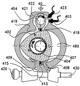
Fig. 4 illustrates a preferred embodiment of the present invention,
wherein a compression ignition (C.T.) engine generally indicated at 40
comprises a rotor housing 401 divided into two volumes by means of two
buffer seals 404 and 404'. Two separate contact points of the contour of
rotor 402 are constantly in contact with the buffer seals 404 and 404',
respectively, in order to perform a sealing action. The outlet port 419 of
the inlet-compression volume 400 is in communication with the inlet of a
rotational combustion chamber flow controller device (CCFC) 421. At the
end of the compression cycle the compressed fluid is trapped and sealed
inside the volume of the CCFC device 421 due to the coordinated motion of
its rotor 422 that blocks the outlet port 419. As the rotor 422 continues to
rotate, it delivers the compressed fluid to the opposite side of the CCFC
where a fuel injector 423 injects a controlled amount of fuel that is ignited
by the compressed fluid temperature.
A glow plug 403 is installed in order to support a cold start. Fuel in.jection
is timed so that combustion starts at the point that the front running apex
of the engine rotor 402 (coi-responding to face B in this particular drawing)
has completely passed the i-nlet port 418 of the work-exhaust volume 480.
As the engine- rotor 402 continues to rotate due to combustion pressure
over its face B, face A performs an intake cycle and face C performs an
exhaust cycle. The CCFC rotor 422 rotates concurrently with the engine
rotor 402 in such a way that each face of the engine rotor works against a
face of the CCFC rotor in a cyclic motion. A turbo-compressor turbine inlet
is in communication with the exhaust port 408 and is fed by the exhaust
gases, which in return drive a flow compressor 415 that supports the
CA 02628714 2008-05-06
WO 2007/017867 PCT/IL2006/000911
17
intake cycle with pressurized fluid through intake port 409. As clearly
seen, the apex of the engine rotor 402 performs a complete scavenging of
the volume and exhaust gases cannot mix with intake charge due to buffer
seal 404'.
The charging (intake) cycle is continuous, without any inteiTuption in
flow. Compensation for overlap between exhaust port 408 to inlet port 409
is unnecessary since the fluid communication between the two ports is
completely blocked by the buffer seal 404'.
A complete cycle starts at the flow compressor 415 intake 420 and ends at
the. turbine exhaust outlet 430. The work sector starts at the point where
the inlet port 418 of the work volume 480 is completely passed by the
relevant apex of the engine rotor 402, wliich is about 15 to 18 after the
intersection of minor axis 410 and the top buffer seal 404, in contrast to
about 60-70 with respect to a prior art Wankel engine, as shown in Fig. 1.
The configuration of the present invention advantageously adds about 42
to the working sector at this point, as well as a substantially equal
addition towards the end of the working sector whereby the exhaust port
408 is . to be exposed by the relevant_ap.ex of the engine_rotox:, _at_ about
15
to 18 before the intersection of minor axis 410 and the bottom buffer seal
404'. All together, the effective work sector totals approximately 144 , in
comparison to about 60 achieved ivith the prior art Wankel system as it
seen in Fig. 1. It will be appreciated that the calculated work sector of the
present invention is greater than the maximum work sector of prior art
Wankel engine, which is only 60-70 since the corresponding volume does
not increase after such a value. With respect to a prior art Wankel engine,
the work sector of the engine of the present invention is actually doubled
since the volume increases within a sector of 120 .
CA 02628714 2008-05-06
WO 2007/017867 PCT/IL2006/000911
1S
In addition, it can be clearly seen in the present invention that from
begimzing to end, the work cycle combustion pressure applies a force to the
rotor which causes the latter to rotate in only one rotational direction.
Since the combustion pressure is limited to the work sector defined by the
buffer seal across the centerlirie of the minor axis, a unidirectional force
is
applied. A comparison to prior art system is given in Fig. 2 wherein it can
be seen that the force applied by the combustion pressure at the beginning
of the cycle induces rotation in equally opposed and negating rotational
directions. The situation improves as the rotation continues until after
about 60 where all the force is directed to the desired rotating direction,
but then, the work cycle is near completion and the remaining pressure is
negligible.
Fig. 5 illustrates another embodiment of the invention in the form of a
spark ignition (S.I.) engine, which is generally indicated at 50, and
comprises all of the features described above, mutatis mutandis, with the
following differences: A fuel injector 523 is situated at the CCFC 521 at its
first chamber, at the compression side upstream to its combustion side,
whereat a spark plug 503 is installed. The fuel injector is positioned at the
compression_side in order to leave tinle_.for. effective mixing of the
fueLan.d
air prior to combustion. Additionally, the compression ratio of an S.I
engine is lower than that of a C.I. engine.
With reference to Fig. 6, another embodiment of the present invention is
illustrated in the form of a continuous combustion engine, which is
generally designated by 60 and comprises all of the features described
above, mutatis mutandis, with the following differences: The engine
system of Fig. 6 comprises a rotor housing 601, optionally a multiple rotor
housing that contains more than one rotor, buffer seals 604 and 604',
potentially more of each in case of multiple rotor housing, in order to
divide each housing into two separate volumes along its minor axis. One
CA 02628714 2008-05-06
WO 2007/017867 PCT/IL2006/000911
19
or more rotors 602 perform volume changes for the positive displacement
cycles, as well as to use its peripheral contour for the constant contact
with the buffer seals in order to perform a sealing action. A turbine inlet of
a free shaft gas turbo- compressor 615 is pneumatically con.n.ected by its
turbine to the exhaust port 608 of the work-exhaust volume 680 and the
outlet port of its compressor is directly connected to inlet port 609 of the
intake-compression volume 600. The function of the gas turbine
compressor is to increase the fluid pressure that enters the combustor 642
so that increased efficiency and power output are gained. The inlet port of
a flow-controller device 621 is mounted on top of the outlet port 619 of the
intake-compression volume 600.
The compressed fluid (usually air) from the turbo-compressor 615 is
further compressed inside the volumetric device of the engine and enters
the flow controller 621 chamber and is transferred to the combustor 642
by means of rotor 622 that is synchronized with the engine rotor 602. Due
to the synchronization, the rotor 622 serves also as a buffer, preventing
the combustion pressure from returning upstream, back into compression
sector. The delivered compressed fluid flows downstream towards the
combustor via - a_ flow regulator unit 640 that responds to an automatic
airflow sensing system 641 in order to stabilize the airflow into the
combustor 642. A fuel injector 623 and initial igniter 603 are installed in
the combustor 642. Airflow data for fuel metering is supplied to the fuel
injection system (not shown). The initial igniter 603 is only for the purpose
of starting the engine, which later operates at a continuous combustion
cycle. As the engine parts are effectively cooled, high operational
temperatures can be supported such that substantial stoichiometric
combustion can be achieved, thereby simplifying the design of combustor
642 and improving its efficiency and output in comparison to a gas
turbine. Another improvement compared to a gas turbine is the high
flexibility of the present invention due to the volumetric cycle and static
CA 02628714 2008-05-06
WO 2007/017867 PCT/IL2006/000911
pressure, resulting in operational characteristics that are similar to that
of internal conlbustion volumetric engines, and at the same time having a
power density, power to weight ratio and density compensation
characteristics on the scale of a gas turbine. Additionally, the plurality of
volumes, namely rotors, housings, etc. can contribute to a smoother engine
operation and stability of fluid flow.
Fig. 7 shows another embodiment of the present invention, which is
generally designated by 70 and is a multiple rotor, continuous combustion
flow engine, which is similar to engine 60 of Fig. 6, shown according to an
exemplary arrangement. The operation and design principles suggested in
Fig 6 can be seen in Fig. 7 m.utatis nzutandi.s, wherein a plurality of rotors
702 are shown together with direct fuel injection by means of a
corresponding fuel injector 723 and initial igniter 703 into the expansion
volume 780, into which the corresponding discharge conduit 718 of CCFC
722 is introduced without any combustor due to a suitable ratio of fuel and
air mixture.
Fig. 8 is a schematic side view of the embodiment of Fig. 7 wherein an
engine shaft driven, flow compressor 890 is added to the embodiment,
thereby providing another embodiment of the present invention in order to
create a multiple stage flow compressor for the purpose of increasing the
pressure of the charged fluid.
Compressor 890 is marked by a dotted line, indicating it as an optional
feature, since the volumetric units, according to the present invention, are
capable of a very high compression ratio (higher than 70 at any K factor).
However, a flow compressor is capable of delivering a much higher
quantity of fluid, and therefore, in actual design, a combination of a
volumetric compressor and flow compressor is feasible.
CA 02628714 2008-05-06
WO 2007/017867 PCT/IL2006/000911
21
The cycle of the system shown in Fig. 8 begins at the intake 891 of the
engine shaft driven, flow-compressor 890, which feeds the compressor of
the free shaft turbine compressor 815, directly through conduit 892 or via
an intercooler (not shown) through port 820. The compressor of the free
shaft turbine-compressor 815 further compresses the fluid and delivers it
directly to the volumetric device 801 through conduit 840 or via an
intercooler (not shown). After furtlzer compression at the volumetric unit
801, the compressed fluid is delivered by the flow controller 822 into the
combustor through the flow regulator (similar to combustor 642 and flow
regulator 640 of Fig. 6).
Flow controller 822 is synchronized through its shaft 850 with the engine
main shaft 860 by means of transmission 855. After expansion in the
volumetric device at volume 880, the remaining pressure of the fluid
enters the turbine of the free shaft turbine-compressor unit 815 via
conduit 841, and a compression of the intake fluid is returned by the
compressor. The burnt fluid is discharged to the atmosphere through the
turbine outlet 830.
By employing such a flow engine-enibodiment, which is essentially a built-
in multi-fuel system, applications considered heretofore as being not
suitable for volumetric combustion engines, due to poor power to weight
ratio, fuel type limitations, and sensitivity to altitude (density
compensation), may now be feasible. Additionally, a high efficiency and
output through a wide range of engine velocity, due to the volumetric cycle
which occurs under static pressure, may also be achieved. Also, the
components of the system that are effectively cooled may operate at a
temperature much less than the ma-imum cyclic temperature. As a result,
the cyclic temperature may be higlzer, thereby enabling a higher cyclic
efficiency in comparison with a gas turbine.
CA 02628714 2008-05-06
WO 2007/017867 PCT/IL2006/000911
22
With reference to Fig. 9, another embodiment of the present invention is
described that demonstrates the way that improvements of the present
invention can be adapted by prior art systems, in order to achieve higher
performance, efficiency and better adaptability to common and new,
potential, applications. An engine is generally indicated by 90, showing
the adaptability of a low K factor (the ratio of the rotor radius to
eccentricity). A low K factor is significant in terms of influencing the
engine configuration since a lower K factor allows for a smaller engine size
and weight for a given swept volume. With the benefit of a low K factor,
drawbacks associated with a prior art Wankel engine, such as a low
compression ratio and an excessively sharp lining angle of the apex seal
over the internal contour of the rotor housing, may be overcome. Most
prior art Wankel engines have a K factor which is higher then 6 (usually
around 7 for S.I. engines and around 10 for C.I engines).
In Figs. 9A-E, the rotor 902 and the rotor housing 901 are shaped in
accordance with a K factor of 4, demonstrating an engine compactness
that can be achieved. The active volumes are relatively large, the rotor
shape is simple, and the rotor weight is less then rotors of a higher K
factor_witli-the same capacity._Furthermore,_most of the rotor mass can be
cooled by means of the large passage 959 forined in the eccentric shaft 953
while the far apex area is cooled by means of a narrow passage 952 formed
in the vicinity of a corresponding apex of the rotor, thereby eliminating the
mass flow of cooling oil inside large passages in the rotor, known as
dynamic balance, as well as center rotor sealing problems, associated with
prior art engines. An additional advantage of a low K factor is,
surprisingly due to the larger eccentricity, which normally should decrease
rotational velocity and increase torque, that the rotational velocity may be
kept as high as, or even higher than, prior art engines with higher K
factors while maintain.ing an increased torque, due to a significant
decrease in the rotor mass.
CA 02628714 2008-05-06
WO 2007/017867 PCT/IL2006/000911
23
Buffer seals 904 and 904' shown in Figs. 9A-E are situated on the two
ends of the minor axis, which is the axis dividing the internal
epitrochoidal contour into two equal halves through its narrowest section
corresponding to the central lobes.
In all embodiments of the present invention, the rotor is shaped in such a
way that, while rotating, its circumferential contour as well as its apexes
are permanently at a constant distance (gap) from the internal lobe tips of
the rotor housing at every given point. As a result, buffer seal 904 and
904' that are situated exactly at those two points facing the rotor contour
are in permaneiit contact therewith and are theoretically motionless. In a
later depiction it will become clear that the pressure applied to the buffer
seals is also constant and adjustable. In most of the embodiments of the
present invention, the rotor is not equipped with apex seals due to two
major factors. Firstly, when the relevant apex of rotor 902 passes inlet
port 918 which leads from the combustion chamber to the work-exhaust
volume, the rotor 922 of the CCFC device blocks any upstream
backpressure through the combustion chamber and the CCFC device. At
the.same time, the buffer seal 904 blocks any backpressure between the
rotor housing volumes 900 and 980. Secondly, the gap between the rotor
apex and the rotor housing can be made extremely small such that the
apex is nearly in contact with the housing. The rotor 902 is equipped with
side seals and the only possible gas leakage is at the small gap between
the rotor apexes to the rotor-housing contour The outlet of the work-
exhaust volume 980 is connected to the turbine side, inlet port of a high-
pressure turbo-compressor (not shown) and as a result, every amount of
downstream leaking gas is used by the turbo-compressor. This, in return,
increases the inlet air quantity and pressure. In certain designs, a
relatively wide gap should be made in order to achieve a higher part of the
turbo-compressor in the charging process. As for the intake-compression
CA 02628714 2008-05-06
WO 2007/017867 PCT/IL2006/000911
24
volume 900, the narrowest possible gap should be allowed between the
rotor apex tips and the rotor-housing contour, in order to miiiimize
upstream leakage. In any case, leakage has very little significance since
the fluid consists of clean air unmixed with fuel and is partially balanced
by the, relatively high pressure of the turbo-compressor. For the
continuous-flow, continuous-combustion embodiments of the present
invention the upstream and, downstream, leakages are of minor
significance or no significance at all. due to the flow line of close to
constant pressure from inlet to outlet ports. Nevertheless, an apex seal is
shown for non-turbocharged systems (Figs. 10A-C and Fig. 11D), which
can cope with the passage over the buffer seals 904 and 904' at the rotor
housing and vise versa, a buffer seal which can cope with the passage over
the apex seal.
An enlarged cross sectional view of the buffer seal 904 is shown in Fig. 9B.
All of the principal components are shown, including the apex tip of the
engine rotor 902 that is in contact with seal 904. The seal 904 is placed in
its housing 961 and is guided by a linear slide path. The base of the seal is
mechanically attached to a spring membrane 962 that is tightly affixed to
the_housing 961._A channel associated with the inner volume of the engine
is formed above the membrane 962, and a chamber 967 is formed below
membrane 962. A partition wall 964 separates chamber 967 from a similar
chamber 967A directly therebelow. Chamber 967A is also blocked by a
spring membrane 963 that is tightly affixed to the housing 961. A space
966 in communication with the inner volume of the engine by means of a
drilled passage 965 is formed under the second membrane 963. A gauged
drill 960 is formed within the partition wall 994 between the two
membranes 962 and 963. The function of the drill 960 is to prevent the
bounce tendency of the buffer seal caused by engine operation conditions,
such as a wide spectrum of vibrations, sudden changes of speed and
pressure, foreign solid particles etc. Oil is forced to pass between the two
CA 02628714 2008-05-06
WO 2007/017867 PCT/IL2006/000911
chambers througli the small diameter hole that suppresses the tendency of
the seal and spring membrane to bounce, resulting in a tighter and more
stable sealing. In large engines with correspondingly large seals, a hole
that is too small can cause a response by the seal that is too slow, which
can cause mechanical damage, excessive wear and even breakage. A hole
that is too large may not absorb the entire spectrum of possible vibrations.
For bigger engines with bigger seals, a hole of larger diameter witll spring
loaded restrictor valves 995 will give the appropriate solution. An oil
pressure inlet 969 is situated in the upper chamber 967 and an oil
pressure outlet 968 is situated in the lower chamber 967A. Similarly, the
inlet may be situated in lower chamber 967A and the outlet may be
situated in upper chamber 967. The oil pressure outlet is connected to a
pressure relief valve 990 that is adjustable or pre-adjusted and set to a
pressure level that corresponds to the designed contact force of the seal
with the peripheral surface of the rotor.
Oil enters into chamber 967 through inlet 969, flows into chamber 967A
through hole 960 and then continue to flow out of chamber 967A through
outlet 968 of the adjustable pressure relief valve 990. Oil circulation under
regulated pressure cools the buffer seal and ensures permanent contact at
constant pressure with the rotor contour. The pressurized oil in the
chambers 967 and 967A also lubricates the seal tip. The seal can be made
of porous synthesized metal through which the oil can penetrate to the
seal tip end in such a way that a sufficient amount of oil will permanently
lubricate the contact area between the buffer seal and the rotor contour.
Membrane 962 is bored with small diameter holes 964 wi.thin a region
thereof which connects the base of buffer seal 904, in order to enable
pressurized oil to penetrate to the seal. Alternatively, if seals are not made
of porous material, small drill holes 970 can be made to be used as
conduits to transfer oil to the tip of the seal. The quantity of oil can be
restricted by fixing restrict nozzles 971 inside the drills.
CA 02628714 2008-05-06
WO 2007/017867 PCT/IL2006/000911
26
Fig. 9C illustrates the buffer seal assembly shown in Fig. 9B in a situation
where the engine is not running and the seal 904 is loaded only by the
preload tension of the membrane spring 962. This is a situation that is
sufficient for the starting of the engine.
Fig. 9D illustrates the buffer seal assembly shown in Fig. 9B in a situation
where the engine is running and oil pressure is supplied to chambers 967
and 967A. The oil pressure level is controlled by the relief valve 990,
which determines the seal contact force wi.th the rotor peripheral contour
by controlling the pressure level. In practice, the pressure regulator can be
located outside of the engine so that the contact pressure of the buffer
seals can be controlled at any time, for development and testing purposes
or for achieving the best performance in normal use.
Fig. 9E illustrates how the contact pressure between the seal 904 and the
peripheral contour of rotor 902 can be kept at a constant level by
channeling the engine work pressure into both of its sides. The equalized
pressure eliminates any influence of the engine internal pressure on the
buffer seals contact pressure. with_ the rotor regardless of the _ engine
internal pressure level.
With reference to Fig. 10A, an embodiment of the rotor apex seal is shown
which is desirable in conjunction with normally aspirated engine systems
(i.e. witlzout a turbo-compressor) but can also function with every other
embodiments described above. The outer part of seal 1006 is shaped as an
integral part of the engine rotor 1002 apex and capable of sliding in and
out as needed to achieve the permanent contact with the rotor housing
inside contour. The outer congruence between the seal boundary to the
rotor is beveled as can be seen in Fig. 10C, which is a front view of the
rotor 1002 and the apex seal 1006. The beveled congruence is so utilized in
CA 02628714 2008-05-06
WO 2007/017867 PCT/IL2006/000911
27
order to ensure that the apex seal passes over the stationary buffer seal in
a"sliding' point of contact rather than at a full transverse contact. The
apex seal of Fig. 10A is also designed to eliminate the centrifugal force
effect, using two different means, which can be combined, or used
separately.
One means for preventing the influence of centrifugal force is the guide
1064. The plane of guide 1064 is inclined toward the rotational direction of
the engine, in relation to the radial axis 1070 of the rotor 1002 as shown.
In this situation, the centrifugal force that acts on the apex seal is split
into two vectors. As shown in Fig. 10A, one vector forces the seal towards
the ejection direction and the other forces the apex seal slide block 1066 in
the direction of the wall of the guide 1064. If the inclination angle of the
guide 1064 is, for example 45 , then the force is split into two equal
vectors, which means that only 50% of its total value becomes an effective
contact force on the seal. The inclination angle of apex seal 1006 in the
direction of rotation eases the retreat of the apex seal when needed during
operation and eliminates the sizing effect that occurs with perpendicular
apex seals. A flat undulated spring 1062 situated under the apex seal
supplies_the:basic contact pressure.
The centrifugal force upon the apex seal increases as a squared ratio of the
velocity, and at high engine velocity the centrifugal force can reach a
destructive level even with use of the aforementioned inclined guide 1064.
The solution for a total balance of the centrifugal force is by means of a
counterweight. A counterweight 1007 is inserted within the cavity 1008
having a pivot line (fulcrum) 1065. The counterweight 1007 is engaged
with the apex seal-sliding block 1066 by means of lever arms 1068 that
extend toward the other side of the pivot line (fulcrum) 1065. The lever
arms 1068 are inserted into coi responding holes 1060 of the apex seal-
sliding block 1066, as shown in greater detail in Fig. 10B, and protrude
CA 02628714 2008-05-06
WO 2007/017867 PCT/IL2006/000911
28
from the pivot line 1065 when the engine is idle. When the engine is in
operation, the lever arms 1068 are forced towards the pivot line 1065 and
the counterweight 1007 is held in place within the longitudinal walls of
cavity 1008. The counterweight 1007 can move inside the cavity 1008 in
two directions, namely, radial motion along radial axis 1070 towards and
away from the center point of the rotor. As the rotor 1002 rotates at any
given speed, the apex seal 1006 and the counterweight 1007 rotate
together, reaching centrifugal force of similar value and in the same
direction. As the counterweight 1007 coincides with fulcrum 1065, all of its
centrifugal force beyond the fulcrum 1065 is forced towards the opposite
direction and transferred to the apex seal 1006 by means of the lever arms
1068 and their respective holes 1060. The desired work pressure can be
applied to the apex seal by one or more of the following factors: spring
pressure, oil pressure or engine work pressure.
With reference to Figs. 11A-C, another embodiment of the apex seal is
shown and comprises all of the features described in the previous
embodiment (Figs. 10A-C) mutatis mutandi.s, with the following
differences: In Figs. 11A-C, the apex seal 1066 is flat and rectangular,
similar to a prior art _seaL shape. The_countervcreight_ 110_7 is engaged with
the flat apex seal-sliding block 1106 by means of lever arms 1168 that
extend toward the other side of the pivot point (fulcrum) 1165. The lever
arms 1168 are inserted into corresponding holes 1160 at the apex seal-
sliding block 1106. A flat undulated spring 1162 situated under the apex
seal supplies the basic contact pressure.
Fig. 11D shows the embodiment of a buffer seal which functions in a
similar way as the rotor apex seal of Figs. 10A-C The outer part of seal
1114 is shaped as an integral part of the engine minor axis lob of the rotor
housing 1112 and capable of sliding in and out as needed to achieve the
permanent contact with the rotor contour. The outer congruence between
CA 02628714 2008-05-06
WO 2007/017867 PCT/IL2006/000911
29
the seal boundary to the minor axis lob is beveled as can be seen on the
seal 1114 as in its separate drawi.ng. The bevel 1115 of the seal is in
congruence with the bevel in the housing and it is so utilized in order to
ensure that the apex seal of the rotor passes over the stationary buffer
seal in a"sliding' point of contact rather than at a full transverse contact.
Figs. 12A-F shows a rotary volumetric displacement device generally
designated by numeral 120, which overcomes the disadvantages involved
with the complex eccentric rotational motion of prior art Wankel rotary
engines. The embodiment depicted in Figs. 12A-F schematically illustrates
each rotor of a fully rotational concentric volumetric displacement device
that complements the improvements described above rnutati,s mutaaz,dis.
The engine shown in Fig. 12A comprises a housing 1201A that
accommodates the intake compression volume 1200, a housing 1201B that
accommodates the work (expansion)-exhaust volume 1280, a shaft 1260A
that carries rotor 1202A at one end and rotor 1202C at the other end,
wherein rotor 1202A and rotor 1202C are in an opposite orientation and
rotate about shaft 1260A. A second shaft 1260B carries another pair of
rotors, r.otor_ 12.02B_at .one_end and rotor 1202D at the other end, wherein
rotor 1202B and rotor 1202D are in an opposite orieiztation and rotate
about shaft 1260B. A CCFC 1228 is placed between housing 1201A and
housing 1201B, alongside the rotor housing at a parallel axis, or within
the engine rotor housing while sharing the same central engine rotor
shaft. The CCFC un.it is situated on the top of the two housings sa that the
outlet port 1219 of housing 1201A is in cominunication with the inlet of
the CCFC unit 1228 and inlet port 1218 of housing 1201B is in
communication with the outlet port of the CCFC unit 1228. A front
schematic view of displacement device 120 is shown in Fig. 12D, and a
side view of the same is shown in Fig. 12E. Inside the CCFC unit 1228, an
oval shaped rotor 1222 concentrically rotates about shaft 1250 in
CA 02628714 2008-05-06
WO 2007/017867 PCT/IL2006/000911
synchronization with shaft 1260A and shaft 1260B, which are also
mutually engaged by means of gears 1265 and 1265A. Fuel is sprayed into
volume 1226, which serves as a combustion chamber, by means of injector
1223 and is ignited by the temperature of the compressed air when a C.I.
engine is employed or by sparkplug 1203 when an S.I. engine is employed.
As combustion occurs at volume 1226 of CCFC unit 1228 and expansion
occurs at work-exhaust volume 1280, volume 1229 is charged with a fresh
charge of compressed fluid continuously in a cyclic process.
In order to prevent the burnt gases in volume 1226 and volume 1280 from
returning to the compression bank of the device a seal 1204 is situated at
the downstream end of the volume 1226 (Fig 12A). The operating pressure
for the seal 1204 is obtained from the engine lubrication system, whereby
oil pressure supplied through the drill hole 1262 is delivered to plunger
1263, which is connected by means of a connecting rod 1264 to seal 1204,
as shown in Fig. 12B. Alternatively, a spring-loaded seal by means of
spring 1266, or a combination of spring 1266 and oil pressure can be used.
A turbo-compressor 1215 is added to the device in order to increase output
and efficiency. Inlet port 1241 of turbine 1227 is in communication with
exhaust (outlet) port 1208 of work-exhaust volume 1280, whereby exhaust
gases are discharged into the turbine 1227 which in turn drives the
compressor 1226 that charges volume 1200 through conduit 1240. The
complete cycle begins at the intake 1220 of compressor 1226 and is
completed at the outlet 1230 of turbine 1227.
Fig.12C shows a centrifugal band seal system of this embodiment, for the
sealing of the two rotors. An are shaped metal seal 1298 is inserted into
cavities 1299 and 1299A formed within rotor 1202 in such way that most
of its weight is suspended over the rotating center of shaft 1260. During
rotation, seal 1298 is forced out of the center due to centrifugal force. The
movement of the seal causes contact with the rotor circumference and
CA 02628714 2008-05-06
WO 2007/017867 PCT/IL2006/000911
31
causes sealing to take place. Siniilarly seal 1298 is mounted on rotor
shafts 1260A and 1260B, within cavities formed wi.thin each rotor, in
order to achieve an effective sealing operation.
Further advantages of the embodiment shown in Figs.12A-E include:
a) a work sector of 180 in contrast to a work sector of 60 for prior
art Wankel rotary engine;
b) two work cycles of the present embodiment are achieved from a
full rotation (360 ) of the engine, as opposed to one work cycle for one
rotation (360 ) of a prior art Wankel rotary engine;
c) a fully concentric rotation takes place which simplifies the desigii
and construction of the engine and eliminates serious balancing problems
and engine speed limitations, in contrast to prior art Wankel engines
which have an eccentric shaft resulting in complex motion of the geared
rotor; and
d) the engine shaft and the rotors rotate at the same speed in the
present embodiment, while the engine shaft rotates three times as fast as
the rotor in prior art Wankel engines.
Fig._12F_illustrates_an_arrangement similar to the one described in Figs.
12A-E, although the configuration of rotors 1272A-D of Fig. 12F is
different than rotors 1202A-D of Fig. 12A. Each of the rotors 1272A-D is
curvilinear and has at least one convex engagement portion 1273 and one
concave engagement portion 1274, which are so shaped that a convex
engagement portion 1273 of one rotor is adapted to be seated in a concave
engagement portion 1274 of a corresponding rotor upon rotation of the two
rotors. Accordingly, such engagement of two corresponding portions 1273
and 1274 constitute isolation means, by which fluid remaining between
said two corresponding portions 1273 and 1274 is squeezed from the gap
therebetween so as to prevent the mixing of a fresh charge with, the
residue of the previous charge. The rotors of Fig. 12F provide an increased
CA 02628714 2008-05-06
WO 2007/017867 PCT/IL2006/000911
32
sealing action since they have a much larger overlap sector as compared to
those of Fig. 12A and they also allow a larger volume charge to be
introduced than those of Fig. 12A, when the rotors of Figs. 12A and 12F
are of substantially equal length and width, due to the different shape of
rotors 1272A-D which occupy a correspondingly smaller volume within the
rotor housuig. Also, the convex engagement portions 1273 of rotors 1272A-
D of Fig. 12F have a shorter circumferential dimension than that of rotors
1-060A-D of Fig. 12A, resulting in an increased open sector of the inlet
ports so that an increased charge may be introduced into the rotor housing
in order to utilize the additionally available volume. On the other hand,
the rotors of Fig. 12A are capable of a higher compression ratio than those
of Fig. 12F since a smaller unoccupied volume remains around the inlet
port, as compared to the rotors of Fig. 12F. The designed compression ratio
is nevertheless a function of the relation between the larger diameter to
the smaller diameter of the rotor. Any compression ratio of modern S.I and
C.I engines is easily achievable with the engines of Fig. 12A and Fig. 12F.
Although CCFC 1281 is shown to have four concave walls 1282, it will be
appreciated that the CCFC of Figs. 12A and 12F may be embodied by any
CCFC of the present invention, including a variable compression-ratio
device.
Figs. 13A-I demonstrates a nine step cycle of the embodiment of Figs. 12A-
F, wherein each of the steps A-I illustrates the angular displacement
associated with- sequential engine rotation of about 45 . For purposes of
clarity, the arrows and the black spot at one apex of each rotor indicate
the relative motion of each component of the engine.
Fig. 14A shows an embodiment of a flow controller device generally
designated by 1400 having 3 hemispherical combustion chambers 1418,
one for each of the engine rotor banks. The chambers are equipped with
cooling fins 1427 aizd are sealed by means of sealing rings 1420 in order to
CA 02628714 2008-05-06
WO 2007/017867 PCT/IL2006/000911
33
seal the gap between the rotor 1417 and the rotor housing 1416 around
the opening of the combustion chanlber.
Fig. 14Bis a schematic side view of Fig. 14A, which shows the
arrangement of the inlet ports 1424 and the outlet ports 1412 of the flow-
controller device in order to explain how the remaining of the compression
pressure can blow out the residual burnt gas from the coinbustion
chamber 1418 within a narrow sector of overlapping at the end of the
compression stroke and close to the end of the expansion stroke,
corresponding to a time at which the compression pressure is 1-Agher than
the expansion (work) pressure. A minor extension port 1430 from the
outlet 1412 protrudes towards the inlet port 1424 to such a distance that
enables a short overlap of the combustion chamber 1418 over the
extension port 1430 and the small exposed area 1431 of the iiilet port
1424. Since compression pressure is at its maximum level and the
expansion pressure is substantially at its lowest level, a short blast of
compressed air purges the residual combustion gas from the combustion
chamber. This process occurs after the compression side of the combustion
chamber is already charged and port 1412 is no longer exposed, so that the
air which is used_ _for_ the purging action__may advantageously be the
relatively small quantity which is trapped within outlet port 1412.
With reference to Figs. 15A and 15B another embodiment of a CCFC is
illustrated. The illustrated CCFC designated by 1500 is capable of
clianging the compression ratio during operation, in response to the air
density or any other considered factor such as fuel type, cold weather
start, operation at very cold weather conditions etc.
The engine rotor 1527 rotates within the rotor housing 1513, e.g. in a
clockwise direction as illustrated, and compresses air in the compression
volume 1511. Th.e compressed air is delivered into the corresponding
CA 02628714 2008-05-06
WO 2007/017867 PCT/IL2006/000911
34
combustion chamber, e.g. combustion chamber 1518A, of CCFC 1500 via
its inlet port 1512. The volume of chamber 1518A is at its maximum value
since the piston 1514 is at the bottom of its stroke. The stroke is
c.ontrolled
by means of a bi-directional (double walled) cam 1522 disposed
substantially in the center of CCFC 1500 and of a cam follower 1521
integrally formed with the piston body at the bottom of each piston. As
engine rotors 1527 and CCFC rotors 1517 continue to rotate, an engine
rotor 1527 completes the compression stroke and the iiilet port 1512 is
closed by a flow-controller rotor 1517. As said flow-controller rotor 1517
continues to rotate, the corresponding piston 1514 is pushed by its cam-
follower 1521 and cam 1522 towards the top of its cylinder, thereby
further increasing the compression pressure. The pressure increase of
combustion chamber 1518A is terminated when the outlet port 1524
leading to the expansion volume 1526 of the engine is exposed following
subsequent rotation of a flow-controller rotor 1517 and the fluid content of
the combustion chamber 1518A bursts into the expansion volume 1526.
The cam 1522 which causes the travel of the piston 1514 is mounted upon
a centric shaft 1523. The said centric shaft 1523 is capable of performing
clockwise and counterclockwise angular motion and is .conntrolled. by a
lever 1519, or any other similar means which is controlled by automatic or
manual apparatus having suitable sensitivity for controlling the motion of
centric shaft 1523. When the lever 1519 turns the centric shaft 1523 and a
cam 1522 in a counterclockwise advancing direction, the corresponding
piston 1514 will move further toward the cylinder top before the outlet
port 1524 will be exposed by the flow-controller rotor, causing the pressure
inside the corresponding combustion chamber 1518 to increase. When the
lever 1519 turns the centric shaft 1523 and a cam 1522 to a clockwise
retracting direction, the outlet port 1524 will be exposed to the combustion
chamber 1518 while the corresponding piston 1514 is in a lower position
CA 02628714 2008-05-06
WO 2007/017867 PCT/IL2006/000911
inside its cylinder, and therefore a lower pressure will be generated inside
the corresponding combustion chamber 1518.
When a C.I. engine is employed, the fuel is injected into a combustion
chamber 1518 at an optimal predetermined time to let it burn completely
before being exposed to the outlet port 1524. The air pressure level at the
time of fuel injection is of great importance with respect to cold start and
regular operation, particularly when the ambient air is of low density,
such as commonly found at high altitudes or during very cold weather
conditions.
When an S.I. engine is employed, a spark ignites a mixture of air and fuel
at an optimal predetermined time so that the entire, or a majority of, the
mixture may undergo complete combustion before being exposed to the
outlet port 1524. With respect to an S.I. engine, the compression ratio can
be automatically adjusted in response to parameters such as the fuel
octane ratio, air density and ambient temperature by means of a knock
sensor, which can control the combustion ratio variation apparatus (not
shown) adapted to operate lever 1519 in response to the aforementioned
par.ameters, in order to maintain the engine at top performance without
any risk of damage. CCFC 1500 is so designed that the apex of the cam
1522 leads the pistoii to the top of the cylinder. After a coinbustion
chamber 1518 is exposed to the outlet port 1524, the piston 1514 continues
to move upward in its cylinder until reaching the top thereof, causing all
the burnt gas to be discharged from the combustion chamber. By this
operation, two important goals are ach.ieved: 1)all of the burnt air-fuel
mixture participates in the expansion work producing process and 2)
residual burnt gases do not remain in the combustion chainber at the
commencement of a new cycle. As rotation continues, the piston 1514 is
lowered within the cylinder by the external wall of cam 1522 in order to
CA 02628714 2008-05-06
WO 2007/017867 PCT/IL2006/000911
36
increase the combustioii chamber volume to a maximum value in
preparation to a new cycle.
Figs. 16A and 16B illustrate another embodiment of a controlled
compression-ratio CCFC, which is designated by 1600. CCFC 1600
functions similarly to CCFC 1500 of Figs. 15A and 15B and have the same
advantages. CCFC 1500 and CCFC 1600 differ in terms of the cam and
cam follower configuration. Eccentric cam 1622 of Figs. 16A and 16B is
unidirectional, and is adapted to push a piston 1614 by means of the
corresponding cam-follower 1621 only towards the top of its cylinder. A
piston is returned downwardly by means of a corresponding set of
preloaded springs 1630 and of the pressure of the compressed gas within
the combustion chambers 1618. A piston is forced towards cam 1622 firstly
by the compression pressure and subsequently by the combustion
pressure. The gas pressure together with the applied load of the springs
1630 is adapted to overcome the centrifugal force acting on the pistons
1614 upon rotation of the rotor 1617. Also, Fig. 1 GB shows the way the
pistons are arranged inside the rotor in an inclined angle a in order to
minimize the general size of the whole flow-controller device. By inclining
cam-followers 1621 with respect - to a corresponding._set of- springs 1630,
the pistons 1614A-C can be placed closer to one another, resulting in a
more compact CCFC.
Similar to CCFC 1500 of Fig. 15A, the combustion ratio is controlled by
the angular motion of the cam 1622, which is connected by means of shaft
1623 to lever 1619. A counterclockwise angular motion of lever 1619 and
cam 1622 will increase the compression ratio since the pistons of the
combustion chambers will reach a higher point in the cylinder before the
outlet port 1624 will be exposed, and vise versa, a clockwise angular
motion of lever 1619 will decrease the compression ratio since the
exposure of outlet port 1624 will occur when the piston 1614 is in a lower
CA 02628714 2008-05-06
WO 2007/017867 PCT/IL2006/000911
37
point in its cylinder. This description is valid only when the CCFC rotor
1617 and the engine main rotor are rotating in a clockwise motion. In case
of counterclockwise rotation of said rotors, the operation of the engine is in
an opposite sequence.
Fig. 17 illustrates another embodiment of a controlled compression-ratio
CCFC, which is designated by 1700. In this embodiment, the motion of the
pistons 1714 witlun the corresponding cylinders of rotor 1728 is controlled
by means of eccentric shaft 1722 and conn.ecting rods 1733. The eccentric
shaft 1722 is integrally formed with centric shaft 1723 disposed at
substantially the center of CCFC 1700. While rotating within housing
1734, rotor 1728 causes hub 1736 to rotate by means of engagement finger
1725 in engagement with slot 1726 formed in the rotor 1728. This
engagement is so arranged in order to enable a relative linear motion of
the hub 1736 mounted on the eccentric shaft 1722 with respect to the rotor
1728 mounted on the centric shaft 1731. The centric shaft 1731 is driven
by means of geared wheel 1730. Since the hub 1736 to which the
engagement finger 1725 is attached rotates about eccentric shaft 1722 and
rotor 1728 rotates about centric shaft 1731, a relative linear motion
between the rotor..1728 and hub 1736,_the lengtli-of_whichss .substantially
equal to the eccentricity of eccentric shaft 1722, results during each
revolution of eccentric shaft 1722. Slot 1726 accommodates the linear
motion of the engagement finger 1725. The pistons 1714 are connected to
the hub by means of connecting rods 1733. While the rotor 1728 rotates
together with the pistons 1714, the latter are also linearly displaced
within the corresponding cylinders by a displacement of twice the distance
of the eccentric value of shaft 1722. The mechanism is so arranged that
the pistons are close to the upper part of the cylinder at around the sector
it reaches the output port 1724. Any angular motion of lever 1719 of the
centric shaft 1723 to which the eccentric shaft 1722 is coiunected will cause
CA 02628714 2008-05-06
WO 2007/017867 PCT/IL2006/000911
38
a change to the compression ratio in a similar fashion as the CCFC of
Figs. 15A and 16A.
Figs. 18A and 18B illustrate an embodiment of the present invention in
which the CCFC is attached in parallel fashion to the side of the main
engine housing block. In this CCFC embodiment which is designated by
1800, the orientation of pistons 1814A-C is mutually parallel to the engine
shaft 1823 and to the centerline of CCFC 1800. The cam 1822 causes a
motion of the pistons 1814A-C in a direction parallel to the engine shaft
1823. The rotational direction of the flow-controller rotor 1817 is
preferably in an opposite direction to the engine rotational direction, in
order to utilize the rotation of the engine shaft 1823 to a ma:tmum extent
and to thereby provide for a maximum duration for each cycle. A geared
wheel transmission may be used to synchronize the rotation of engine
shaft 1823 and of flow-controller rotor 1817. The engine main shaft 1823
carries a geared wheel 1831 serving as the driving gear for the driven gear
1830 of the flow-controller rotor 1817. The cam 1822, which move the
pistons by means of their corresponding cam followers 1821, is advanced
and retracted by means of the lever 1819 and shaft 1842 in order to
control the compression_r.atio,-as_des.cribed hereinabove with respect to the
embodiments of Figs. 15-17. CCFC 1800 is advantageous in terms of its
compactness and its very small effect on the general engine size.
Figs. 19A-C illustrate three different ways of driving the flow-controller
rotor 1917. Regardless of the engine- rotor and CCFC -configuration, the
transmission for driving flow-controller rotor 1917 is selected primarily
based on the type of engine. As can be seen, the three different
transmissions shown in Figs. 19A-C, respectively, are adapted to reduce
the speed of the engine shaft 1923, so that the CCFC shaft 1913 will rotate
at an angular velocity equal to that of the engine rotor 1927, which is e.g.
one-third of the velocity of engine shaft 1923. The reduced speed of the
CA 02628714 2008-05-06
WO 2007/017867 PCT/IL2006/000911
39
CCFC shaft 1913 may facilitate power output means of the engine. Each
type of transmission can transmit power to additional components of the
engine, such as oil pumps, fuel pumps, balancing shafts, etc.
The transmission 1912 of Fig. 19A is disposed at the rear of the engine
shaft 1923, wh.i.le the CCFC shaft 1913 extends in the opposite in order to
drive a propeller, or aizy other suitable component, by means of coupling
1925. The transmission 1912A of Fig. 19B is disposed at the front of the
engine shaft 1923. The transmission of Figs. 19A and 19B is of a geared
wheel type while the transmission 1910 of Fig. 19C is of a chain and
sprocket wheels, or of a toothed belt and wheels.
Figs. 20A-C illustrate one of the preferred embodiments of an engine
system, generally designated by 2000, in accordance with the present
invention in which the CCFC is integral with the main rotor 2020 of the
engine. A fixed volume combustion chamber 2018 is sealed against the
housing side wall 2015 by means of ring seals 2021. The engine rotor 2020,
as shown, performs a compression stroke inside the inlet-compression
volume 2011. Following additional rotation of the engine rotor 2020, the
inlet_to..the.. comb.us.tio.n_chamber 2018 coincides with transfer port 2012,
whereupon the compressed fluid which is usually air is transferred into
the combustion chamber 2018. Following further rotation of the engine
rotor 2020, the charged compression chamber 2018 is advanced to the
expansion-exhaust volume 2013.
The angular displacement of the compression-chamber 2018 corresponding
to a disposition at which the transfer port 2012 of the intake-compression
volume 2011 is closed and one at which port 2024 leading from the
combustion chamber 2018 into the expansion volume 2013 is exposed is
approximately 65 to 75 . During said angular displacement of the
compression chamber 2018, the relative angular and circumferential
CA 02628714 2008-05-06
WO 2007/017867 PCT/IL2006/000911
velocity of the rotor apex 2025 is reduced by approximately 33%, due to
the displacement of the rotating center of the rotor relative to the engine
shaft, as well known to those skilled in the art. During the increased time
period for the combustion process inside the combustion chamber, the
angular displacement of the engine rotor 2020 is approximately 68 while
that of the engine shaft 2023 is approximately 285 . As a result, a time
period of approximately 0.02 sec at a shaft rotation of 4000 rpm is
sufficient to allow the combustion to take place before port 2024 is exposed
to the combustion chamber 2018 and the combusted fluid to burst
therethrough into volume 2013 in order to perform useful work.
At the other end of the minor axis, the outlet of a combustion-chamber
2018 coincides with a pressure release port 2032 and said combustion-
chamber 2018 is therefore able to release the residual burnt gas therefrom
into the exhaust port 2054. Several degrees of rotation later, the
combustion chamber 2018 exposes scavenge port 2031 and for a short
period, release port 2032 and scavenge port 2031 are connected through
the combustion-chamber 2018. A turbo-compressor supplied pressurized
fluid, which is usually air delivered through port 2052, cleanses the
combustion chamber 2018 and is directed via the scavenge port 2032
towards the exhaust port 2054.
In Fig. 20C, engine system 2000 is provided with two compression
chambers 2018 for each rotor face. By employing an engine system having
two compression chambers for each rotor face, side pressure from the rotor
2020 towards the opposite housing wall 2050 is avoided, and furthermore,
a more compact compression chamber which is necessary for larger
engines may be realized.
Figs. 20D and 20E illustrate another embodiment of engine 2000 of Fig.
20B in which a side pressure inhibiting means is employed by the CCFC
CA 02628714 2008-05-06
WO 2007/017867 PCT/IL2006/000911
41
such that the side pressure is significantly reduced in Fig. 20E and is
completely eliminated in Fig. 20D. Side pressure is normally applied to
one of the side walls 2015 of the rotor housing when such inhibiting means
is not employed due to compression and combustion pressure at the
opposite side wall, thereby increasing the friction between the rotor 2020
and the housing wa112015.
In Fig. 20D, a hemispherical or similarly shaped combustion chamber
2018 which is integral witli the engine rotor 2020 and disposed at one side
thereof is in communication by means of a small-diameter bore 2030
formed in the rotor 2020 to a very shallow recess 2032 on the opposite
side of the rotor 2020. The shallow recess 2032 is sealed by means of
sealing rings 2021 in the same way as the combustion chamber 2018 is
sealed at the opposite side of the rotor 2020. The projected surface area of
the shallow recess 2032 is substantially equal to that of the opening of the
combustion chamber 2018, and the sealing rings 2021 of the combustion
chamber 2018 are substantially of the same diameter as of the sealing
rings 2021 of the shallow recess 2032. When the compression pressure
and, sequentially, the combustion pressure are generated within the
combustion chainber- 2018, the- resulting -pressure is transmitted to- the
shallow recess 2032 at the opposite side of the rotor 2020 via the bore 2030
in order to balance the side pressure generated by the compression and
the combustion within the combustion chamber. The shallow recess 2032
is needed in order to prevent the blockage of the bore 2030 by the side wall
2015. The projected surface area of the opening of combustion chamber
2018 and of the shallow recess 2032 are defined by the projected surface
area which is enclosed by an inner sealing ring 2021.
In Fig. 20E, a side pressure inhibition means is employed in order to
considerably and simply reduce the side pressure. Combustion chamber
2018 is of a completely spherical type and is disposed in the rotor 2020 at
CA 02628714 2008-05-06
WO 2007/017867 PCT/IL2006/000911
42
approximately the same location as the combustion chambers of Figs. 20A-
D. The opening 2017 of the combustion chamber 2018 is narrowed and
elongated in order to minimize its projected surface area on one hand and
to be sufficiently long on the other hand in order to cope with the fuel
injection within a given rotation sector of the rotor 2020. The projected
surface area of the open.i.ng 2017 may be about 25% to 40% of the projected
surface area which is enclosed within the circle defined by the maximum
diameter of the combustion chamber 2018. By providing such a reduction
in the projected surface area of the opening 2017, a reduction ranging from
60% to 75% of the side force generated by the compression and combustion
within the combustion chamber 2018 may be realized, since the pressure
generating by the combustion chamber is acting on a smaller projected
area. The opening 2017 is sealed against the rotor housing side wall by
means of seal 2021.
Similarly, a relatively narrow and deep combustion chamber in which the
projected surface areas of the opening and of the combustion chamber are
substantially similar may be employed.
Figs. 21-A and 21B illustrate another embodiment of an engine-system
generally designated by 2100, in which a variable compression-ratio CCFC
is integral with the rotor 2120 of the engine. As the rotor 2120 rotates, a
tiltable grooved cam 2148 controls the linear motion of the piston(s) 2114
inside the corresponding cylinders 2115 thereof formed in the rotor 2120.
The relative position of the piston 2114 in its cylinder determines the
volume of the corresponding combustion chamber 2118 and consequently
controls the compression ratio. The contour of the grooved cam 2148 is
similar in shape to the internal contour of the epitrochoidal rotor housing
2116, and smaller in size, in order to accommodate the path corresponding
to the displacement of the pistons 2114, which are located near the apexes
2125 of the rotor 2120. The grooved cam 2148 is connected to the rotor
CA 02628714 2008-05-06
WO 2007/017867 PCT/IL2006/000911
43
housing 2116 by means of sleeve 2149 having a ball joint (not shown) on
wlii.ch the grooved cam 2148 is mounted. The degree to wluch grooved cam
2148 is tilted is controlled by a mechanically operating apparatus 2140
which is responsive to sensors that detect ambient conditions such as air
density, temperature, or any otlier suitable parameters. The incremental
swinging motion of the grooved cam 2148 is transmitted to piston 2114 by
means of rocker arm 2144, which follows the path defined by grooved cam
2148, and wrist pin 2146 by which piston 2114 is connected to lever arm
2144. In addition to the wrist pin 2146, the relative angular motion
between the rocker arm 2144 and the piston 2114 is made possible by
means of pivot pin 2143 which is suitably fixed to the engine rotor 2120.
The rocker-arm 2144 changes its angular position with respect to the
tilting angle of its guiding grooved cam 2148 by means of its shaped end
2110. The grooved cam 2148 is connected to its controlling apparatus by
means of connecting rod 2142. The piston 2114 may be displaced by any
other suitable means well known to those skilled in the art for
transferring rocking motion into reciprocating linear motion. The engine
system 2100 is configured in such a way that the volume of the
combustion-chamber 2118 at a maximum value when it receives the
compressed fluid from the compression volume- and at a minimum value;
as controlled by apparatus 2140, when exposed to port 2124, in order to
transfer the combustion product into the expansion volume at the
beginning of each work stroke of the engine.
Figs. 22A and 22B illustrate another embodiment of an engine system
generally designated by 2200, in which a variable compression-ratio CCFC
is integral with the rotor 2220 of the engine, which is provided with two
chambers for each rotor face. As the rotor 2220 rotates, a double-grooved
cam 2248 controls the linear motion of the piston(s) 2214 inside the
corresponding cylinders 2215 thereof formed in the rotor 2220. The
position of the piston 2114 in its cylinder determines the volume of the
CA 02628714 2008-05-06
WO 2007/017867 PCT/IL2006/000911
44
corresponding combustion chamber 2118 and consequently controls the
compression-ratio. The contour of the disc 2248 is similar in shape to the
internal contour of the epitrochoidal rotor housing 2216, and smaller in
size, in order to accommodate the path corresponding to the displacement
of the pistons 2214, which are located near the apexes 2225 of the rotor
2220. The double-grooved cam 2248 is integral with sleeve 2249. The
motion correspondiiig to the path defined by the double-grooved cam 2248
is transmitted to a piston 2214 by means of rocker-arm 2244 and a wrist
pin 2246, by which a a piston 2214 is connected to rocker-arm 2244. In
addition to the wrist pin 2246, angular motion between the rocker-arm
2244 to piston 2214 is made possible by means of pivot pin 2243 wh.ich is
suitably fixed to the engine rotor 2220. The rocker-arm 2244 changes its
angular position with respect to the grooved path of the double grooved
cam 2248 by means of its shaped end 2210. The double-grooved cam 2248
is capable of changing the compression ratio of the engine by clockwise or
counterclockwise angular motion, similar to the engines of Figs. 15-18.
The angular motion is transmitted to the double-grooved cam 2248 by
means of its integral mounting sleeve 2249 by means of external lever
2219, a step motor 2259, or by any other suitable means. The
displaceinent_of pistons_2214_.may- be-carried out- by- any other- suitable
means well known to those skilled in the art for transferring rocking
motion into reciprocating linear motion. The engine system 2200 is
configured in such a way that the volume of the combustion-chamber 2218
at a maximum value when it receives the compressed fluid from the
compression volume and at a minimum value, in order to transfer the
combustion product into the expansion volume at the beginning of each
work stroke of the engine. Towards the end of the work stroke, the pistons
2214 are displaced to a maximum extent, in the vicinity of the top of the
corresponding cylinder 2215, so as to evacuate the remaining of the burnt
gas from the corresponding combustion chamber 2218. As the rotor 2220
continues to rotate, the pistons 2214 are retracted to their maximum
CA 02628714 2008-05-06
WO 2007/017867 PCT/IL2006/000911
volume position, or bottom dead center (BDC). In order to avoid backlash,
the pistons are loaded by means of spring 2245. It will be appreciated that
a spring loaded piston can be also be displaced by means of a single-walled
cam while the springs generate motion in the opposite direction caused by
a cam or any other similar means.
While some embodiments of the invention have been described by way of
illustration, it will be apparent that the invention can be carried into
practice with many modifications, variations and adaptations, and with
the use of numerous equivalents or alternative solutions that are within
the scope of persons skilled in the art, without departing from the spirit of
the invention or exceeding the scope of the claims.