Note: Descriptions are shown in the official language in which they were submitted.
CA 02628715 2010-03-25
FUEL CELL MOISTURE AND OFFGAS DISCHARGE SYSTEM
TECHNICAL FIELD
[00021 This invention is related to a fuel cell system and, more particularly,
to discharge
of moisture within a fuel cell system
BACKGROUND
[00031 A conventional fuel cell system may be constructed such that a fuel
cell is
positioned at the base of the system and offgas and moisture are discharged
from the fuel
cell to a gas-liquid separator that recovers the moisture from the fuel cell.
In this case, it
is necessary to discharge the moisture separated using the gas-liquid
separator outside of
the fuel cell system. However, due the placement of the fuel cell at the base
of the fuel
cell system, the fuel cell system may have to use a pump, or a similar device,
to move the
offgas and the moisture, which includes liquid water, from the fuel cell to
the gas-liquid
separator. The use of a pump, or similar device, invites defects through the
enlargement
of the construction size and complications of fuel cell system. In addition, a
pump, or
similar device, to move the offgas and the moisture between components of the
fuel cell
system may require a power supply.
SUMMARY
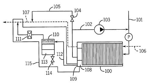
[00041 The invention relates to a fuel cell system that enables discharge of
moisture
generated by the fuel cell system based on pressure differences between
components of
the fuel cell system. This invention does not invite an enlargements or
complications of
the construction nor impose any restrictions on the layout of the fuel cell
system.
[00051 The fuel cell system includes a fuel cell that generates power by an
electro-
chemical reaction of fuel gas and an oxidant gas. The fuel cell discharges
oxidant offgas
via a cathode discharge pipe and discharges fuel offgas and moisture to an
anode drain
opening that in turn discharges the fuel offgas and the moisture to a gas-
liquid separator
via an anode drainpipe. The gas-liquid separator separates fuel gas components
and
I
CA 02628715 2008-04-29
WO 2007/010372 PCT/IB2006/001992
moisture of the fuel offgas. In addition, a throttle valve establishes a
degree of an
opening in the flow path of the fuel offgas between the gas-liquid separator
and the
cathode discharge pipe.
[0006] The throttle valve establishes a pressure difference downstream within
the anode
drainpipe to enable movement of the fuel offgas and the moisture from the
anode drain
opening to a lower pressure area of the gas-liquid separator. In this way, the
invention
enables discharging moisture to the outside of the fuel cell system by
scooping up the
moisture which was generated by the fuel cell according to the pressure
difference which
was established between the anode drain opening of the fuel cell and the gas-
liquid
separator.
[0007] In addition, the pressure difference enables the fuel offgas to flow
from the gas-
liquid separator to the cathode discharge pipe through the throttle valve. The
throttle
valve regulates the opening in the flow path in order to dilute the fuel
offgas to an
allowable concentration with the cathode offgas within the cathode discharge
pipe. In
this way, the fuel offgas may be safely released into the atmosphere.
[0008] In one embodiment, the invention is directed to a fuel cell system
comprising a
fuel cell that performs power generation by an electrochemical reaction of a
fuel gas and
an oxidant gas, a cathode discharge pipe that discharges oxidant offgas
generated during
power generation from the fuel cell, and an anode drain opening that
discharges fuel
offgas and moisture generated during power generation from the fuel cell via
an anode
drainpipe. The fuel cell system also comprises a gas-liquid separator that
receives the
fuel offgas and the moisture from the anode drain opening via the anode
drainpipe, and
separates fuel gas components and moisture of the fuel offgas, and a throttle
valve
established in a flow path of the fuel offgas between the gas-liquid separator
and the
cathode discharge pipe that restricts a flow rate of the fuel offgas. A
pressure difference
in the anode drainpipe causes the fuel offgas and the moisture to flow from
the anode
drain opening to the gas-liquid separator, and the fuel offgas to flow from
the gas-liquid
separator to the throttle value.
[0009] In another embodiment, the invention is directed to a method comprising
performing power generation by an electrochemical reaction of a fuel gas and
an oxidant
gas within a fuel cell, discharging oxidant offgas generated during power
generation from
the fuel cell via a cathode discharge pipe, and discharging fuel offgas and
moisture
generated during power generation from the fuel cell with an anode drain
opening via an
anode drainpipe. The method further comprises receiving the fuel 'offgas and
the
2
CA 02628715 2008-04-29
WO 2007/010372 PCT/IB2006/001992
moisture from the anode drain opening via the anode drainpipe, and separating
fuel gas
components and moisture of the fuel offgas with a gas-liquid separator, and
maintaining
an opening in a flow path of the fuel offgas between the gas-liquid separator
and the
cathode discharge pipe with a throttle valve that restricts a flow rate of the
fuel offgas.
The method also includes establishing a pressure difference in the anode
drainpipe that
causes the fuel offgas and the moisture to flow from the anode drain opening
to the gas-
liquid separator, and the fuel offgas to flow from the gas-liquid separator to
the throttle
value.
[0010] In a further embodiment, the invention is directed to a fuel cell
system comprising
a fuel cell that performs power generation by an electrochemical reaction of a
fuel gas
and an oxidant gas, means for discharging fuel offgas and moisture generated
during
power generation from the fuel cell to a gas-liquid separator via an anode
drainpipe, and
means for establishing a pressure difference in the anode drainpipe that
causes the fuel
offgas and the moisture to flow from the anode drain opening to the gas-liquid
separator,
and the fuel offgas to flow from the gas-liquid separator to the throttle
value.
[0011] The details of one or more embodiments of the invention are set forth
in the
accompanying drawings and the description below. Other features, objects, and
advantages of the invention will be apparent from the description and
drawings, and from
the claims.
BRIEF DESCRIPTION OF DRAWINGS
[0012] FIG. 1 illustrates the structure of a fuel cell system related to
Embodiment 1 of
this invention.
[0013] FIG. 2 illustrates the structure of a fuel cell system related to
Embodiment 2 of
this invention.
[0014] FIG. 3 illustrates the structure of a fuel cell system related to
Embodiment 3 of
this invention.
[0015] FIG. 4 illustrates one example of the open/close control of the
blocking valve in
Embodiment 3.
[0016] FIG. 5 illustrates the structure of a fuel cell system related to the
Embodiment 4 of
this invention.
[0017] FIG. 6 illustrates one example of open/close control of the blocking
valve in
Embodiment 4.
3
CA 02628715 2008-04-29
WO 2007/010372 PCT/IB2006/001992
[0018] FIG. 7 illustrates the structure of a fuel cell system related to
Embodiment 5 of
this invention.
[0019] FIG. 8 illustrates the construction of a fuel cell system related to
Embodiment 6 of
this invention.
[0020] FIG. 9 illustrates the construction of a fuel cell system related to
Embodiment 7 of
this invention.
[0021] FIG. 10 illustrates the construction of a fuel cell system related.to
Embodiment 8
of this invention.
[0022] FIG. 11 illustrates the construction of a fuel cell system related to
Embodiment 9
of this invention.
[0023] FIG. 12 illustrates the construction of a fuel cell system related to
Embodiment 10
of this invention.
[0024] FIG. 13 illustrates the construction of a fuel cell system related to
Embodiment 11
of this invention.
[0025] FIG. 14 is a flowchart that illustrates the control sequence of a fuel
cell system
related to Embodiment 12 of this invention.
[0026] FIG. 15(a) is a diagram related to the water introduction amount to a
tank related
to Embodiment 12 of this invention.
[0027] FIG. 15(b) is a diagram concerning a count of the water level
fluctuations of a
water level sensor related to Embodiment 12 of this invention.
[0028] FIG. 15(c) is a diagram concerning the operations count of a discharge
water
valve related to Embodiment 12 of this invention.
[0029] FIG. 15(d) is a diagram concerning the frequency of a gas-liquid
separator sensor
related to Embodiment 12 of this invention.
DETAILED DESCRIPTION
[0030] FIG. 1 illustrates the construction of a fuel cell system related to
Embodiment 1 of
this invention. The system of Embodiment 1 shown in FIG. 1 has a fuel cell 100
that
performs power generation, a hydrogen supply system for supplying hydrogen or
hydrogen rich gas, which is the fuel gas to fuel cell 100, and an air supply
system for
supplying air that contains oxygen, which is the oxidant gas to fuel cell 100.
[0031] Within fuel cell 100, power generation cells, including hydrogen
electrodes to
which hydrogen is supplied and air electrodes to which oxygen (i.e., air) is
supplied, are
superimposed by sandwiching and laminating electrolyte-electrode complexes. In
4
CA 02628715 2008-04-29
WO 2007/010372 PCT/IB2006/001992
addition, fuel cell 100 includes a generation part that produces electrical
energy from the
chemical energy of the electro-chemical reaction of hydrogen and oxygen.
[0032] At the hydrogen electrode of fuel cell 100, the hydrogen separates into
hydrogen
ions and electrons, the hydrogen ions pass through the electrolyte and the
electrons
generate power by passing through an external circuit, respectively moving to
the air
electrode. At the air electrode, the previously described hydrogen ions and
electrons react
with the oxygen in the air that is supplied, with water being generated and
discharged to
the outside.
[0033] A solid polymer electrolyte for the electrolyte of fuel cell 100 may
create a high
energy density, low-cost, and lightweight fuel cell system. The solid polymer
electrolyte
is comprised of a fluoride resin based ion exchange membrane and a polymer
membrane
capable of conducting ions (i.e., protons), and functions as an ion conducting
electrolyte
using saturated moisture.
[0034] The hydrogen gas supplied from the hydrogen supply source is sent
towards the
hydrogen supply pipe 101 passing through the hydrogen adjustment valve, and is
supplied
to the hydrogen electrode of fuel cell 100. At fuel cell 100, when all of the
supplied
hydrogen gas is not consumed, an anode circulation pump 103 circulates the
hydrogen
offgas discharged from fuel cell 100 without being consumed by passing the
hydrogen
offgas through the anode circulation pipe 102. Within the anode circulation
pipe 102, the
hydrogen offgas mixes with the newly supplied hydrogen gas and is subsequently
supplied to the hydrogen electrode of fuel cell 100.
[0035] Anode circulation pipe 102 includes a purge valve 104 and a purge pipe
105 on
the outlet side of fuel cell 100. Purge valve 104 is normally closed, and is
opened if there
is a detection of a reduction in cell voltage with the accumulation of clogged
water or
inactive gas in fuel cell 100. Within anode circulation pipe 102, impurities
or nitrogen
accumulate from the circulation of the hydrogen gas, and there is a reduction
in
generating efficiency of fuel cell 100 due to the lowering of hydrogen
pressure. The
hydrogen is purged from fuel cell 100 and anode circulation pipe 102 by
releasing the
purge valve 104 as needed.
[0036] The air supply system of fuel cell 100 conducts air from an air supply
pump to the
air electrode by the air supply pipe 106. Any oxygen and cathode offgas that
is not
consumed by fuel cell 100 is discharged from fuel cell 100 to outside the fuel
cell system
by the cathode discharge pipe 107.
CA 02628715 2008-04-29
WO 2007/010372 PCT/IB2006/001992
[0037] In addition, the fuel cell system provides an anode water discharge
system 115.
When fuel cell 100 performs power generation using an oxidation reduction
reaction,
moisture is generated on the cathode side of fuel cell 100. This moisture
moves to the
anode side of fuel cell 100 by the electrolyte membrane and is discharged from
anode
drain opening 109 along with the fuel offgas. Anode water discharge system 115
provides a discharge of this moisture, which includes liquid water and offgas
to the
outside of the fuel cell system. The fuel cell system also provides a gas-
liquid separator
110 and a throttle valve 111 that comprises an orifice.
[0038] Gas-liquid separator 110 is placed at a higher position than anode
drain opening
109 of anode discharge opening manifold 108 of fuel cell 100, and connects
with anode
drain opening 109 of fuel cell 100 by an anode drain pipe 112. Gas-liquid
separator 110
includes a water tank 113 that temporarily retains water on a lower part of
gas-liquid
separator 110, and a discharge water valve 114 that controls discharge of the
water
retained in the water tank 113 to the outside of the fuel cell system. The gas-
liquid
separator 110 receives hydrogen offgas and moisture that was generated inside
fuel cell
100 from the anode drain opening 109, and separates gas components and
moisture from
the hydrogen offgas. Gas-liquid separator 110 temporarily retains the
separated moisture
in the water tank 113 and appropriately discharges the retained water from the
water tank
113 by the discharge water valve 114.
[0039] The gas-liquid separator 110 is also connected to the cathode discharge
pipe 107
that opens into the atmosphere. Throttle valve 111 is established between the
gas-liquid
separator 110 and the cathode discharge pipe 107. While running the fuel cell
system, the
pressure in the fuel cell 100 is higher, 1 OKPa or more, than the pressure of
the atmosphere.
Therefore, the offgas and the moisture in the anode drain opening 109 is
sucked to the
gas-liquid separator 110 by the pressure difference between the connecting
point of the
gas-liquid separator 110 and the cathode discharge pipe 107 and the anode
drain opening
109. The throttle valve 111 works to reduce or restrict the flow rate or flow
speed of the
offgas and the moisture such that the moisture can be fully separated from gas
components in the gas-liquid separator 110. Only gas components that do not
include
moisture are moved to the cathode discharge pipe 107 via the throttle valve
111,
otherwise the discharge pipe107 may be choked by liquid water. The throttle
valve 111
works to prevent moisture from reaching the cathode discharge pipe 107.
[0040] In addition, the fuel cell system provides a system control part 120
(not shown in
FIG. 1). The system control part 120 functions as a controlling center that
controls the
6
CA 02628715 2008-04-29
WO 2007/010372 PCT/IB2006/001992
operation of the fuel cell system and provides resources, such as the CPU,
memory
device, and input/output devices for controlling operational processing using
programs.
The system control part 120 reads the necessary signals for operation of the
fuel cell
system, such as the pressure, temperature, voltage, and current obtained by
sensors (not
shown) in this fuel cell system. Based on programs read and preloaded in
internal control
logic, the system control part 120 sends commands to each component of the
fuel cell
system and includes moisture exhaust processing for the fuel cell system.
[0041] As illustrated in FIG. 1, the throttle valve 111 is positioned between
the gas-liquid
separator 110 and the cathode discharge pipe 107. Throttle valve 111 is
established so
that it is possible to maintain a pressure difference more than the sum of the
difference in
elevation L between the anode drain opening 109 and gas-liquid separator 110
in the
anode drain pipe 112. In other words, the throttle valve establishes the
following: L
(mm)/100 (kPa) + APs < AP (kPa) = P2- P1, where L is the difference in
elevation, APs is
the pressure drop in the anode drain pipe 112, P1 is the pressure within gas-
liquid
separator 110, and P2 is the pressure within the anode outlet manifold 108.
[0042] In embodiment 1, the opening of the throttle valve 111 has a circle
diameter of
0.18 mm. The diameter of the opening of the throttle valve 111 is established
so as to be
able to dilute the hydrogen offgas passing through throttle valve 111 to less
than a
combustible hydrogen concentration using the cathode offgas within the cathode
discharge pipe 107.
[0043] Embodiment 1 includes throttle valve 111 that generates a pressure
difference in
the anode drainpipe 112 between the gas-liquid separator 110 in the anode
outlet
manifold 108. By using this pressure difference, it becomes possible to scoop
up the
water generated by the fuel cell 100 and discharged from the anode outlet
manifold 108
and the anode drain opening 109 to the gas-liquid separator 110, which is
placed at a
higher location in the fuel cell system than the anode outlet manifold 108 and
the anode
drain opening 109.
[0044] Between the gas-liquid separator 110 and the anode outlet manifold 108,
it is
possible to scoop up the water by discharging the fuel offgas due to the
pressure
difference. The pressure difference is determined based on the difference in
elevation and
the pipe pressure drop of the anode drainpipe 112. In addition, it becomes
possible to
dilute the hydrogen offgas passing through the throttle valve 112 by mixing
the hydrogen
offgas and the cathode discharge gas within the cathode discharge pipe 107.
7
CA 02628715 2008-04-29
WO 2007/010372 PCT/IB2006/001992
[0045] In this way, the invention enables water discharge processing,
improvement in
fuel consumption, low-cost, and miniaturization of the fuel cell system
without requiring
a scooping device that utilizes the power of the pump, a dilution pump, or a
discharge
hydrogen processing device. In addition, discharging moisture to the outside
of the fuel
cell system by scooping up the water, it is possible to prevent flooding of
the fuel cell
100, which stabilizes the performance of fuel cell 100.
[0046] FIG. 2 illustrates the structure of the fuel cell system related to
Embodiment 2 of
this invention. Compared to Embodiment 1, the characteristics of Embodiment 2
shown
in FIG. 2 are such that there is established a second throttle valve 201 that
comprises an
orifice between anode drain opening 109 and gas-liquid separator 110. Second
throttle
valve 201 has the same function as the first throttle valve 111 in the anode
drainpipe 112
between the anode drain opening 109 and a gas-liquid separator 110 of fuel
cell 100.
Other characteristics of this embodiment are the same as those of Embodiment
1.
[0047] In Embodiment 2, it is possible to increase the pressure difference
generated
between the gas-liquid separator 110 and the anode outlet manifold 108. This
increases
the ability for scooping up water and improves the performance of the fuel
cell system.
[0048] FIG. 3 illustrates the structure of the fuel cell system related to
Embodiment 3 of
this invention. Compared to the Embodiment 1, the characteristics of the
Embodiment 3
shown in FIG. 3 include a third throttle valve 301 that comprises an orifice
along another
flow path of the hydrogen offgas between gas-liquid separator 110 and the
cathode
discharge pipe 107. Third throttle valve 301 has the same function as the
first throttle
valve 111 in parallel with first throttle valve 111. Embodiment 3 also
includes a first
blocking valve 302 and a second blocking valve 303 positioned downstream of
the first
throttle valve 111 and the third throttle valve 301, respectively. Other
characteristics are
the same as Embodiment 1.
[0049] In the illustrated structure, system control part 120 has open and
close control of
the first blocking valve 302 and the second blocking valve 303. The open and
close
control enables the system control part 120 to change the flow path surface
area between
the gas-liquid separator 110 and the cathode discharge gas pipe 107. The
outlet surface
area when releasing the hydrogen offgas for the first blocking valve 302 and
the second
blocking valve 303 are established such that the first blocking valve 302 is
greater than
the second blocking valve 303. FIG. 4 illustrates one example of the open and
close
control of the blocking valves in Embodiment 3.
8
CA 02628715 2008-04-29
WO 2007/010372 PCT/IB2006/001992
[0050] It is possible to change the opening surface area by the open and close
control in
response to detected operating conditions of the system. The detected
operating
conditions may include detection of operating pressure within the anode side
of the fuel
cell system by a pressure sensor 310, detection of the fuel cell temperature
using a
temperature sensor 311, and detection of the current by drawing out from fuel
cell 100
using a current sensor 312. The higher the operating pressure, the higher an
increase in
the amount of moisture and hydrogen offgas discharged from the anode drain
opening
109 to the gas-liquid separator 110. The greater the fuel cell temperature,
the greater the
current extracted from the fuel cell 100. The moisture generated by the fuel
cell 100
increases based on these operating conditions; therefore the throttle valve
opening
diameter and timing for replacement of the blocking valve is determined from
calculations of the hydrogen offgas and moisture discharge amount.
[0051] In Embodiment 3, it is possible to change the throttle surface area and
improve the
reliability by preventing flooding of fuel cell 100 by changing the amount of
water
scooped out in response to the system operating conditions and the hydrogen
offgas
discharge amount. In addition, it is possible to improve fuel consumption by
lowering the
amount of hydrogen offgas discharged from fuel cell 100.
[0052] Furthermore, the hydrogen discharge amount may be reduced in addition
to
maintaining the required amount of water to be scooped up, thereby improving
fuel
consumption. In addition, with open and close control of the throttle valve in
response to
the water amount generated in fuel cell 100 and the fuel cell temperature, it
becomes
possible to reduce the water amount that is retained in the anode outlet
manifold 108. It is
also possible to prevent flooding and to design for an efficient system of
nitrogen
purging.
[0053] FIG. 5 illustrates the structure of the fuel cell system related to
Embodiment 4 of
this invention. Compared to Embodiment 3, the characteristics of Embodiment 4
shown
in FIG. 5 are such that there is established a fourth throttle valve 501 in
parallel with the
first throttle valve 111 and the third throttle valve 301, with the
establishment of a third
blocking valve 502 downstream of the fourth throttle valve 501. Other
characteristics are
the same as Embodiment 3.
[0054] In the illustrated structure, the outlet surface area when releasing
the hydrogen
offgas for the first blocking valve 302, the second blocking valve 303, and
the third
blocking valve 502 are establish such that the first blocking valve 302 is
greater than the
second blocking valve 303, which is greater than the third blocking valve 502.
FIG. 6
9
CA 02628715 2008-04-29
WO 2007/010372 PCT/IB2006/001992
illustrates one example of the open and close control of the blocking valves
in
Embodiment 4.
[0055] Pressure sensor 310 within the fuel cell system detects the operating
pressure
within the anode side of the fuel cell system, temperature sensor 311 within
the fuel cell
system detects the fuel cell temperature, and current sensor 312 within the
fuel cell
system detects the current drawn our from fuel cell 100. It is possible to
change the
opening surface area by open and close control in response to the detected
operating
conditions of the fuel cell system.
[0056] Consequently, in Embodiment 4, it may be possible to more accurately
adjust the
opening in the flow path between gas-liquid separator 110 and cathode
discharge pipe
107 then with Embodiment 3. It may also be possible to accurately control the
amount of
water this scooped up to gas-liquid separator 110 and the amount of hydrogen
discharged
from gas-liquid separator 110.
[0057] FIG. 7 illustrates the structure of the fuel cell system related to
Embodiment 5 of
this invention. Compared to Embodiment 3, the characteristics of Embodiment 5
shown
in FIG. 7 are such that there is elimination of the purge valve 104 in the
purge pipe 105
from the anode of circulation pipe 102. In this case, there is nitrogen
purging on the
anode side of the fuel cell system using the anode water discharge system 115.
Other
characteristics are the same as Embodiment 3.
[0058] In the illustrated embodiment, anode water discharge system 115 is
formed using
anode drain pipe 112, gas-liquid separator 110, first throttle valve 111,
first blocking
valve 302, third throttle valve 301, second blocking valve 303, and cathode
discharge gas
pipe 107. The anode water discharge system 115 is capable of purging nitrogen
from the
anode side of the fuel cell 100 to the cathode discharge gas pipe 107.
[0059] In Embodiment 5, it is possible to eliminate the purge valve 104 and
the purge
pipe 105, thereby reducing the size of the structure and reducing the cost. In
response to
the required nitrogen purge amount for the anode side of the fuel cell system,
changing
the flow surface area with open and close control of the first throttle valve
111 and the
third throttle valve 311 enables scooping up the water while satisfying the
required
nitrogen purge amount. It is also possible to improve fuel consumption by
preventing
excessive hydrogen discharge. Moreover, the required nitrogen purge amount may
be
estimated from the hydrogen concentration detected by the hydrogen
concentration sensor
313 within the anode circulation pipe 102.
CA 02628715 2008-04-29
WO 2007/010372 PCT/IB2006/001992
[0060] FIG. 8 illustrates the structure of the fuel cell system related to
Embodiment 6 of
this invention. Compared to Embodiment 1, the characteristics of Embodiment 6
shown
in FIG. 6 are such that there is established a variable throttle valve 801
that replaces the
first throttle valve 111, though the other characteristics are the same as
Embodiment 1.
[0061] The variable throttle valve 801 is established so as to be able to
change the
opening surface area (i.e., degree of throttle opening) in the flow path
between gas-liquid
separator 110 and the cathode discharge pipe 107 under the control of the
system control
part 120. In Embodiment 6, it may be possible to change the pressure
difference between
the anode outlet manifold 108 and the gas-water separator 110 by using a
single throttle
valve, thus making it possible to reduce the size of the structure.
[0062] In addition, in order to freely establish the pressure difference using
the opening
surface area of the variable throttle valve 801, there is detection of the
operating pressure
within the anode side of the fuel cell system using the pressure sensor 310,
detection of
the fuel cell temperature using the temperature sensor 311, and detection of
the current
drawn from fuel cell 100 using the current sensor 312. From these
measurements, it is
possible to determine the pressure difference by altering the opening through
variable
throttle valve 801 in response to the detected operating conditions. Compared
to the
adjustments of the opening surface area from the throttle valves shown in
Embodiments 1
- 4, the variable throttle valve 801 enables more accurate adjustment of the
amount of
water scooped up and the amount of nitrogen discharged from the fuel cell
system. In
this way, it may also be possible to prevent flooding and improve reliability
of the fuel
cell 100 and reduce the amount of nitrogen discharge and improve fuel
consumption of
the fuel cell 100.
[0063] FIG. 9 illustrates the structure of a fuel cell system related to
Embodiment 7 of
this invention. With respect to Embodiment 6, the characteristics of
Embodiment 7
shown in FIG. 9 are such that there is adoption of the characteristics of
Embodiment 5,
and elimination of the purge valve 104 in the purge pipe 105 from the anode
circulation
pipe 102. Embodiment 7 also purges the nitrogen from the anode side of the
fuel cell
system using the anode water discharge system 115, but the other
characteristics are the
same as those of Embodiment 6.
[0064] Consequently, Embodiment 7 has the capability of obtaining results
there were
obtainable in Embodiment 6, and compared to Embodiment 5, it is possible to
approximate the required amount of nitrogen actually purged from the fuel cell
system
11
CA 02628715 2008-04-29
WO 2007/010372 PCT/IB2006/001992
very precisely. In addition, by controlling the discharge of useless hydrogen,
it is
possible to improve fuel consumption.
[0065] FIG. 10 illustrates the structure of the fuel cell system related to
Embodiment 8 of
this invention. Compared to Embodiment 1, the characteristics of Embodiment 8
shown
in FIG. 10 are such that there is established a water level detection gauge
1001 in the
water tank 113 of the gas-liquid separator 110. Other characteristics are the
same as those
in Embodiment 1.
[0066] In Embodiment 8, the water level detection gauge 1001 detects the water
level
within water tank 113 and inputs the detected water level to the system
control part 120.
By adjusting the water level of the water tank 113 with open and close control
of the
discharge water valve 114 of the water tank 113 under control of the system
control part
120 based on the detected water level, it may be possible to maintain the
water level
within the water tank 113. It may also be possible to prevent hydrogen leakage
when
discharging water from the water tank 113 by the discharge water valve 114. In
addition,
water level detection gauge 1001 may quickly detect a water level reduction in
the water
tank 113, thus improving reliability.
[0067] FIG. 11 illustrates the structure of the fuel cell system related to
Embodiment 9 of
this invention. Compared to Embodiment 2, the characteristics of Embodiment 9
shown
in FIG. 11 are such that there is established a differential pressure gauge
1101 that detects
the pressure difference of both locations between the gas-a liquid separator
110 and the
anode outlet manifold 108. Other characteristics are the same as those in
Embodiment 2.
[0068] There is a difference in pressure in the anode drainpipe 112 which
connects the
anode outlet manifold 108 in the gas-liquid separator 110 when there is water
in the
anode drainpipe 112 and when there is no water in the anode drainpipe 112.
Because the
difference in pressure becomes large when there is water in the anode
drainpipe 112, the
open and close control of the first blocking valve 302 and the second blocking
valve 303
is varied based on the pressure difference detected by the differential
pressure gauge
1101. When there is water in the anode drainpipe 112, the opening surface area
of the
first throttle valve 111 and the third throttle valve 301 becomes large and
there is an
increase in the scooped up amount of water. Therefore, it may be possible to
quickly
discharge moisture within fuel cell 100. In addition to being able to improve
the
reliability by preventing flooding, is possible to improve performance by
designing for
the efficient purging of nitrogen.
12
CA 02628715 2008-04-29
WO 2007/010372 PCT/IB2006/001992
[0069] FIG. 12 illustrates the structure of the fuel cell system related to
Embodiment 10
of this invention. Compared to Embodiment 1, the characteristics of Embodiment
10
shown in FIG. 12 are such that there is established a second gas-liquid
separator 1201 that
has the same function as the gas-liquid separator 110 established in the anode
water
discharge system 115 upstream of the branch point of the anode circulating
pipe 102 and
the purge pipe 105. Other characteristics are the same as those in Embodiment
1.
[0070] In Embodiment 10, it is possible to recover the moisture that flows out
to the
anode circulating pipe 102 using the circulation gas-liquid separator 1201.
Therefore, it
may be possible to prevent flow of water in the components of the circulating
system,
such as the anode circulating pump 103, and it may be possible to improve
ability and
reliability.
[0071] FIG. 13 illustrates the structure of the fuel cell system related to
Embodiment 11
of this invention. Compared to Embodiment 1, the characteristics of Embodiment
11
shown in FIG. 13 are such that there is established a confluence part 1301
that merges the
water discharged from the water tank 113 and the cathode offgas discharged to
the
cathode discharge pipe 107.
[0072] The confluence part 1301 is connected to the discharge water valve 114
that
controls discharge of water from the water tank 113 via discharge water pipe
1302. The
confluence part 1301 is also connected to the downstream cathode discharge
pipe 107 by
the connecting parts 1303 of the downstream side of the first throttle valve
111 and the
cathode discharge pipe 107 via the branch pipe 1304. A hydrogen concentration
sensor
1305 detects the hydrogen concentration within the confluence part 1301, and
the
hydrogen concentration sensor 1305 inputs the detected hydrogen concentration
to the
system control part 120. Other characteristics are the same as those of
Embodiment 1.
[0073] In the illustrated structure, the water retained in the water tank 113
flows to the
confluence part 1301 by the discharge water valve 114, which is open, and the
discharge
water pipe 1302. At this time, even when there is a leak of hydrogen gas to
the discharge
water pipe 1302 by the discharge water valve 114 of the water tank 113, the
leaked
hydrogen gas is diluted by the cathode offgas flowed to the confluence part
1301 by the
branch pipe 1304 from the cathode discharge gas pipe 107 and is discharged
outside the
fuel cell system using the confluence part 1301.
[0074] Therefore, it may be possible to safely discharge the hydrogen offgas
by diluting
the hydrogen gas with the cathode offgas to a concentration less than a
specified value.
In addition, by detecting the hydrogen concentration within the confluence
part 1301 by a
13
CA 02628715 2008-04-29
WO 2007/010372 PCT/IB2006/001992
hydrogen concentration sensor 1305, it becomes possible to detect leakage of
hydrogen
gas for the water tank 113.
[0075] FIG. 14 is a flowchart that shows the control sequence of the fuel cell
system
related to Embodiment 12 of this invention. The characteristics of Embodiment
12, for
the fuel cell system shown in Embodiment 11 are the same as those shown in
FIG. 10 of
Embodiment 8 for the water tank 113, and there is established a water level
detection
gauge 1001 that detects the water level of the tank 113. Based on the detected
water level
that estimates the amount of water that entered the water tank 113, water is
smoothly
discharged from fuel cell 100.
[0076] In FIG. 14, there is first judgment whether a certain level of water
has entered into
the water tank 113 from the fuel cell 100 (step S141). There are estimates for
the amount
of water that has been introduced and collected in the water tank 113 based on
the results
of measuring the fluctuations in the water level of the water tank 113, the
count of the
open and close operations of the discharge water valve 114, or the frequency
of the liquid
flowing through the discharge water pipe 1302 determined by the gas-liquid
separation
sensor 1305.
[0077] The water level fluctuation count is measured by the system control
part 120
based on the water level that was detected by the previously described water
level
detection gauge 1001. In the same way, the count of the open and closed
control of the
discharge water valve 114 is measured by the system control part 120. The
liquid
determination frequency is measured by the gas-liquid separation sensor 1305
established
in the discharge water pipe 1302 between the discharge water valve 114 and the
confluence part 130. The gas-liquid separation sensor 1305 measures the
frequency of
the liquid that has flowed through the discharge water pipe 1302 using the
system control
part 120.
[0078] FIGS. 15a-15d illustrate the relationships of every quantity concerning
the method
of estimating the introduced amount of the water in the water tank 113. As
shown in FIG.
15a, the amount of the water introduced to the water tank 113 has a tendency
to increase
the required load demanded by the fuel cell system at a lower operating
temperature of
fuel cell 100. With respect to the required load 1307 and the operating
temperature 311,
when the water is approximately the same level as the introduced water amount
for the
slope shown in FIG. 15a, FIGS 15b - 15d, respectively, show the relationships
for the
previously described water level fluctuation count, operating count, and
liquid
determination frequency.
14
CA 02628715 2008-04-29
WO 2007/010372 PCT/IB2006/001992
[0079] These relationships are determined by previous experiments, and are
stored in a
memory device within the system control part 120 in the format of, for
example, maps
and are used as the introduced water amount estimating system. In other words,
comparing the values that are shown in FIGS. 15b - 15d with the water
fluctuation count,
the operation count, or the liquid determination frequency measured as
described above
corresponding to the introduced water amount shown in FIG. 15a, generates
estimates of
the introduced water amount to the water tank 113. The system control part 120
determines whether water has been introduced into the water tank 113 and
whether the
estimated introduced water amount is less than the specified amount that was
established
by previous experiments.
[0080] If the system control part 120 determines that there has been no
introduction of
water into the water tank 113, the discharge water valve 114 opens to release
accumulated
water in the water tank 113 (step S 142). The discharge water valve 114 is
released when
the output value of water level detection gauge 1001 has reached a constant
value.
However when the opening of the first throttle valve 111 that discharges and
controls the
hydrogen gas for the water tank 113 is closed, the pressure difference between
the water
tank 113 and the fuel cell 100 disappears. Therefore, without the introduction
of water to
the water tank 113 for the fuel cell 100, there is no discharge of water that
has
accumulated in the water tank 113 as there has been no change in the water
level of the
water tank 113.
[0081] When the water is determined not to have entered the water tank 113,
regardless
of the water level of the water tank 113, the discharge and water valve 114
opens. From
this, the internal pressure of the water tank 113 is reduced and there may be
introduction
of water in the water tank 113 from the fuel cell 100 due to the pressure
difference. At
this time there is a reduction as much as possible of the internal pressure
within the water
tank 113. Consequently, there is established a lower limit water level for the
water level
detection gauge 1001, which is smaller than a pre-established value.
[0082] After the opening of the discharge water valve 114, there is
determination whether
or not the water level of the water tank 113 has reached the previously
described water
level lower limit (step S 143), and if it has reached that lower limit, there
is closure of the
discharge water valve 114 (step S 144). Moreover, the time required to close
the
discharge water valve 114, for example a predetermined interval, may be when
the
pressure within the water tank 113 reaches a prescribed value.
CA 02628715 2008-04-29
WO 2007/010372 PCT/IB2006/001992
[0083] On the other hand, from the previous step S 141, when it is determined
that the
water amount introduced in the water tank 113 is less than a predetermined
amount, a
water elimination device 1306 established between the water tank 113 and the
cathode
discharge pipe 107 eliminates the water retained at the first throttle valve
(step S 145).
[0084] In other embodiments, the first throttle valve 111 may be replaced with
a variable
throttle valve in the same way as used in Embodiment 6 shown in FIG. 8. The
variable
throttle valve is constructed as an electromagnetic valve in which the opening
surface
area can be varied under the control of the system control part 120 in the
same way as the
variable throttle valve of Embodiment 6. By using this kind of variable
throttle valve
when the estimated introduced water amount in the water tank 113 has been
determined
to be less than a predetermined amount, there is recovery of the flow surface
area
constricted by the accumulation of water by enlarging of the opening surface
area of the
variable throttle valve (step S 146). Therefore, there may be an increase of
the introduced
water in the water tank 113 by a reduction in the internal pressure of the
water tank 113,
and there is cessation of control of the opening of the variable throttle
valve (step S 147).
[0085] It may be permissible to adopt a heating device that heats the first
throttle valve
under the control of the system control part 120 as a water elimination device
1306 with
an electric heater. In this case, when it is determined that the estimated
introduced water
amount in the water tank 113 is less than a predetermined amount, there is
elimination of
water accumulated at the first throttle valve 111 by passing the first
throttle valve 111
through an electric heater. Therefore, the flow surface area at the first
throttle valve 111
is maintained, and there is a reduction in the internal pressure of the water
tank 113 and
an increase in the introduced water to the water tank 113.
[0086] In addition, it may also be permissible to raise the operating pressure
of the fuel
cell system at a water elimination device 1306. By raising the operating
pressure, a
greater pressure difference results before and after the throttle valves, and
there is
elimination of the water accumulated at the throttle parts. Hence, the amount
of water
introduced to the water tank 113 is increased due to a reduction in the
internal pressure of
the water tank 113.
[0087] From previous step S141, when the estimated introduced water amount in
the
water tank 113 is more than the previously described predetermined amount, the
control
is completed. In this way, with Embodiment 14, when it is determined that the
water in
the water tank 113 has not been smoothly introduced, the water is discharged
from the
water tank 113 and water is smoothly introduced to the water tank 113 from the
fuel cell
16
CA 02628715 2008-04-29
WO 2007/010372 PCT/IB2006/001992
100 by lowering the pressure of the water tank 113. Therefore, it may become
possible to
stably generate power with a fuel cell system in which discharge water from
the fuel cell
100 is not restricted.
[0088] Moreover, in the previously described Embodiment 11 and Embodiment 12,
it
was possible to purge nitrogen using the anode water discharge system 115.
That is, with
closure of the purge valve 104, nitrogen was purged by opening the discharge
water valve
114. When determining the frequency for closing the purge valve 104 based on
the total
amount of hydrogen discharged from the discharge water valve 114, there is
established a
hydrogen discharged amount which satisfies nitrogen purging performance.
Therefore, it
may be possible to make the discharge amount of hydrogen small. In addition,
by
purging with the anode water discharge system 150, it becomes possible to
remove the
purge valve from the fuel cell system, which reduces costs and minimizes
construction.
Moreover, it is permissible to appropriately combine the previously described
Embodiments 1 -12.
[0089] Various embodiments of the invention have been described. These and
other
embodiments are within the scope of the following claims.
17