Note: Descriptions are shown in the official language in which they were submitted.
CA 02628827 2008-05-07
= ..
Vehicle having an anti-roll means
The present invention relates to a vehicle, in particular a rail vehicle,
comprising
a vehicle longitudinal axis, at least one first vehicle component which is
supported via at least one first spring device on at least one first wheel
unit and
which is supported via at least one second spring device on at least one
second wheel unit which is set apart from the first wheel unit in the
direction of
the vehicle longitudinal axis, and at least one first anti-roll device and a
second
anti-roll device which are coupled to one another via a coupling device, which
1o are each connected to the first vehicle component and which each counteract
rolling motions of the first vehicle component about a roll axis parallel to
the
vehicle longitudinal axis.
In rail vehicles - but also in other vehicles - the body is generally mounted
resiliently adverse to the wheel units, for example pairs of wheels or sets of
wheels, via one or more levels of suspension. The centrifugal acceleration
which occurs when traveling around a bend and acts transversely to the
traveling motion and thus transversely to the vehicle longitudinal axis
causes,
owing to the comparatively high center of gravity of the body, the tendency of
the body to bend outward adverse to the wheel units and therefore to perform a
rolling motion about a roll axis parallel to the vehicle longitudinal axis.
On the one hand, rolling motions of this type are, above specific limit
values,
detrimental to driver comfort. On the other hand, they entail the risk of
infringement of the admissible clearance profile and unloading of the wheels
on
one side in a manner which is inadmissible from the point of view of
preventing
derailing. In order to prevent this, anti-roll devices in the form of what are
known as roll stabilizers are used. The purpose of these devices is to resist
the
rolling motion of the body in order to reduce it without impeding the rising
and
falling motions of the body relative to the wheel units.
Roll stabilizers of this type are known in various hydraulically or purely
mechanically acting embodiments. Use is often made of a torsion shaft which
CA 02628827 2008-05-07
-2-
extends transversely to the vehicle longitudinal direction and is known, for
example, from EP 1 075 407 B1. Non-rotationally attached levers which extend
in the vehicle longitudinal direction are located on this torsion shaft on
either
side of the vehicle longitudinal axis. These levers are, in turn, connected to
links or the like which are arranged kinematically parallel to the spring
devices
of the vehicle. When the spring devices of the vehicle yield resiliently, the
levers located on the torsion shaft are made to rotate via the links connected
thereto.
lo If, when traveling around a bend, a rolling motion occurs with different
spring
paths of the spring devices on the two sides of the vehicle, this gives rise
to
different rotational angles of the levers located on the torsion shaft. The
torsion
shaft is accordingly subjected to a torsional moment which - depending on the
torsional stiffness of the shaft - is compensated for at a specific torsional
angle
by a counter-moment resulting from the elastic deformation of the shaft and
thus prevents further rolling motion. In the case of rail vehicles equipped
with
bogies, the anti-roll device can, on the one hand, be provided for the
secondary
level of suspension, i.e. act as a first vehicle component between a
undercarriage frame and the body. On the other hand, the anti-roll device can
2o also be used in the primary level, i.e. act as a first vehicle component
between
the wheel units and a undercarriage frame.
Although these isolated roll stabilizers lead to the desired increase in the
roll
stiffness of the arrangement of the whole, i.e. to a sufficiently low
coefficient of
inclination of the body, they comprise the drawback that, when traveling on
sections of track in which the track plane winds, such as occurs for example
in
track superelevation ramps or the like, the track planes, which are now
inclined
toward one another, in the region of the two wheel units cause a high
torsional
moment to be introduced into the first vehicle component, i.e. the body or the
undercarriage frame. This is due to the fact that the respective anti-roll
device
acts on a setting of the first vehicle component running perpendicularly to
the
track normal which is in each case provided in the region of the wheel units.
As
CA 02628827 2008-05-07
-3-
the track normals in the region of the wheel units comprise a differing
orientation when the track plane winds, the described torsional loading of the
first vehicle component is obtained. In addition to marked stressing of the
first
vehicle component, the unloading of individual wheels associated therewith can
increase the risk of derailing.
In other words, there is a conflict of interests between, on the one hand, a
low
rolling coefficient or high roll stiffness and, on the other hand, low loading
or low
torsional stiffness of the first vehicle component and sufficient prevention
of
1o derailing of the vehicle.
In order to solve this conflict of interests, a coupling of the individual
anti-roll
devices is known from DE 28 39 904 C2. In this solution, the anti-roll devices
are configured in a hydraulic embodiment. The anti-roll devices each have two
working cylinders which act on two sides and the active volumes of which are
connected in opposite directions. The anti-roll devices are coupled as a
result
of the fact that the active volumes of the working cylinders, which are
located
on one side of the vehicle, of the two anti-roll devices are joined together
in the
same direction via pipelines.
Apart from the basically undesirable fact that this solution uses a hydraulic
installation which is prone to leakage, a significant flow resistance, which
substantially reduces the operation and thus the advantage of the arrangement,
occurs in the long pipelines between the anti-roll devices at both ends of the
carriage.
Similar problems with elevated torsional loads when traveling through sections
of track in which the track plane winds also occur in multiple-unit vehicles
in
which rolling motions between adjacent bodies are prevented via anti-roll
3o devices, in many cases simple transverse links, running transversely to the
vehicle longitudinal axis.
CA 02628827 2008-05-07
-4-
The present invention is therefore based on the object of providing a vehicle
of
the type mentioned at the outset which does not comprise the above-
mentioned drawbacks, or at least comprises them to a lesser degree, and in
particular allows torsional loading of the first vehicle component in winding
sections of track to be reduced in a simple and reliable manner.
The present invention solves this object, starting from a vehicle according to
the pre-characterizing clause of Claim 1, by the features disclosed in the
characterizing part of Claim 1.
The present invention is based on the technical teaching that reduction of the
torsional loading of the first vehicle component in winding sections of track
is
facilitated in a simple and reliable manner if the first anti-roll device is
articulated to the coupling device at a first articulation point, the second
anti-roll
device is articulated to the coupling device at a second articulation point,
and
the coupling device is configured in such a way that, caused by a counterforce-
free first displacement of the first anti-roll device via the first
articulation point
and the second articulation point, an opposing second displacement is
introduced into the second anti-roll device.
The opposing displacement, achieved in the constraining force-free state, of
the two anti-roll devices allows, on the one hand, the above-described
advantageous reduction in the torsional loading of the first vehicle component
to be achieved. This is due to the fact that the two anti-roll devices may, in
the
case of a winding or otherwise deformed course of the track plane, even be
able, as a result of their opposing displacement achieved owing to the
coupling
device, completely to follow the deformed course of the track plane without
being actuated, i.e. without exerting a restoring force which acts on the
first
vehicle component and could then lead to the described torsional loading of
the
first vehicle component.
CA 02628827 2008-05-07
-5-
If, however, such opposing displacement is prevented by a non-deformed
course of the track plane, the anti-roll devices can, on the other hand,
exercise
the full extent of their rolling motion-limiting action. In other words, the
effectiveness of the anti-roll devices is not impaired in those cases in which
they are actually intended to be used.
A further advantage of the solution according to the invention is that, as the
result of the displacement, achieved via the points of articulation to the
coupling
device, of the anti-roll devices, the design and configuration of the anti-
roll
1o devices is not fixed. In the solution according to the invention, any type
of anti-
roll devices (hydraulic, mechanical, etc.) can thus be used and, if
appropriate,
combined with one another in any desired manner.
In particularly simply configured variations of the vehicle according to the
invention, the coupling device is configured in such a way that a counterforce-
free first displacement of the first articulation point brings about an
opposing
second displacement of the second articulation point. This allows, in
particular,
the coupling device to be configured in an especially simple manner, as such
opposing motion of the two articulation points may, if appropriate, be
achieved
in a simple manner via a single pivotably mounted lever arm having two free
ends, on each of which one of the articulation points is located.
The translation of motion achieved by the coupling device can in principle be
selected in any desired form and adapted to the design and configuration of
the
anti-roll device connected on the respective side of the coupling device. In
particularly simply configured variations of the vehicle according to the
invention, in particular in variations having identically constructed anti-
roll
devices, provision is made for the first displacement and the second
displacement to comprise substantially the same amount but in differing
so directions, in particular substantially opposite directions.
CA 02628827 2008-05-07
-6-
Provision is preferably made for the first articulation point to be a bearing
point
of the first anti-roll device with respect to the first vehicle component
and/or for
the second articulation point to be a bearing point of the second anti-roll
device
with respect to the first vehicle component. The displacement of a bearing
point
of this type of the respective anti-roll device allows the described motion
behavior, following the deformed course of the track plane, to be achieved in
a
particularly simple manner without actuation, generating restoring forces, of
the
anti-roll devices. In other words, this allows the anti-roll device as a whole
to
follow the deformed course of the track plane without generating restoring
1 o forces.
On account of the simple configuration with opposing motion of the
articulation
points, provision is preferably made for the coupling device to connect parts
of
the first anti-roll device and the second anti-roll device that are located on
the
same side of the vehicle longitudinal axis. Preferably, the coupling device
additionally connects components of the first anti-roll device and the second
anti-roll device that have the same function and/or position within the
respective
anti-roll device. Particularly simple design variations having simple
kinematics
can be achieved in this way.
As mentioned hereinbefore, the coupling device comprises, as a result of the
especially simple configuration, preferably at least one first lever arm which
is
articulated to the first vehicle component so as to be able to pivot about a
first
pivot point, the first pivot point being arranged in the kinematic chain
between
the first anti-roll device and the second anti-roll device. Preferably, the
first
lever arm comprises a free first end and a free second end, the first end
being
directly connected to the first anti-roll device and the second end being
connected to the second anti-roll device directly or via further intermediate
elements. This allows, as stated hereinbefore, one of the articulation points
to
3o be arranged at each of the free ends of a first lever arm of this type.
CA 02628827 2008-05-07
-7-
In further advantageous variations of the vehicle according to the invention,
provision is made for the coupling device to comprise at least one second
lever
arm which is articulated to the first vehicle component so as to be able to
pivot
about a second pivot point, the second pivot point being arranged in the
kinematic chain between the first anti-roll device and the second anti-roll
device, and the second lever arm being connected to the first lever arm via at
least one coupling element, in particular a push rod. An arrangement of this
type advantageously allows beneficial translations of motion to be achieved,
so
even relatively large distances can be bridged between the anti-roll devices
1o without the coupling device having to perform large deflections.
As mentioned hereinbefore, the present invention can be used with any desired
types of anti-roll devices. Particularly preferred, however, is use thereof in
conjunction with the purely mechanical anti-roll devices described at the
outset,
because this allows particularly robust configurations to be achieved.
Preferably, at least one of the anti-roll devices therefore comprises a
torsional
element connected to the first vehicle component.
The present invention can furthermore be used in conjunction with any desired
2o arrangement variations of anti-roll devices. In advantageous variations of
the
vehicle according to the invention, the first vehicle component is therefore a
undercarriage frame, in particular a bogie frame, the first anti-roll device
being
connected in that case to the first wheel unit and the second anti-roll device
being connected to the second wheel unit.
In further advantageous variations of the vehicle according to the invention,
the
first vehicle component is a body, the first anti-roll device being connected
in
that case to the first wheel unit and the second anti-roll device being
connected
to the second wheel unit.
In further advantageous variations of the vehicle according to the invention,
the
first vehicle component is, finally, a first body having a first body end and
a
second body end, a second body, which is adjacent to the first body end, and a
CA 02628827 2008-05-07
-$-
third body, which is adjacent to the second body end, being in that case
provided, the first anti-roll device being connected to the second body and
the
second anti-roll device being connected to the third body.
The invention can be used particularly advantageously in conjunction with what
are known as wheelless sedans, i.e. bodies which are not provided with wheels
and are suspended between two adjacent bodies. Provision is therefore
preferably made for the first body to be configured in the manner of a
wheelless
sedan, said first body being fastened to the second body and the third body.
The coupling device can, as stated hereinbefore, be configured in any desired
suitable manner in order to achieve the above-mentioned opposing
displacements of the anti-roll devices or on the anti-roll devices. As stated
hereinbefore, said coupling device can be configured purely mechanically by a
lever transmission or the like. However, it can also be embodied wholly or
partially via a fluidic transmission, for example a hydraulic transmission.
Further
preferred variations of the vehicle according to the invention therefore
provide
for the coupling device to comprise at least one first working cylinder, in
particular a first hydraulic cylinder, which is connected to the first anti-
roll
2o device, for the coupling device to comprise at least one second working
cylinder, in particular a second hydraulic cylinder, which is connected to the
second anti-roll device, and for the coupling device to comprise at least one
connecting line, which connects the first working cylinder and the second
working cylinder, for a working medium, in particular a hydraulic fluid.
The wheel unit of the vehicle according to the invention can be configured in
any desired suitable manner, for example as a undercarriage comprising one or
more pairs of wheels or sets of wheels. Preferably, at least one of the wheel
units comprises a set of wheels or a pair of wheels.
CA 02628827 2008-05-07
-9-
Further preferred configurations of the invention will emerge from the sub-
claims and the following description of preferred exemplary embodiments,
which description refers to the appended drawings. In the Figures show:
Figure 1 a schematic perspective view of a part of a preferred embodiment
of the vehicle according to the invention in the neutral position;
Figure 2 a schematic perspective view of a part of a further preferred
embodiment of the vehicle according to the invention in the neutral position;
Figure 3 a schematic perspective view of a part of a further preferred
embodiment of the vehicle according to the invention in the neutral position;
Figure 4 a schematic plan view onto a part of a further preferred
embodiment of the vehicle according to the invention in the neutral position;
Figure 5 a schematic plan view of the part of the vehicle from Figure 4 in
the winding position; and
Figure 6 a schematic plan view onto a part of a further preferred
embodiment of the vehicle according to the invention in the neutral position.
First exemplary embodiment
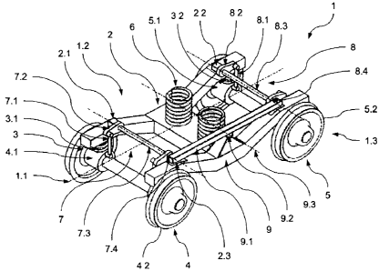
Figure 1 is a schematic perspective view of a part of a preferred embodiment
of
the vehicle 1 according to the invention having a vehicle longitudinal axis
1.1.
The vehicle 1 comprises a first vehicle component in the form of a
undercarriage frame, in this case a bogie frame 2, which is supported via a
primary suspension 3 on two wheel units in the form of sets of wheels 4 and 5.
3o The bogie frame 2, which is configured with angled end regions, extends
substantially in a plane of the bogie frame. A body (not shown in Figure 1) is
also supported on the bogie frame 2 via a secondary suspension 6.
CA 02628827 2008-05-07
-10-
The first set of wheels 4 and the second set of wheels 5 are set apart from
each other in the direction of the vehicle longitudinal axis 1.1. The bogie
frame
2 is supported on the wheel bearings of the first set of wheels 4 via a
respective
first primary spring device 3.1, whereas it is supported on the wheel bearings
of
the second set of wheels 5 via a respective second primary spring device 3.2.
In Figure 1, both the primary spring devices 3.1 and 3.2 and the secondary
suspension 6 are shown in simplified form as coil springs. However, it will be
1o understood that they can in fact also have any other desired configuration
such
as is possible for primary and secondary suspensions of this type.
A respective anti-roll device 7 or 8 is arranged between the respective set of
wheels 4, 5 and the bogie frame 2, i.e. in the region in the primary level. A
first
anti-roll device 7 is thus provided between the first set of wheels 4 and the
bogie frame 2, whereas a second anti-roll device 8 is provided between the
second set of wheels 5 and the bogie frame 2.
The first anti-roll device 7 comprises on each side of the bogie frame 2,
parallel
to each first primary spring device 3.1, a rod 7.1 which is articulated, on
the one
hand, so as to be able to pivot on the respective wheel set bearing 4.1 and,
on
the other hand, so as to be able respectively to pivot on a lever 7.2 of the
first
anti-roll device 7. The two levers 7.2 are non-rotationally located on a
torsion
shaft 7.3 of the first anti-roll device 7. The torsion shaft 7.3 is, on one
vehicle
longitudinal side 1.2, rotatably mounted in a bearing block 2.1 which is
rigidly
connected to the bogie frame 2 and forms a bearing point of the first anti-
roll
device 7 with respect to the first vehicle component 2. On the other vehicle
longitudinal side 1.3, the torsion shaft 7.3 is rotatably mounted at a first
articulation point 7.4 in a first free end of a first lever arm 9.1 of a
coupling
3o device 9, the operation of which will be described in greater detail
hereinafter.
The first articulation point 7.4 forms in this case a further bearing point of
the
first anti-roll device 7 with respect to the first vehicle component 2.
CA 02628827 2008-05-07
-11-
Similarly, the second anti-roll device 8 comprises on each side of the bogie
frame 2, parallel to each second primary spring device 3.2, a rod 8.1 which is
articulated, on the one hand, so as to be able to pivot on the respective
wheel
set bearing 5.1 and, on the other hand, so as to be able respectively to pivot
on
a lever 8.2 of the second anti-roll device 8. The two levers 8.2 are, again,
non-
rotationally located on a rotatably mounted torsion shaft 8.3 of the second
anti-
roll device 8. The torsion shaft 8.3 is, on one vehicle longitudinal side 1.2,
again
rotatably mounted in a bearing block 2.2 which is rigidly connected to the
bogie
1o frame 2 and forms a bearing point of the second anti-roll device 8 with
respect
to the first vehicle component 2. On the other vehicle longitudinal side 1.3,
the
torsion shaft 8.3 is rotatably mounted at a second articulation point 8.4 in
the
second free end of the first lever arm 9.1 of the coupling device 9, so the
first
anti-roll device 7 is mechanically coupled to the second anti-roll device 8
via the
coupling device 9. The second articulation point 8.4 forms, in this case, a
further bearing point of the second anti-roll device 8 with respect to the
first
vehicle component 2.
The term "a bearing point of the respective anti-roll device 7 or 8 with
respect to
the first vehicle components 2" refers in the sense of the present invention
to a
bearing point of the anti-roll device 7 or 8 which is stationary on non-
actuation
or fixing of the coupling device 9 and on actuation of the anti-roll device 7
or 8
with respect to the first vehicle component, i.e. in the present case the
bogie
frame 2.
The first lever arm 9.1 is articulated to the bogie frame 2 via a central
pivot
point 9.2 which is positioned in the kinematic chain centrally between the
first
articulation point 7.4 and the second articulation point 8.4. The first lever
arm
9.1 is in this case pivotable about a pivot axis 9.3 which runs parallel to
the
vehicle transverse axis and is fixed to the bogie frame 2.
CA 02628827 2008-05-07
-12-
The mode of operation of the coupling device 9 and of the first anti-roll
device 7
and second anti-roll device 8 which are coupled via said coupling device will
be
described hereinafter.
When traveling in an undeformed track bend, the body (not shown in Figure 1)
experiences, as a result of the centrifugal force acting on its center of
gravity
which is located above the bogie frame 2, a rolling moment about a roll axis
parallel to the vehicle longitudinal axis 1.1. This rolling moment results in
differingly marked resilient yielding of the secondary suspension 6. If, for
lo example, the vehicle longitudinal side 1.3 is located on the outside of the
bend,
the part of the secondary suspension 6 yields more markedly on this side than
on the other vehicle longitudinal side 1.2. This is also transmitted to the
primary
suspension 3 via the bogie frame 2. The primary springs 3.1 and 3.2 thus yield
more markedly on the bend-exterior vehicle longitudinal side 1.3 than on the
bend-interior vehicle longitudinal side 1.2. In the undeformed track bend, the
primary springs 3.1 and 3.2 yield to the same extent on the respective vehicle
longitudinal side 1.2 or 1.3.
Owing to the differingly marked resilient yielding of the primary springs 3.1
and
3.2 on the two vehicle longitudinal sides 1.3 and 1.2, the levers 7.2 of the
first
anti-roll device 7 also undergo differingly marked deflections on the two
vehicle
longitudinal sides 1.3 and 1.2. This results in resilient torsion of the
torsion shaft
7.3. The same applies to the levers 8.2 of the second anti-roll device 8 on
the
two vehicle longitudinal sides 1.3 and 1.2. These also undergo differingly
marked deflections, resulting in resilient torsion of the torsion shaft 8.3.
As, in the undeformed track bend, the forces are distributed substantially
uniformly along the vehicle longitudinal axis 1.1 and the primary springs 3.1
and 3.2 thus yield to the same extent on each vehicle longitudinal side 1.2 or
1.3, the same vertical forces act on the first articulation point 7.4 and the
second articulation point 8.4 perpendicularly to the plane of the bogie frame.
As
a result, the first lever 9.1 of the coupling device 9 remains, owing to the
central
CA 02628827 2008-05-07
-13-
arrangement of the pivot point 9.2, substantially in its neutral position
which is
shown in Figure 1 and in which it is oriented substantially parallel to the
plane
of the bogie frame. In other words, in the undeformed track bend, the two anti-
roll devices 7 and 8 provide the same effect as the known anti-roll devices in
which all of the articulation points are located in bearing blocks secured to
the
bogie frame.
The described configuration of the coupling device 9 and the articulation of
the
two anti-roll devices 7 and 8 to the coupling device 9 have, on the other
hand,
1o the effect that a counterforce-free first displacement of the anti-roll
device 7,
with a first deflection of the first articulation point 7.4 downward via the
first
lever 9.1, causes an opposing second displacement of the second anti-roll
device 8 with a second deflection, opposing the first deflection, of the
second
articulation point 8.4 upward. The amount of the displacements or deflections
is
in this case identical, whereas the directions are in each case opposite.
Such displacements of the anti-roll devices 7 and 8 produce no significant
torsion of the torsion shafts 7.3 and 8.3, so no significant additional
forces,
which would otherwise deform, in particular twist, the bogie frame 2, are
introduced into the bogie frame 2 via the anti-roll devices 7 and 8.
In order to allow displacements of the articulation points 7.4 and 8.4 in the
direction of the bogie frame, said bogie frame comprises corresponding
recesses 2.3 in the region of the free ends of the first lever 9.1.
Furthermore, it
will be understood that the mounting of the torsion shafts 7.3 and 8.3 in the
bearing blocks 2.1 and 2.2 and in the first lever 9.1 is configured in such a
way
as readily to allow tilting of the torsion shafts 7.3 and 8.3 relative to the
vehicle
transverse axis.
If, in the case of the vehicle 1 from Figure 1, the primary springs 3.1 and
3.2
therefore yield differently, not as a result of rolling of the body but rather
as a
result of deformation, for example torsion, of the section of track traveled
over,
CA 02628827 2008-05-07
-14-
i.e. as a result of differing vertical coordinates of the contact points of
the
wheels of the sets of wheels 4 and 5 on the rails (not shown in Figure 1), the
two anti-roll devices 7 and 8 can, owing to the described configuration of the
coupling device 9, if appropriate fully follow the deformed shape of the track
as
a result of tilting of the first lever 9.1. This may lead, depending on the
nature of
the deformation of the track bed, to the described displacements of the two
anti-roll devices 7 and 8 without torsion of the torsion shafts 7.3 and 8.3.
In specific cases, there is for example torsion of the track as a result of a
longitudinal gradient of the rail, which is located on the right-hand vehicle
longitudinal side 1.3 (in the direction of travel), when the rail located on
the left-
hand vehicle longitudinal side 1.2 is in the horizontal position, the two
rails
comprising the same track level in the center between the two sets of wheels 4
and 5. In this case, the contact point of the wheel 5.2, which is located at
the
front right in the direction of travel, is higher than that of the wheel
pertaining to
the same set of wheels 5 on the left-hand vehicle longitudinal side 1.2.
Conversely, the contact point of the wheel 4.2, which is located at the rear
right
in the direction of travel, is lower than that of the wheel pertaining to the
same
set of wheels 4 on the left-hand vehicle longitudinal side 1.2.
However, the vertical displacements which are transmitted via the respective
rods 7.1 and 8.1 from the front and rear wheel 4.2 and 5.2 respectively on the
right-hand vehicle longitudinal side 1.3 do not lead to torsion of the torsion
shafts 7.3 and 8.3 of the two anti-roll devices 7 and 8. On the contrary, said
displacements are compensated for by raising of the second articulation point
8.4 above the right-hand front wheel 5.2 and lowering of the first
articulation
point 7.4 above the right-hand rear wheel 4.2 via the tilting of the first
lever 9.1
about its tilt axis 9.3.
It will be understood that in the event of a differing height of the raising
or
lowering of the two wheels 4.2 and 5.2, which are arranged on the same
vehicle longitudinal side, the bogie frame 2 is raised or lowered, as a result
of
CA 02628827 2008-05-07
-15-
the residual force produced at the pivot point 9.2 in the region of the pivot
point
9.2, by half the differential amount on this vehicle longitudinal side.
Reaction
forces, such as occur in the bearings, which are rigidly connected to the
bogie
frame, of known anti-roll devices and which markedly stress the leading and
trailing ends of the longitudinal girders of the bogie frame 2, are in this
case
dispensed with.
The coupling device 9 thus brings about, in the region of the anti-roll
devices 7
and 8, advantageous isolation of reactions to rolling motions and reactions to
1o track deformations, in particular track torsion, in that mechanical
displacements
are carried out at articulation points 7.4 and 8.4 of the anti-roll devices 7
and 8.
The achievement of the described compensatory effect as a result of
mechanical displacements at articulation points 7.4 and 8.4 of the anti-roll
devices 7 and 8 has, in addition to the simple mechanical embodiment, the
advantage that the invention can be used with anti-roll devices of any desired
configuration without having in any one form substantially to intervene in the
configuration of the anti-roll device.
In order to achieve the described isolation of the reactions of the anti-roll
2o devices 7 and 8, a single coupling device 9 has merely to be provided.
Nevertheless, it will be understood that, in other variations of the
invention, a
corresponding coupling device can also be provided on both sides.
Furthermore, it will be understood that other variations of the invention can
also
make provision for a coupling device in which, on displacement of the first
anti-
roll device on the opposing vehicle longitudinal side, displacement of the
second anti-roll device in the same direction is achieved, as overall this
allows
merely the same compensatory motion to be achieved.
Second exemplary embodiment
A further advantageous embodiment of the vehicle 101 according to the
invention is shown in Figure 2. In its basic configuration and mode of
operation,
CA 02628827 2008-05-07
i
-16-
the vehicle 101 corresponds in this case to the vehicle 1 from Figure 1, so
merely the differences will now be examined.
The only difference to the embodiment from Figure 1 is the configuration of
the
coupling device 109 via which the two anti-roll devices 107 and 108 are linked
together. Instead of the first lever arm 9.1, the coupling device 109
comprises a
first lever arm 109.1 and a second lever arm 109.4 which are coupled via a
coupling rod 109.5 configured as a push/pull rod.
The first lever arm 109.1, which is configured as a short angle lever, is
articulated, in proximity to the first anti-roll device 107, to the bogie
frame 102
so as to be able to pivot about a first pivot point 109.2 having a first pivot
axis
109.3. The first pivot axis 109.3 is located in the region of the kink in the
first
lever arm 109.1 and is stationarily connected to the bogie frame 102.
The first articulation point 107.4 of the first anti-roll device 107 is
located at the
first free end of the first lever arm 109.1, whereas the coupling rod 109.5 is
articulated to the second free end of the first lever arm 109.1 via a ball-and-
socket joint or a similarly movable joint.
The second lever arm 109.4, which is also configured as a short angle lever,
is
articulated, in proximity to the second anti-roll device 108, to the bogie
frame
102 so as to be able to pivot about a second pivot point 109.6 having a second
pivot axis 109.7. The second pivot axis 109.7 is located in the region of the
kink
in the second lever arm 109.4 and is stationarily connected to the bogie frame
102.
The second articulation point 108.4 of the second anti-roll device 108 is
located
at the first free end of the second lever arm 109.4, whereas the coupling rod
109.5 is articulated to the second free end of the second lever arm 109.4 via
a
ball-and-socket joint or a similarly movable joint.
CA 02628827 2008-05-07
-17-
The first articulation point 107.4 and the second articulation point 108.4
form,
again, bearing points of the respective anti-roll device 107 or 108 with
respect
to the first vehicle component 102 in the sense of the present invention, i.e.
a
bearing point of the anti-roll device 107 or 108 which is stationary on non-
actuation or fixing of the coupling device 109 and on actuation of the anti-
roll
device 107 or 108 with respect to the first vehicle component, i.e. in this
case
the bogie frame 102.
The first lever arm 109.1 and the second lever arm 109.4 comprise identical
1o dimensions and are arranged symmetrically to the transverse center plane of
the bogie frame 102. The coupling rod 109.5 runs in this case continuously on
one side of the straight line connecting the pivot points 109.2 and 109.6, so
a
counterforce-free deflection of the first free end of the first lever arm
109.1
generates an opposing deflection of the first free end of the second lever arm
109.4 and vice versa.
Owing to the position of the first articulation point 107.4 at the first free
end of
the first lever arm 109.1 and the position of the second articulation point
108.4
at the first free end of the second lever arm 109.4, the coupling device 109,
like
the coupling device 9 from Figure 1, causes opposing deflections of the first
articulation point 107.4 and the second articulation point 108.4 of each anti-
roll
device 107 or 108. The amount of the deflections is in this case identical,
whereas the directions are opposite in each case.
The displacements resulting therefrom of the anti-roll devices 107 and 108 do
not lead to any significant torsion of the torsion shafts 107.3 and 108.3, so
no
significant additional forces, which would otherwise deform, in particular
twist,
the bogie frame 102, are introduced into the bogie frame 102 via the anti-roll
devices 107 and 108.
When traveling in an undeformed track bend, the body (not shown in Figure 2)
experiences as a result of the centrifugal force, as described hereinbefore, a
rolling moment about a roll axis parallel to the vehicle longitudinal axis
101.1.
CA 02628827 2008-05-07
-18-
This rolling moment results in differingly marked resilient yielding of the
primary
springs 103.1 and 103.2. Said springs yield more markedly on the bend-
exterior vehicle longitudinal side 101.3 than on the bend-interior vehicle
longitudinal side 101.2.
The primary springs 103.1 and 103.2 yield substantially to the same extent on
each vehicle longitudinal side 101.2 or 101.3 in the undeformed track bend
owing to the substantially uniform distribution of force. Therefore, the same
vertical forces act on the first articulation point 107.4 and the second
1o articulation point 108.4 perpendicularly to the plane of the bogie frame.
As a
result, the first lever 109.1 and the second lever 109.4 of the coupling
device
109 remain, owing to their identical dimensions, substantially in their
neutral
position shown in Figure 2. In other words, in the undeformed track bend, the
two anti-roll devices 107 and 108 also provide the same effect as the known
anti-roll devices in which all of the articulation points are located in
bearing
blocks secured to the bogie frame.
In order to allow displacements of the articulation points 107.4 and 108.4 in
the
direction of the bogie frame 102, said bogie frame comprises corresponding
2o recesses 102.3 in the region of the first free end of the first lever 109.1
and in
the region of the first free end of the second lever 109.4. Furthermore, it
will be
understood that the mounting of the torsion shafts 107.3 and 108.3 in the
bearing blocks 102.1 and 102.2 and in the first lever 109.1 and the second
lever 109.4 is configured in such a way as readily to allow tilting of the
torsion
shafts 107.3 and 108.3 relative to the vehicle transverse axis.
If, in the case of the vehicle 101 from Figure 2, the primary springs 3.1 and
3.2
yield differently, not as a result of rolling of the body but rather as a
result of
deformation, for example torsion, of the section of track traveled over, i.e.
as a
result of differing vertical coordinates of the contact points of the wheels
104.2
and 105.2 respectively of the sets of wheels 104 and 105 on the rails (not
shown in Figure 2), the two anti-roll devices 107 and 108 can, owing to the
CA 02628827 2008-05-07
-19-
described configuration of the coupling device 109, if appropriate fully
follow the
deformed shape of the track as a result of tilting of the first lever 109.1
and the
second lever 109.4. This may lead, depending on the nature of the deformation
of the track bed, to the described displacements of the two anti-roll devices
107
and 108 without torsion of the torsion shafts 107.3 and 108.3.
It will be understood that in the event of a differing height of the raising
or
lowering of the two wheels 104.2 and 105.2, which are arranged on the same
vehicle longitudinal side, the bogie frame 102 is centrally raised or lowered,
as
1o a result of the residual force produced in the coupling device 109 at the
pivot
points 109.2 and 109.6, by half the differential amount on this vehicle
longitudinal side. Reaction forces, such as occur in the bearings, which are
rigidly connected to the bogie frame, of known anti-roll devices and which
markedly stress the leading and trailing ends of the longitudinal girders of
the
bogie frame 102, are in this case dispensed with.
The coupling device 109 thus brings about, in the region of the anti-roll
devices
107 and 108, likewise advantageous isolation of reactions to rolling motions
and reactions to track deformations, in particular track torsion, in that
mechanical displacements are carried out at articulation points 107.4 and
108.4
of the anti-roll devices 107 and 108. The advantages of this isolation have
been
discussed hereinbefore in relation to Figure 1, so reference is made in this
regard to the foregoing discussion.
Third exemplary embodiment
A further advantageous embodiment of the vehicle 201 according to the
invention with the isolation in the region of the secondary suspension is
shown
in Figure 3. Figure 3 is a schematic perspective view of a part of the vehicle
3o 201 having a vehicle longitudinal axis 201.1. The vehicle 201 comprises a
first
vehicle component in the form of a body 202 which is respectively supported
via a body spring device (not shown), for example a secondary spring device,
CA 02628827 2008-05-07
-20-
on two wheel units, in the form of running gears 204 and 205, which are set
apart from each other in the direction of the vehicle longitudinal axis 201.1.
It will be understood that the undercarriages 204 and 205 can be
undercarriages of any desired configuration. They may, for example, be both
single-axle undercarriages and bogies. In the case of single-axle running
gears,
in particular, the body spring device can then be configured at one level and
form the sole suspension of the body.
1 o A respective anti-roll device 207 or 208 is arranged between the
respective
undercarriage 204, 205 and the body 202, i.e. in the region in the body
suspension level, parallel to the body spring devices contained therein. A
first
anti-roll device 207 is thus provided between the first undercarriage 204 and
the body 202, whereas a second anti-roll device 208 is provided between the
second undercarriage 205 and the body 202.
The first anti-roll device 207 comprises on each side of the first
undercarriage
204, parallel to each body spring device, a rod 207.1 which is pivotably
articulated, on the one hand, to a lever 207.2 of the first anti-roll device
207.
2o The two levers 207.2 are non-rotationally located on a torsion shaft 207.3
of the
first anti-roll device 207. The torsion shaft 207.3 is, on both vehicle
longitudinal
sides 201.2 and 201.3, rotatably mounted in a bearing block 202.1 which is
rigidly connected to the first undercarriage 204. On one vehicle longitudinal
side 201.2, the lever 207.2 is pivotably articulated to the body 202. On the
other
vehicle longitudinal side 201.3, the lever 207.2 is rotatably mounted at a
first
articulation point 207.4 in a first free end of a first lever arm 209.1 of a
coupling
device 209, the operation of which will be described in greater detail
hereinafter.
Similarly, the second anti-roll device 208 comprises on each side of the
second
undercarriage 205, parallel to each body spring device, a rod 208.1 which is
pivotably articulated, on the one hand, to a lever 208.2 of the second anti-
roll
device 208. The two levers 208.2 are non-rotationally located on a torsion
shaft
CA 02628827 2008-05-07
-21 -
208.3 of the second anti-roll device 208. The torsion shaft 208.3 is, on both
vehicle longitudinal sides 201.2 and 201.3, rotatably mounted in a bearing
block 202.2 which is rigidly connected to the second undercarriage 205. On
one vehicle longitudinal side 201.2, the lever 208.2 is pivotably articulated
to
the body 202. On the other vehicle longitudinal side 201.3, the lever 207.2 is
rotatably mounted at a second articulation point 208.4 in a first free end of
a
second lever arm 209.4 of the coupling device 209. The first lever arm 209.1
and the second lever arm 209.4 are mechanically connected via a coupling rod
209.5, so the first anti-roll device 207 is mechanically coupled to the second
lo anti-roll device 208 via the coupling device 209.
The first lever arm 209.1, which is configured as a short angle lever, is
articulated, in proximity to the first anti-roll device 207, to the body 202
so as to
be able to pivot about a first pivot point 209.2 having a first pivot axis
209.3.
The first pivot axis 209.3 is located in the region of the kink in the first
lever arm
209.1 and is stationarily connected to the body 202.
The first articulation point 207.4 of the first anti-roll device 207 is
located at the
first free end of the first lever arm 209.1, whereas the coupling rod 209.5 is
2o articulated to the second free end of the first lever arm 209.1.
The second lever arm 209.4, which is also configured as a short angle lever,
is
articulated, in proximity to the second anti-roll device 208, to the body 202
so
as to be able to pivot about a second pivot point 209.6 having a second pivot
axis 209.7. The second pivot axis 209.7 is located in the region of the kink
in
the second lever arm 209.4 and is stationarily connected to the body 202.
The second articulation point 208.4 of the second anti-roll device 208 is
located
at the first free end of the second lever arm 209.4, whereas the coupling rod
209.5 is articulated to the second free end of the second lever arm 209.4.
CA 02628827 2008-05-07
-22-
The first articulation point 207.4 and the second articulation point 208.4
form,
again, bearing points of the respective anti-roll device 207 or 208 with
respect
to the first vehicle component 202 in the sense of the present invention, i.e.
a
bearing point of the anti-roll device 207 or 208 that is stationary on non-
actuation or fixing of the coupling device 209 and on actuation of the anti-
roll
device 207 or 208 with respect to the first vehicle component, i.e. in this
case
the body 202.
The first lever arm 209.1 and the second lever arm 209.4 comprise identical
1o dimensions and are arranged symmetrically to the transverse center plane of
the body 202. The coupling rod 209.5 runs in this case continuously on one
side of the straight line connecting the pivot points 209.2 and 209.6, so a
counterforce-free deflection of the first free end of the first lever arm
209.1
generates an opposing deflection of the first free end of the second lever arm
209.4 and vice versa.
Owing to the position of the first articulation point 207.4 at the first free
end of
the first lever arm 209.1 and the position of the second articulation point
208.4
at the first free end of the second lever arm 209.4, the coupling device 209,
like
the coupling device 109 from Figure 2, causes opposing deflections of the
first
articulation point 207.4 and the second articulation point 208.4 of each anti-
roll
device 207 or 208. The amount of the deflections is in this case identical,
whereas the directions are opposite in each case.
The mode of operation of the coupling device 209 and of the first anti-roll
device 207 and second anti-roll device 208 which are coupled via said coupling
device will be described hereinafter.
When traveling in an undeformed track bend, the body 202 experiences, as a
3o result of the centrifugal force acting on its center of gravity which is
located
above the undercarriage, a rolling moment about a roll axis parallel to the
vehicle longitudinal axis 201.1. This rolling moment results in differingly
marked
CA 02628827 2008-05-07
-23-
resilient yielding of the secondary suspension. If, for example, the vehicle
longitudinal side 201.3 is located on the outside of the bend, the part of the
body suspension devices yields more markedly on this side than on the other
vehicle longitudinal side 201.2. In the undeformed track bend, the body spring
devices yield to the same extent on the respective vehicle longitudinal side
201.2 or 201.3.
In the event of differingly marked resilient yielding of the body spring
devices on
the two vehicle longitudinal sides 201.3 and 201.2, the levers 207.2 of the
first
1o anti-roll device 207 also undergo differingly marked deflections on the two
vehicle longitudinal sides 201.3 and 201.2. This results in resilient torsion
of the
torsion shaft 207.3. The same applies to the levers 208.2 of the second anti-
roll
device 208 on the two vehicle longitudinal sides 201.3 and 201.2. These also
undergo differingly marked deflections, resulting in resilient torsion of the
torsion shaft 208.3.
As, in the undeformed track bend, the forces are distributed substantially
uniformly along the vehicle longitudinal axis 201.1 and the body spring
devices
thus yield to the same extent on each vehicle longitudinal side 201.2 or
201.3,
the same vertical forces act on the first articulation point 207.4 and the
second
articulation point 208.4 perpendicularly to the plane of the undercarriage. As
a
result, the first lever 209.1 and the second lever 209.4 of the coupling
device
209 remain substantially in their neutral position shown in Figure 3. In other
words, in the undeformed track bend, the two anti-roll devices 207 and 208
provide the same effect as the known anti-roll devices in which all of the
articulation points of the two anti-roll devices are located in bearing blocks
secured to the body, as is indicated in Figure 3 by the broken contours 210.1
on the vehicle longitudinal side 201.3.
The described configuration of the coupling device 209 and the articulation of
the two anti-roll devices 207 and 208 to the coupling device 209 have, on the
other hand, the effect that a counterforce-free first displacement of the
first anti-
roll device 207, with a first deflection of the first articulation point 207.4
CA 02628827 2008-05-07
-24-
downward via the coupling device 209, causes an opposing second
displacement of the second anti-roll device 208 with a second deflection,
opposing the first deflection, of the second articulation point 208.4 upward.
Such displacements of the anti-roll devices 207 and 208 produce no significant
torsion of the torsion shafts 207.3 and 208.3, so no significant additional
forces,
which would otherwise deform, in particular twist, the body 202, are
introduced
into the body 202 via the anti-roll devices 207 and 208.
1o If, in the case of the vehicle 201 from Figure 3, the body spring devices
yield
differently, not as a result of rolling of the body 202 but rather as a result
of
deformation, for example torsion, of the section of track traveled over, i.e.
as a
result of differing vertical coordinates of the contact points of the wheels
of the
undercarriages 204, 205 on the rails (not shown in Figure 3), the two anti-
roll
devices 207 and 208 can, owing to the described configuration of the coupling
device 209, if appropriate fully follow the deformed shape of the track as a
result of synchronous tilting of the first lever 209.1 and the second lever
209.4.
This may lead, depending on the nature of the deformation of the track bed, to
the described displacements of the two anti-roll devices 207 and 208 without
torsion of the torsion shafts 207.3 and 208.3.
In specific cases, there is for example torsion of the track as a result of a
longitudinal gradient of the rail, which is located on the right-hand vehicle
longitudinal side 201.3 (in the direction of travel), when the rail located on
the
left-hand vehicle longitudinal side 201.2 is in the horizontal position, the
two
rails comprising the same track level in the center between the two
undercarriages 204, 205. In this case, the contact point of the wheel which is
located at the front right in the direction of travel is higher than that of
the wheel
pertaining to the same undercarriage on the left-hand vehicle longitudinal
side
201.2. Conversely, the contact point of the wheel which is located at the rear
right in the direction of travel is lower than that of the wheel pertaining to
the
same undercarriage on the left-hand vehicle longitudinal side 201.2. Similar
CA 02628827 2008-05-07
-25-
states of the track bed may result when traveling in sections of differing
track
superelevation.
However, the vertical displacements which are transmitted via the respective
rods 207.1 and 208.1 from the front and rear wheel on the right-hand vehicle
longitudinal side 201.3 do not lead to torsion of the torsion shafts 207.3 and
208.3 of the two anti-roll devices 207 and 208. On the contrary, said
displacements are compensated for by raising of the second articulation point
208.4 above the right-hand front wheel and lowering of the first articulation
point 207.4 above the right-hand rear wheel via the synchronous tilting of the
first lever 209.1 and the second lever 209.4 about its tilt axis 209.3 and
209.7
respectively.
It will be understood that in the event of a differing height of the raising
or
lowering of the two wheels 204.2 and 205.2, which are arranged on the same
vehicle longitudinal side, the body 202 is raised or lowered, as a result of
the
residual force produced on the coupling device 209.2 in the central region, by
half the differential amount on this vehicle longitudinal side. Reaction
forces,
such as occur in the bearings, which are rigidly connected to the body, of
known anti-roll devices and which markedly stress the body 202, are in this
case dispensed with.
The coupling device 209 thus brings about, in the region of the anti-roll
devices
207 and 208, advantageous isolation of reactions to rolling motions and
reactions to track deformations, in particular track torsion, in that
mechanical
displacements are carried out at articulation points 207.4 and 208.4 of the
anti-
roll devices 207 and 208. The achievement of the described compensatory
effect as a result of mechanical displacements at articulation points 207.4
and
208.4 of the anti-roll devices 207 and 208 has, in addition to the simple
mechanical embodiment, the advantage that the invention can be used with
anti-roll devices of any desired configuration without having in any one form
substantially to intervene in the configuration of the anti-roll device.
CA 02628827 2008-05-07
-26-
As is indicated in Figure 3 by the contour 210.2, one or more adjusting and/or
damping devices can be provided in the region of the coupling device 209 in
order to generate active adjusting forces and/or to damp the motions occurring
in the arrangement. The adjusting and/or damping device 210.2 can thus, for
example, be used actively to generate a desired rolling motion of the body 202
by varying the length of the coupling rod 209.5.
It will be understood in this regard that adjusting and/or damping devices of
this
lo type can, in other variations of the vehicle according to the invention,
also be
arranged at a different location. It will also be understood that adjusting
and/or
damping devices of this type can be used also in all of the other exemplary
embodiments described in the present document.
In order to achieve the described isolation of the reactions of the anti-roll
devices 207 and 208, a single coupling device 209 has merely to be provided.
Nevertheless, it will be understood that, in other variations of the
invention, a
corresponding coupling device can also be provided on both sides.
Furthermore, it will be understood that other variations of the invention can
also
make provision for a coupling device in which, on displacement of the first
anti-
roll device on the opposing vehicle longitudinal side, displacement of the
second anti-roll device in the same direction is achieved, as overall this
allows
merely the same compensatory motion to be achieved.
Fourth exemplary embodiment
The exemplary embodiments described hereinbefore related to applications
within a undercarriage or within a carriage as a first vehicle component, in
which excessive torsional loads resulting from winding sections of track are
intended to be avoided within the respective structure of the vehicle
component. A comparable task must be performed for articulated trains, such
as for example multiple-unit trams or trains, which consist of individual
CA 02628827 2008-05-07
-27-
segments which are coupled to one another and have crossings for passengers
located therebetween. This applies, in particular, when individual segments
are
not supported on their own undercarriages but rather are connected to their
neighboring segments as what are known as "sedans" via articulated links in
the floor region and are optionally further coupling elements in the roof
region.
The invention can advantageously be applied in this case too. Figures 4 and 5
are schematic plan views onto a part of a vehicle 301 according to the
invention
having a vehicle longitudinal axis 301.1. The vehicle 301 comprises a first
1o vehicle component in the form of a wheelless first body 302 which is
supported
on two adjacent second vehicle components in the form of a second body 311
and a third body 312 in the manner of a sedan of this type.
The bodies 311 and 312 are each supported on running gears 304 and 305 via
corresponding spring devices in the region adjoining the first body 302. The
first
body 302 is thus supported on the first undercarriage 304 via the second body
311 and the associated spring device and on the second undercarriage 305 via
the third body 312 and the associated spring device. In other words, the
bodies
302, 311 and 312 are thus vehicle segments of the multiple-unit vehicle 301.
Whereas excessive rolling differences between the bodies 302, 311 and 312
are intended to be prevented, staggered inclinations of the successive bodies
302, 311 and 312 about their respective longitudinal axis that are produced as
a result of traveling on the deformed sections of track described in detail
hereinbefore, in particular winding sections of track, are intended to be
allowed.
Known solutions comprise, for example, rods which are arranged in the roof
region between adjacent bodies in the transverse direction and connect said
bodies in an articulated manner, such as are indicated by the broken contours
3o 310 in Figure 4. The bodies 302, 311, 312 are furthermore articulated to
one
another, for example, by an articulation (not shown) in the floor region. In
the
event of rolling motions of a body 302, 311, 312, i.e. a transverse motion in
the
CA 02628827 2008-05-07
-28-
roof region relative to the lower rolling pole, this transverse motion is
transmitted to the adjacent body of the articulated train via the rigidity of
the
rods 310. The rods 310 thus prevent the bodies 302, 311, 312 from rolling
relative to one another while at the same time allowing relative pitching of
the
bodies 302, 311, 312 such as can occur when traveling on track troughs or
crests.
However, when traveling on winding sections of track, these rods 310 attempt
to hold the adjacent bodies 302, 311, 312 all parallel to one another, in
particular parallel to one another in the vertical direction, leading to the
production of marked restraining forces at the articulation points of these
rods
310 and thus of the structure of the bodies 302, 311, 312.
Isolation according to the invention of the dynamically conditioned and
undesirable rolling motion of the relative transverse inclination, generated
by
traveling over a deformed section of track, for example a winding section of
track, of successive segments of an articulated train is required to overcome
this drawback.
In the case of the vehicle 301 illustrated schematically in Figures 4 and 5,
this
is achieved as follows, Figure 4 being a plan view of the situation on a flat
track
and Figure 5 showing the situation on a winding track:
A respective anti-roll device 307 or 308 is arranged between the respective
second body 311, 312 and the first body 302. A first anti-roll device 307 is
thus
provided between the body 311 and the body 302, whereas a second anti-roll
device 308 is provided between the body 312 and the body 302.
The first anti-roll device is configured in the form of a first push/pull rod
307
which is pivotably articulated, on the one hand, to a bracket on the second
body 311. At its end facing the first body 302, the first rod 307 is rotatably
mounted at a first articulation point 307.4 in a first free end of a first
lever arm
CA 02628827 2008-05-07
-29-
309.1 of a coupling device 309, the operation of which will be described
hereinafter in greater detail.
Similarly, the second anti-roll device 308 is configured in the form of a
second
push/pull rod 308 which is pivotably articulated, on the one hand, to a
bracket
on the third body 312. At its end facing the first body 302, the second rod
308 is
rotatably mounted at a second articulation point 308.4 in a first free end of
a
second lever arm 309.4 of the coupling device 309. The first lever arm 309.1
and the second lever arm 309.4 are mechanically connected via a coupling rod
1o 309.5, so the first anti-roll device 307 is mechanically coupled to the
second
anti-roll device 308 via the coupling device 309.
The first lever arm 309.1, which is configured as a short angle lever, is
articulated, in proximity to the first anti-roll device 307, to the first body
302 so
as to be able to pivot about a first pivot point 309.2 having a first pivot
axis. The
first pivot axis is located in the region of the kink in the first lever arm
309.1 and
is stationarily connected to the first body 302.
The first articulation point 307.4 of the first anti-roll device 307 is
located at the
first free end of the first lever arm 309.1, whereas the coupling rod 309.5 is
articulated to the second free end of the first lever arm 309.1.
The second lever arm 309.4, which is also configured as a short angle lever,
is
articulated, in proximity to the second anti-roll device 308, to the first
body 302
so as to be able to pivot about a second pivot point 309.6 having a second
pivot axis. The second pivot axis 309.7 is located in the region of the kink
in the
second lever arm 309.4 and is stationarily connected to the body 302.
The second articulation point 308.4 of the second anti-roll device 308 is
located
3o at the first free end of the second lever arm 309.4, whereas the coupling
rod
309.5 is articulated to the second free end of the second lever arm 309.4.
CA 02628827 2008-05-07
-30-
The first articulation point 307.4 and the second articulation point 308.4
form,
again, bearing points of the respective anti-roll device 307 or 308 with
respect
to the first vehicle component 302 in the sense of the present invention, i.e.
a
bearing point of the anti-roll device 307 or 308 which is stationary on non-
actuation or fixing of the coupling device 309 and on actuation of the anti-
roll
device 307 or 308 with respect to the first vehicle component, i.e. in this
case
the first body 302.
The first lever arm 309.1 and the second lever arm 309.4 comprise identical
1o dimensions and are arranged symmetrically to the transverse center plane of
the first body 302. The coupling rod 309.5 runs in this case continuously on
one
side of the straight line connecting the pivot points 309.2 and 309.6, so a
counterforce-free deflection of the first free end of the first lever arm
309.1
generates an opposing deflection of the first free end of the second lever arm
309.4 and vice versa.
Owing to the position of the first articulation point 307.4 at the first free
end of
the first lever arm 309.1 and the position of the second articulation point
308.4
at the first free end of the second lever arm 309.4, the coupling device 309,
like
the coupling device 109 from Figure 2, causes opposing deflections of the
first
articulation point 307.4 and the second articulation point 308.4 of each anti-
roll
device 307 or 308. The amount of the deflections is in this case identical,
whereas the directions are opposite in each case.
The mode of operation of the coupling device 309 and of the first anti-roll
device 307 and second anti-roll device 308 which are coupled via said coupling
device will be described hereinafter.
If the first body 302 experiences, for example as a result of uneven running
and
its high center of gravity, a pure rolling moment about a roll axis parallel
to the
vehicle longitudinal axis 301.1, the first articulation point 307.4 and the
second
articulation point 308.4 at its two body ends move with respect to the
adjacent
CA 02628827 2008-05-07
-31-
bodies 311, 312 in the same relative direction. The first free ends of the two
angle levers 309.1 and 309.4 are thus symmetrically loaded, i.e. a force of
substantially the same direction and the same amount is exerted thereon. Their
inherent rigidity and the rigidity of the coupling rod 309.5 prevent the angle
levers 309.1 and 309.4 from rotating so the arrangement, like the known rods
310, counteracts the rolling motion.
On winding of the track, the bodies 302, 311, 312, etc. in the direction of
travel
are successively deflected out of the vertical direction. The relative
horizontal
1o motion between the first body 302 and the preceding third body 312 and
between the first body 302 and the subsequent second body 311 is then
carried out in the opposite direction. This allows the two angle levers 309.1
and
309.4 to rotate in the same direction about their respective pivot point 309.2
or
309.6. The coupling rod 309.5 does not in this case experience any significant
force but rather also moves almost without resistance in the vehicle
longitudinal
direction 301.1. As a result, the brackets on the bodies 302, 311, 312, like
the
bodies 302, 311, 312 themselves, are not loaded with constraining forces as in
the conventional case with the rods 310.
In a mixed form of both motions, i.e. in the event of simultaneous rolling of
one
body when traveling over a section of deformed track, only those differential
forces which correspond to the actual rolling of a single body relative to the
bodies adjacent thereto are accommodated by the brackets of the anti-roll
devices 307, 308, whereas the increasing oblique position, caused by the
winding of the track, of the bodies 302, 311, 312 does not produce any
undesirable constraining forces in the transverse direction.
Fifth exemplary embodiment
A further advantageous embodiment of the vehicle 401 according to the
invention comprising the bodies 402, 411, 412 is shown in Figure 6. In its
basic
CA 02628827 2008-05-07
-32-
configuration and mode of operation, the vehicle 401 corresponds in this case
to the vehicle 301 from Figure 4, so merely the differences will now be
examined.
The only difference to the embodiment from Figure 4 is the configuration of
the
coupling device 409 via which the two anti-roll devices 407 and 408 are linked
together. Instead of the coupling rod 309.5, the coupling device 409 comprises
a hydraulic coupling 409.5 having hydraulic cylinders 409.8 and 409.9, the
working chambers of which are connected via a hydraulic line 409.10.
The hydraulic cylinders 409.8 and 409.9 are each pivotably articulated at one
end to the first body 402. At its other end, the first hydraulic cylinder
409.8 is
pivotably articulated to the first lever arm 409.1, whereas the second
hydraulic
cylinder 409.9 is pivotably articulated to the second lever arm 409.4.
It will be understood that, in other variations of the vehicle according to
the
invention, the hydraulic coupling device described hereinbefore can also be
provided with an active adjusting device and/or a damping device. There may
thus be provided, for example, a corresponding pump and control unit or the
like which modifies the filling level of the working chambers of the hydraulic
cylinders as instructed by a control device.
It will be understood that, in other variations of the vehicle according to
the
invention, the coupling mechanisms described hereinbefore, or else other
coupling mechanisms, can be used individually or in combination in order to
provide the coupling according to the invention between the anti-roll devices.
The present invention has been described hereinbefore exclusively based on
examples of rail vehicles. Finally, it will furthermore be understood that the
invention can also be used in conjunction with any other desired vehicles.