Note: Descriptions are shown in the official language in which they were submitted.
CA 02629320 2008-05-09
WO 2007/120261
PCT/US2006/060713
EXPEDITED DIGITAL SIGNAL DECODING
FIELD OF THE INVENTION
This invention relates in general to broadband communications systems, and
more
particularly, to the use of a decoder buffer and particular data rates to
perform an expedited
channel alteration.
BACKGROUND
A broadband communications system includes data sources, a broadcasting
network, a headend unit, and edge devices. The data sources can be encoders
and video
sources that send data through an uplink to the broadcasting network. In the
broadcasting
network, three common types of signals received at the headend include off-air
signals,
satellite signals, and local origination signals. The satellite signals
include any signal
transmitted from an earth station to an orbiting satellite which are then
retransmitted back
down to earth. The signals are transmitted from earth to the orbiting
satellite on a path
referred to as the uplink. These signals are then received by a transponder on
the satellite
and are retransmitted from the transponder to a receiving earth station over a
downlink.
The transponder amplifies the incoming signal and changes its frequency for
the
downlink journey to avoid interference with uplink signals.
The headend (HE) or central office is where signals from multiple sources are
received and are conditioned and prepared for transmission over an access
network to
subscribers. Once signals have been prepared for delivery, they are combined
onto a
medium to be sent over the access network to the customer premise devices.
Conditioning may include conversion of analog to digital, digital bit-rate
conversion,
CA 02629320 2008-05-09
WO 2007/120261
PCT/US2006/060713
conversion from variable bit rate to constant or clamped bit rate, conversion
of multiple-
program transport streams to single-program transport streams or any other
type of
grooming or combination of these. The medium may include coaxial, twisted pair
or
other cable, optical fiber, or some form of wireless transmission. The
preparation for
transmission in edge devices may include generation of an RF carrier,
modulation,
conversion to optical, frequency division multiplexing, time division
multiplexing,
wavelength division multiplexing or any combination of these.
Edge devices vary depending on the type of network, and include the headend
output devices. These edge devices sometime overlap with or extend into an
access
o network. The fiber access network can include an optical line terminal
(OLT), an optical
node terminal (ONT), and customer premises devices inside the home. Therefore,
the
OLT and ONT may be considered either an edge device or an access network
device.
However, the ONT may at times be considered a customer premises device.
A hybrid fiber/coax (HFC) network typically uses modulator edge devices. An
HFC access network can include RF to optical converters, optical to RF
converters,
optical and RF amplifiers, optical and RF combiners, splitters and taps. HFC
customer
premises devices include RF modems and set-top boxes.
A digital subscriber line (DSL) network can include a digital subscriber line
access multiplexer (DSLAM). DSL modems are usually located in customer
premises.
The OLTs, modulators, and DSLAMs, also known as edge devices, service numerous
user homes, such as a neighborhood in a city. Customer premise devices can
include
modems, routers, personal computers, set-top boxes (STB), etc.
FIG. 1 illustrates a satellite broadcast network 100. At an uplink facility
110,
program content is stored on video servers controlled by a broadcast
automation system.
Any analog content at a network operations center (NOC) 120 is compressed
using encoders
2
CA 02629320 2008-05-09
WO 2007/120261
PCT/US2006/060713
and then multiplexed with the content delivered from the video file servers.
The NOC 120 is
responsible for overall control and co-ordination of the uplink and the
downlink sites. A
headend (HE) 130 may include a network groomer 140 for generating multicast
data
streams such as video, audio, and/or data signals. The headend 130 also has
numerous
decoders which preferably each have a mass storage device, such as a hard disk
drive.
The standard encoding technique proposed by the Moving Pictures Experts Group
(MPEG) uses a variable length coding method. Accordingly, the amount of the
data
output from an encoder of a transmitter varies according to a change in a
scene or the
magnitude of motion in an image input from an external information source.
Therefore, it
is required that the occupancy level of a buffer in a set-top box, which
stores a received
signal, is appropriately controlled.
Problems occur when tuning to a digital channel because the MPEG buffer must
fill before starting to decode and display images. This can take up to two
seconds and
negatively impacts channel change times. If playback begins before the buffer
is full,
underflow may result. What is needed is a means to facilitate fast channel
change before
the buffer is full.
3
CA 02629320 2008-05-09
WO 2007/120261
PCT/US2006/060713
BRIEF DESCRIPTION OF THE DRAWINGS
The invention can be better understood with reference to the following
drawings.
The components in the drawings are not necessarily drawn to scale, emphasis
instead being
placed upon clearly illustrating the principles of the invention. In the
drawings, like
reference numerals designate corresponding parts throughout the several views.
FIG. 1 illustrates a satellite broadcast system with an uplink, headend, and
network operations center.
FIG. 2 illustrates the system of FIG. 1 in combination with a fiber access
network
and a customer premises network.
FIG. 3 illustrates the system of FIG. 1 in combination with a hybrid
fiber/coax
access network and a customer premises network.
FIG. 4 illustrates the system of FIG. 1 in combination with a DSL access
network
and a customer premises network.
FIG. 5 illustrates multicast data flow from a headend to a set-top box.
FIG. 6 illustrates a unicast data flow from a headend to a set-top box.
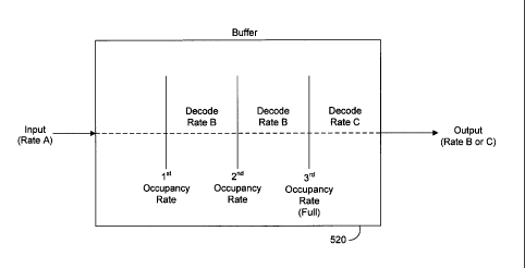
FIG. 7 illustrates buffer occupancy levels and corresponding data flow rates.
4
CA 02629320 2012-04-11
DETAILED DESCRIPTION
The embodiments of the invention can be understood in the context of a
broadband communications system. Note, however, that the invention may be
embodied
in many different forms and should not be construed as limited to the
embodiments set
forth herein. For example, transmitted broadband signals may include at least
one of
video/audio, telephony, data, or Internet Protocol (IP) signals, to name but a
few. All
examples given herein, therefore, are intended to be non-limiting and are
provided in
order to help clarify the description of the invention.
Set-top boxes tune to data streams coming from the HE 130 in a broadcast
network which could be composed of fiber, hybrid fiber/coax, or xDSL. These
broadcast
networks are described in U.S. patent 7,742,407, entitled "Quality of Service
Management in a Switched Digital Video Environment", U.S. patent 8,099,756,
entitled
"Channel Changes Between Services with Differing Bandwidth in a Switched
digital
Video system", U.S. patent application 2007-0107024, entitled "Atomic Channel
Changes in a Switched Digital Video System", and U.S. patent application 2007-
0106782, entitled "Bandwidth Management in Each Network Device in a Switched
Digital Video Environment", all filed November 10, 2005.
An MPEG buffer, or decoder buffer, in the set-top box must completely fill
with
the incoming data stream before starting to decode and display images or
underflow will
occur. The incoming data stream can be in numerous formats, such as MPEG2,
MPEG4,
VC1, audio formats, or any other format known to those skilled in the art.
FIG. 2 illustrates the satellite broadcast system 100 of FIG. 1 in combination
with a fiber access network 200 and a customer premises network 280. Encoders
210 and
video servers 220 are the data sources that feed a broadcast network 230 of
the satellite
CA 02629320 2008-05-09
WO 2007/120261
PCT/US2006/060713
broadcast system 100. Video servers 240 and encoders 250 located at the HE 130
are
used to insert local programming. The HE 130 of the satellite broadcast system
100
receives signals from multiple sources, conditions them and prepares them for
transmission over the access network 200. Once signals have been prepared for
transmission from the HE 130, they are combined onto the access network media.
In a
fiber access network 200 an optical line terminal (OLT) 260 transmits
downstream to
optical network terminals (ONT) 270 which are located outside the customer
premises
network 280. The OLT 260 is responsible for allocating necessary upstream
bandwidths
to the ONTs 270 by issuing data grants in an appropriate manner. Inside the
customer
premises network 280, the signals can be split and combined using a router
282, or other
device, and then fed to various devices, such as one or more set-top boxes
(STBs) 284 or
personal computers (PCs) 286.
FIG. 3 illustrates the satellite broadcast system 100 of FIG. 1 in combination
with
a hybrid fiber/coax (HFC) access network 300 and the customer premises network
280.
The components used for the HFC access network 300 are similar to those used
for the
fiber access network 200. However, instead of the OLT 260 and the ONT 270, the
hybrid
fiber/coax network 300 uses an edge modulator 310. Inside the customer
premises
network 280, the signal is received by a cable modem 320 and sent to various
devices,
such as one or more STBs, also known as home communication terminals, 284 or
PCs
286. RF STBs may interface to the HFC access network 300 directly using
internal
modems.
FIG. 4 illustrates the satellite broadcast system 100 of FIG. 1 in combination
with
a DSL access network 400 and the customer premises network 280. The components
used for the DSL access network 400 are similar to those used in the fiber
access network
200 and the HFC access network 300 except for the edge devices. Instead of the
OLT
6
CA 02629320 2008-05-09
WO 2007/120261
PCT/US2006/060713
260 and the ONT 270 or the modulator 310, the DSL access network 400 has a
digital
subscriber line access multiplexer (DSLAM) 410 that links numerous users to a
single
high-speed ATM line. Inside the customer premises network 280, the signal is
received
by a local network 420 possibly containing a modem and bridge router. The
signal is
split there and fed to various devices, such as one or more STBs 284 or PCs
286.
FIG. 5 illustrates multicast data flow, which is the simultaneous delivery of
information to a group of devices, from the HE 130. The STB 284 requests a
signal and
the HE 130 sends the multicast data flow over an edge device 510 to the STB
284. The
STB 284 tunes to the multicast video stream and a decoder/dejitter buffer 520
in the STB
284 fills with packets directly from the multicast video stream. The data
stream is
typically entering the buffer 520 at a natural stream rate. However, when a
key frame,
such as an I frame, is received and the buffer 520 is partially full, the
decoder may start to
output the data at a rate lower than the natural stream rate. This allows the
buffer to
continue filling while images are displayed to the user. Because data is
output from the
buffer 520 before the buffer is full, the user experiences faster channel
changes or
alterations without experiencing buffer underflow.
Once the buffer 520 is full, the output rate will increase to the natural
stream rate.
For example, if a video stream is entering the buffer 520 at a natural stream
rate of three
megabytes per second, the output rate from the decoder will be less, such as
2.5
megabytes per second. This gives the buffer 520 time to fill completely, but
also allows
the user to receive the requested data before the buffer 520 is full. Once the
buffer 520 is
completely full, the output rate from the decoder will increase to the natural
stream rate
which in this case is three megabytes per second.
FIG. 6 illustrates a unicast data flow, which is a single stream of data, from
the
HE 130 to the STB 284. This unicast flow may be a flow destined only to this
STB 284,
7
CA 02629320 2008-05-09
WO 2007/120261
PCT/US2006/060713
for instance VOD. This unicast flow may also be a flow associated with quickly
filling
buffer 520 prior to tuning to a multicast flow. The STB 284 requests a signal
and the HE
130 sends out the unicast data flow over the edge device 510. The STB 284
tunes to the
unicast video stream, and the decoder buffer 520 in the STB 284 fills with
packets
directly from the unicast video stream. Because the input into the buffer 520
of FIG. 6 is
a unicast data flow, the input rate into the STB 284 may be faster than or
equal to the
natural rate. When a key frame, such as an I frame, is received and the buffer
520 is
partially full, the decoder may start to output the data at a rate lower than
the natural
stream rate. After a period of time or a set buffer occupancy level, the STB
284 may
switch from the unicast data flow to a multicast data flow. The buffer 520
will continue
to fill and, once full, the decoder will then decode at the natural stream
rate.
FIG. 7 illustrates buffer occupancy levels and corresponding data flow rates.
For
purposes of this illustration, buffer occupancy increases from the left side
of the buffer
520 to the right side of the buffer 520. Therefore, the varying output data
flow from the
buffer 520 is illustrated in conjunction with the varying occupancy level of
the buffer
520. The data stream, whether a multicast or unicast stream, is input to the
buffer 520 at
a natural stream rate or a rate faster than the natural stream rate, for
example Rate A.
When a first occupancy level is reached in the buffer, the decoder begins
decoding the
data and outputting the data at a rate lower than the natural stream rate,
such as Rate B.
At a second occupancy level, the data stream could change from a unicast
stream to a
multicast stream, remain a unicast stream, or remain a multicast stream. When
the buffer
520 has filled, the decoded data output rate increases from Rate B to Rate C.
Rate C
could be equal to Rate A or the natural stream rate.
For example, the STB 284 can request a unicast data stream from the HE 130.
The unicast data stream is sent at Rate A, a natural data rate of six
megabytes per second,
8
CA 02629320 2008-05-09
WO 2007/120261 PCT/US2006/060713
to the buffer 520 in the STB 284. Once the buffer 520 has begun to fill and
reached a key
frame, a first occupancy level has been reached. The buffer 520 begins to
output data to
the decoder at Rate B, which is four megabytes per second. When the buffer 520
has
reached a second occupancy level, the STB 284 requests that the data flow from
the HE
130 become a multicast data flow, which allows more information to be sent
from the HE
130 to the STB 284. Once the buffer 520 is substantially full, a third
occupancy level has
been reached. The data output rate is increased to Rate C, which is equal to
Rate A, the
natural data rate.
It should be emphasized that the above-described embodiments of the invention
are merely possible examples, among others, of the implementations, setting
forth a clear
understanding of the principles of the invention. Many variations and
modifications may
be made to the above-described embodiments of the invention without departing
substantially from the principles of the invention. All such modifications and
variations
are intended to be included herein within the scope of the disclosure and
invention and
protected by the following claims. In addition, the scope of the invention
includes
embodying the functionality of the embodiments of the invention in logic
embodied in
hardware and/or software-configured mediums.
9