Note: Descriptions are shown in the official language in which they were submitted.
CA 02629552 2008-05-13
WO 2007/068451 PCT/EP2006/011955
Method and device for redundantly supplying several electric servomotors or
drive motors by means of a common power electronics unit
Reference to Related Applications
This application claims the benefit of the filing date of the German patent
application
DE 10 2005 059 423.9 filed on December 13, 2005, the disclosure of which is
hereby
incorporated by reference.
Background of the invention
The invention relates to a method and a device for redundantly supplying
several
electric servomotors or drive motors by a common power electronics unit,
jJariicuial'iy iii aii aii'ci'aii. iJlliii receniiy, iile urive [echnoiogy Ior
modern
commercial aircraft was dominated by hydraulic actuators, e.g., for landing
flaps,
landing gears, elevators, etc. Due to the rapid developments in the field of
micro and
power semiconductor technology over the last 20 years, particularly with
respect to
structural size, switching frequency, temperature 'resistance and electric
strength,
electric drives, i.e., electric servomotors and drive motors, have also become
attractive for the aircraft industry. In addition to their low maintenance
expenditures,
electric drives are highly efficient and flexible. There is a demand for power
electronics and motors that are adapted to one another in such a way that they
optimally fulfill the special requirements of the aircraft industry with
respect to
weight, size and reliability.
One effective option for saving weight and space is the common utilization of
a
power electronics unit for different aircraft systems that contain servomotors
or drive
motors. To this end, the availability of the common unit used needs to be
improved
by increasing the redundancy while simultaneously achieving an overall weight
reduction of the aircraft.
A higher redundancy becomes less attractive if it is realized by multiplying
independent units that, however, are intolerant to individual defects. This
simple
CA 02629552 2008-05-13
WO 2007/068451 PCT/EP2006/011955
-2-
option for increasing the redundancy does not have only disadvantageous
effects on
the weight and the required installation space, but is also associated with
the
disadvantage that, for example, 50% of the weight are normally carried along
in an
unused fashion in a dual redundancy system while 50% of the power is lost if
an
individual defect occurs. In addition, the failure probability rises due to
the increase
of overall components per function if the intolerance to such individual
defects is not
reduced.
Summary of the Invention
It is an aim of the invention to provide an improved method and an improved
device
for redundantly supplying several electric servomotors or drive motors by a
common
power electronics unit.
On one hand, this aim is attained with a method with the characteristics of
claim 1.
On the other hand, this aim is attained with a device with the characteristics
of claim
14.
Advantageous additional developments and embodiments of the method and the
device according to the present invention are disclosed in the respective
dependent
claims.
An exemplary embodiment of the invention provides a method for redundantly
supplying several electric servomotors or drive motors by a common power
electronics unit, particularly in an aircraft, wherein the power electronics
unit
contains a number of electronic motor control units, and wherein the electric
motors
are operated with nominal power if the electronic motor control units are
fully
functional. According to an exemplary embodiment of the invention, the motors
are
operated with the available residual power of the motor control units if
partial failure
of the motor control units occurs.
CA 02629552 2008-05-13
WO 2007/068451 PCT/EP2006/011955
-3-
According to an exemplary embodiment of the inventive method, the motor
control
units respectively generate part of x phases, with which the motors are
operated,
wherein the motors are operated with the still intact phases of the motor
control units
if partial failure of the motor control units occurs.
According to an exemplary embodiment of the inventive method, the motor
control
units, particularly two motor control units, respectively generate half x/2 of
the
number x of the phases, with which the motors, particularly two motors, are
operated.
According to another exemplary embodiment of the inventive method, the motor
control units respectively generate the full number x of phases, with which
the
motors are operated, wherein the motors are operated with the reduced power of
the
still functional motor control units if partial failure of the motor control
units occurs.
According to an exemplary embodiment of the inventive method, the motors are
operated sequentially.
According to another exemplary embodiment of the inventive method, the motors
are
operated simultaneously.
According to an exemplary embodiment of the inventive method, the motors drive
the landing flap drive and the main landing gear of an aircraft.
According to an exemplary embodiment of the inventive method, the motors
sequentially drive the landing flap drive and the main landing gear of an
aircraft,
wherein the energy generated on one of the motors is used for actuating one of
the
other motors in case of an energy shortage.
According to another exemplary embodiment of the inventive method, the motors
drive a duplex drive of a landing flap drive of an aircraft.
CA 02629552 2008-05-13
WO 2007/068451 PCT/EP2006/011955
-4-
According to an exemplary embodiment of the invention the motors preferably
belong to the same power class and have the same power output, particularly
when
they operate simultaneously.
According to an exemplary embodiment of the invention the motors spatially
close to
one another, particularly when they operate simultaneously.
According to an exemplary embodiment of the inventive method, all motors are
operated with the power of the still functional motor control units if failure
of part of
the motor control units occurs.
According to another exemplary embodiment of the inventive method, all motors
are
operated with the still available residual power of the motor control units if
partial
failure of the motor control units occurs.
According to an exemplary embodiment of the invention there is provideda
device
for redundantly supplying several electric servomotors or drive motors by a
common
power electronics unit, particularly in an aircraft, wherein the power
electronics unit
contains a number of electronic motor control units and a switching device for
selectively connecting the motor control units to the motors, and wherein the
electric
motors may be operated with nominal power if the electronic motor control
units are
fully functional. According to an exemplary embodiment of the invention, the
motors
may be operated with the available residual power of the motor control units
by the
switching device if partial failure of the motor control units occurs.
According to an exemplary embodiment of the inventive device, the motor
control
units are respectively provided for generating a part of x phases, with which
the
motors are operated, wherein the motors may be operated with the still intact
phases
of the motor control units by the switching device if partial failure of the
motor
control units occurs.
CA 02629552 2008-05-13
WO 2007/068451 PCT/EP2006/011955
-5-
According to an exemplary embodiment of the inventive device, the motor
control
units, particularly two motor control units, respectively generate half x/2 of
the
number x of the phases, with which the motors, particularly two motors, may be
operated.
According to another exemplary embodiment of the inventive device, the motor
control units are respectively provided for generating the full number x of
the phases,
with which the motors may be operated, wherein the motors may be operated with
the reduced power of the still functional motor control units by the switching
device
if partial failure of the motor control units occurs.
According to an exemplary embodiment of the inventive device, the motors may
be
operated sequentially by the switching device.
According to another exemplary embodiment of the inventive device, the motors
may be operated simultaneously by the switching device.
According to an exemplary embodiment of the inventive device, the motors drive
the
landing flap drive and the main landing gear of an aircraft.
According to an exemplary embodiment of the inventive device, the motors
sequentially drive the landing flap drive and the main landing gear of an
aircraft,
wherein the energy generated by one of the motors is used for actuating one of
the
other motors in case of an energy shortage.
According to an exemplary embodiment of the inventive device, the motors drive
a
duplex drive of a landing flap drive of an aircraft.
According to an exemplary embodiment of the invention the motors belong to the
same power class and have the same power output, particularly when they
operate
simultaneously.
CA 02629552 2008-05-13
WO 2007/068451 PCT/EP2006/011955
-6-
According to an exemplary embodiment of the invention the motors are arranged
spatially close to one another, particularly when they operate simultaneously.
According to an exemplary embodiment of the inventive device, all motors may
be
operated with the power of the still functional motor control units by the
switching
device if failure of part of the motor control units occurs.
According to an exemplary embodiment of the inventive device, all motors may
be
operated with the still available residual power of the motor control units by
the
switching device if partial failure of the motor control units occurs.
In contrast to the conventional redundancy, the "integrated redundancy" in
accordance with the present invention means that one unit or function is
initially
autonomized and then partitioned such that the tolerance referred to
individual
defects is increased and the decrease in power per individual defect may be
simultaneously reduced.
Due to the significantly improved availability, the invention allows the
sequential
utilization by multiple consumer systems with similar power characteristic and
cycle
time, namely without decreasing the overall availability of the participating
consumers. Such a solution merely requires an additional power connection as
well
as a switching function in order to switch over between the consumers.
According to an exemplary embodiment of the invention the electric motors, for
example, act as an electromechanical energy converter of the respective
aircraft
system and belong to the same power class, wherein the electric motors are
installed
such that they are not spatially arranged excessively far from the commonly
utilized
power electronics. The reason for this cannot only be seen in the resulting
weight of
the lines, but primarily in parasitic line capacitances that have negative
effects on the
power electronics and the control. Such a common utilization can be realized
in
systems with timely non-concurrent operating intervals, i.e., in a sequential
multiple
CA 02629552 2008-05-13
WO 2007/068451 PCT/EP2006/011955
-7-
utilization; however, it is also possible to realize a constellation with a
synchronous
utilization, i.e., a simultaneous utilization, wherein the latter variation is
primarily
sensible as a backup solution for identical adjacent systems.
The landing flap drive and the drive of the main landing gear represent
examples of
two ideal systems for the sequential utilization because they only need to be
successively supplied with power for a comparatively short period of time,
however,
with very high reliability. In addition, the above-mentioned aircraft systems
fulfill
the criteria of "power affinity" as well as spatial vicinity. With respect to
the
sequential utilization of the power electronics, the synergy potential of the
electrically actuated landing flap system and landing gear are particularly
interesting
because the active and passive phases of both systems may be used for
regenerative
purposes.
After takeoff, the retraction of the landing flaps with the assistance of the
air acting
thereupon may be used for generating energy for raising the landing gear in
case of a
supply shortage or the failure of the power supply systems. The circumstances
are
similar during is so-called go-around maneuver. During landing, in contrast,
energy
is required in order to extend the landing flaps, wherein this energy could be
generated when the landing gear is lowered. The demand for an increased
reliability
or redundancy, respectively, of this integrated unit over separate
decentralized units
results from the desired combination and integration of several power
electronics into
one unit. However, the point is not simply accommodating several conventional
units
in a common housing, but rather a weight reduction and a simultaneous increase
in
the redundancy of the power electronics.
CA 02629552 2008-05-13
WO 2007/068451 PCT/EP2006/011955
-8-
Embodiments of the invention are described below with reference to the
figures.
Brief Description of the Drawings
The figures show:
Figure 1, a highly simplified diagram of the sequential utilization of common
power
electronics by different aircraft systems that respectively contain
servomotors or
drive motors supplied by the common power electronics;
Figures 2a) and b), a circuit diagram of a system according to one embodiment
of the
invention, in which conunon power electronics are sequentially utilized, for
example,
by the landing flap system and the landing gear in the fully functional normal
operating mode;
Figures 3a) and b), a circuit diagram of a system, in which common power
electronics are sequentially utilized by the landing flap system and the
landing gear
in accordance with the embodiment of the invention shown in Figure 2, namely
during a defect in the power electronics;
Figure 4, a circuit diagram of a system according to one embodiment of the
invention, in which two full-fledged motor control units in the form of a
reconfigurable arrangement respectively control one of two motors
simultaneously,
e.g., in a duplex drive of a central landing flap drive, in the fully
functional normal
operating mode, and
Figures 5 a) to e), respective circuit diagrams of a system according to the
embodiment of the invention shown in Figure 4, wherein two full-fledged motor
control units are reconfigured due to various defects in order to be
simultaneously
utilized for the common supply of one or both motors contained in a duplex
drive.
CA 02629552 2008-05-13
WO 2007/068451 PCT/EP2006/011955
-9-
Detailed description of the embodiments
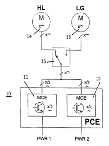
Figure 1 shows a highly simplified diagram of a sequential utilization, i.e.,
a
successive or alternate utilization, of common power electronics 10; 20 (PCE,
Power
Control Electronics) by different aircraft systems, namely a high lift system
(High
Lift FAS) and a landing gear (Landing Gear) that respectively contain
servomotors
or drive motors 14, 24 and 15; 25 that are supplied by the common power
electronics
10; 20 and selectively connected, i.e., in accordance with the respective
requirements, to the power electronics 10; 20 by a switching device 13; 23 in
order to
be supplied with energy. The power supply of the power electronics 10; 20 is
realized with various redundant power supplies PWR (Power) 1 to 3 as
schematically
indicated in Figure 1.
Figures 2a) and b) respectively show a circuit diagram of a system according
to one
embodiment of the invention, in which common power electronics 10 abbreviated
in
the form of PCE (Power Control Electronics) are utilized sequentially, for
example,
by the landing flap system and the landing gear, namely in the fully
functional
normal operating mode.
The device for redundantly supplying several electric servomotors or drive
motors
14, 15, in this case two motors, by a common power electronics unit (PCE) 10
contains a number of electronic motor control units 11, 12 abbreviated in the
form of
MCE (Motor Control Electronics), in this case two motor control units, and a
switching device 13 for selectively connecting the motor control units 11, 12
to the
motors 14, 15 in order to supply these motors with energy; see the motor 14 in
Figure
2a) and the motor 15 in Figure 2b). When the electronic motor control units
11, 12
are fully functional, the electric motors 11, 12 are respectively operated
with nominal
power.
The two motor control units 11, 12 are respectively provided for generating a
part of
x phases, namely half x/2 of x phases, with which the motors are operated,
wherein
CA 02629552 2008-05-13
WO 2007/068451 PCT/EP2006/011955
-10-
the two motors 14, 15 are operated with the still intact phases of the motor
control
units 11, 12 by the switching device 13 if partial failure of the motor
control units 11,
12 occurs, i.e., both of the motors 14, 15 are operated with the still
available residual
power of the motor control units 11, 12 by the switching device 13 if partial
failure
of the motor control units 11, 12 occurs.
Consequently, the PCE 10 is "intrinsically redundant", i.e. the total number
of phases
x is divided over two separate and autonomous converters (MCEs), i.e., the
motor
control units 11, 12 that respectively generate half of the phases. This not
only
prevents total failure if an individual defect occurs, but simultaneously
makes it
possible to reduce the weight in comparison with a solution featuring two
independent PCEs that respectively have the full number of phases.
The embodiments in Figures 3a) and b) elucidate the effect of an individual
defect in
one of the two MCEs 11, 12. This results in the loss of half of the phase
conductors
in the PCE 10 and manifests itself in a degraded power deployment in the
consumer
systems--respectively indicated with x/2 in the respective figures--but does
not lead
to the total failure of one of the two systems. The term "intrinsic
redundancy" was
used in the example of a sequential utilization. The concept is not new per
se, but in
combination with a parallel utilization by several aircraft systems opens up
new
system design options with respect to weight and reliability. In this context,
it would
be conceivable to realize the following enhancements. If the number of phases
per
motor control unit (MCE) is doubled in the above-described example, i.e., if
each
MCE already represents a full-phase supply module for a motor, and the switch
is
modified in such a way that the phases of the modular motor controls (MCEs)
may
be collectively or separately switched through to one respective motor, it is
also
possible for two motors to simultaneously utilize a MCE module. In combination
with the above-described configuration for a sequential utilization, this
results in
entirely new configuration options. This train of thought forms the transition
to the
next embodiment, in which the simultaneous utilization of power electronics is
discussed in greater detail. The above-mentioned conventional central drive
system
CA 02629552 2008-05-13
WO 2007/068451 PCT/EP2006/011955
-11-
of the landing flaps that is abbreviated in the form of PCU (Power Control
Unit) and
features duplex electric motors situated in the fuselage is used as the
example for the
simultaneous utilization of power electronics and described below with
reference to
Figures 4 and 5a) to e). In this constellation, each of the two motors 24, 25
is excited
by a separate converter, i.e., a separate motor control unit 21, 22 (Motor
Control
Electronics-MCE) in the normal operating mode, wherein this corresponds, in
principle, to the supply of the conventional fully hydraulic Power Control
Unit
(PCU) by two independent hydraulic systems. A switching device 23 is provided
in
order to selectively connect the MCEs 21, 22 to the motors 24, 25 in
accordance with
the respective requirements. If one of the two MCEs 21, 22 fails, the still
intact MCE
is able to continue operating both motors 24, 25 with reduced power--if the
motor
topology is chosen accordingly. If individual windings in one of the two
motors are
damaged instead or in addition to the MCE, it would be possible to selectively
drive
the intact phases only or to fully drive the completely intact motor only as
long as the
respective phase(es) of both of motors are known. In this particular
embodiment, this
concept of a simultaneous utilization is intended as a "backup" only in case a
defect
of the described type occurs.
As initially mentioned, the internal design of the Power Control Unit (PCU)
was
intentionally realized with two full-phase MCEs 21, 22. It should be noted
that the
examples of a sequential utilization that were described with reference to
Figures 2a)
and b) as well as 3a) and b) featured Power Control Electronics (PCE) 10 that
consisted of several--in the described example two--complimentary units 11, 12
that
respectively supply only part of the phase conductors while the embodiment
with
simultaneous utilization described below with reference to Figures 4 and 5a)
to e)
features two complete and independent units 21, 22 that supply all phases.
It is quite obvious that the design of the PCE 10 according to the first
embodiment of
a sequential utilization may be transferred to the MCEs 21, 22 according to
the
second embodiment such that the defect tolerance and therefore the operative
states
could be once again significantly increased despite multiple defects. A
graphic
CA 02629552 2008-05-13
WO 2007/068451 PCT/EP2006/011955
-12-
representation of all possible combinations therefore was intentionally
omitted.
Different failure states of the arrangement shown in Figure 4 as well as the
handling
thereof are described below with reference to Figures 5a) to 5e).
Figure 5a): simultaneous utilization of the power electronics 20 during a
total failure
of the MCE 21. Both motors 24, 25 are supplied by the intact MCE 22. This
means
to cut in half the active phases per motor and the degradation of the power
output.
Figure 5b): partial failure of both MCEs 21, 22. This leads to the same result
as in
Figure 5a), but the supply is realized with the degraded MCEs 21, 22.
Figure 5c): partial failure of both motors 24, 25. Both MCEs are intact. The
result is
identical to that described above.
Figure 5d): total failure of the MCE 21 and partial failure of both motors 24,
25. The
MCE 22 supplies both motors 24, 25 with half the respective number of phases.
The
result is identical to that of Figure 5a) and b), respectively.
Figure 5e): partial failure of both MCEs 21, 22 and both motors 24, 25. The
motors
24, 25 are still supplied by the respective MCE 21 or 22 analogous to the
normal
operating mode. Only the power is degraded. The result is identical to that
described
above.
In the scenarios with motor failure described with reference to Figures 5c) to
e), it
was always assumed that partial failure of both motors 24, 25 occurred
although this
is highly unlikely. However, a defect in only one motor would lead to the same
result
because the defect would be detected and both motors would be reduced to the
power
consumption of the defective motor. The defective phase of the corresponding
motor
could be determined with measurements carried out during its operation.
CA 02629552 2008-05-13
WO 2007/068451 PCT/EP2006/011955
- 13 -
In summation, the described overall concept obviously results from the
consequent
implementation of the sequential utilization of a source by systems with short
load
cycle times. The resulting requirement for improved availability requires an
increased redundancy. This increased redundancy should not be associated with
the
conventional increase in weight and structural space in order to not endanger
the
competitiveness of a system solution. The integrated redundancy that is based
on
autonomizing and partitioning the original function not only fulfills the
restrictive
requirements with respect to the structural space and the weight, but also
makes it
possible to realize additional system configurations for various defect
scenarios that
increase the flexibility and overall availability of the system.
It should be noted that the term 'comprising' does not exclude other elements
or
steps and the 'a' or 'an' does exclude a plurality. Also elements described in
association with different embodiments may be combined.
It should be noted that the reference signs in the claims shall not be
construed as
limiting the scope of the claims.
CA 02629552 2008-05-13
WO 2007/068451 PCT/EP2006/011955
-14-
List of Reference Symbols
10; 20 Power electronics unit (PCE)
11; 21 Motor control unit (MCE)
12; 22 Motor control unit (MCE)
13; 23 Switching device
14; 24 Motor
15; 25 Motor