Note: Descriptions are shown in the official language in which they were submitted.
CA 02629583 2011-05-25
POCKET WITH SECURE DIVIDERS
10 BACKGROUND
The present invention is directed to a pocket, and more particularly, to a
pocket having
dividers securely received therein.
Pockets may be used to store various items such as loose papers, writing
utensils, or the
like. Such pockets may include a divider or dividers positioned therein so
that the contents of the
pocket can be easily compartmentalized and organized. In addition, it may be
desired to provide
a secure attachment means such that the dividers are securely attached to the
pocket and are not
easily removed or torn.
SUMMARY
The present disclosure in one aspect provides a pocket assembly that includes
a major
panel and a pocket panel coupled together to define a pocket therebetween. A
divider is placed
in the pocket to partition the pocket into two or more compartments. The
divider comprises a
securing element secured to at least one of the major and pocket panels.
In one embodiment, the securing element may be a tab extending from the
divider and
attached to the at least one of the major and pocket panels. The pocket may be
provided at its
bottom with an opening while the tab may extend through the opening and may be
attached to
the outside surface of the at least one of the major and pocket panels. The
tab may be folded flat
against the outside surface of the at least one of the major and pocket panels
to be atta:ched
1
CA 02629583 2008-04-21
In another embodiment, the divider may include at least one divider panel, and
the tab
may be coupled to the at least one divider panel along its lower edge. The
divider may include
two or more divider panels. First and second ones of the two or more divider
panels may be
foldably connected together along their common lower edge, and the tab may be
formed from the
first divider panel and joined to the second divider panel along the lower
edge. The first and
second divider panels may be folded about the common lower edge into a face-to-
face
relationship such that the tab protrudes downwardly from the second divider
panel. Alternatively,
the two or more divider panels may be separate panels, and each of them may
have the tab so
that the each divider may be individually coupled to the at least one of major
and pocket panels
by the tab of the each divider panel.
In a further embodiment, the major panel may include a set of openings formed
therethrough. The openings may be positioned and aligned to allow the pocket
assembly to be
coupled to a binding mechanism.
In a still further embodiment, the pocket panel may be generally rectangular
in shape.
The pocket panel may be securely coupled to the major panel along at least two
secured outer
edges while leaving at least one free outer edge unattached to the major
panel. The assembly
may further comprise a side flap coupling one of the at least two secured
outer edges of the
pocket panel to the major panel to allow the pocket to expand.
The present disclosure in a second aspect provides a portfolio which includes
a major
panel and a pocket panel coupled together to define a pocket between the
respective inside
surfaces of the major and pocket panels. A divider is received in the pocket.
The pocket panel is
coupled to the major panel along its lower edge to define the bottom of the
pocket. The pocket is
provided at its bottom with an opening. The divider comprises a tab extending
outwardly of the
pocket through the opening and is attached to the outside surface of one of
the major and pocket
panels.
2
CA 02629583 2008-04-21
In one embodiment of this aspect, the pocket panel may be foldably coupled to
the major
panel along the lower edge. The opening may be formed along the lower edge,
and the tab may
be folded about the lower edge onto the outside surface of the one of the
major and pocket panels
to be attached to the outside surface.
In another embodiment, the portfolio may further include a second major panel
foldably
coupled to the first major panel. A spine may be positioned between the first
and second major
panels. Further, a binding mechanism may be mounted to one of the spine and
either one of the
=
first and second major panels. A second pocket panel may be coupled to the
second major panel
to define a second pocket between the second major panel and the second pocket
panel. In such
an embodiment, a second divider may be received in the second pocket. The
second pocket
panel may be provided at the bottom thereof with an opening. The second
divider may comprise
a tab extending outwardly of the second pocket through the opening of the
second pocket. The
tab of the second divider may be attached to the outside surface of one of the
second major and
second pocket panels.
In a further embodiment, the portfolio may further comprise a closure flap
pivotally
coupled to the upper edge of the first major panel. The closure flap may
include a locking
tongue while the pocket panel may have a tongue socket engageable with the
locking tongue.
BRIEF DESCRIPTION OF THE DRAWINGS
Fig. 1 is a front perspective view of a portfolio in a closed position
incorporating a
pocket/divider design;
Fig. 2 is a front perspective view of the portfolio of Fig. 1 shown in its
open position;
Fig. 3 is a side cross-section taken along line 3-3 of Fig. 2;
Fig. 4 is a side cross-section taken along line 4-4 of Fig. 2;
Fig. 5 is a top view of a blank which can be used to form the portfolio of
Figs. 1 and 2;
Fig. 6 is a top view of a blank which can be used to form the dividers shown
in Figs. 2-4;
Fig. 7 is a front perspective view of the dividers of Fig. 6, shown in a
partially folded
state;
3
CA 02629583 2008-04-21
Fig. 8 is a front perspective view of the folded dividers of Fig. 7 positioned
above the
assembled portfolio of Fig. 5;
Fig. 9 is a front perspective view of the dividers and the portfolio of Fig. 8
in an
assembled condition;
Fig. 10 is a front perspective view of a portfolio and a single-ply divider
exploded away
from the portfolio;
Fig. 11 is a front perspective view of another portfolio utilizing a pocket
and divider
design; and
Fig. 12 is a front perspective view of the portfolio of Fig. 11 shown in an
opened position
with the dividers exploded away from the pocket.
DETAILED DESCRIPTION
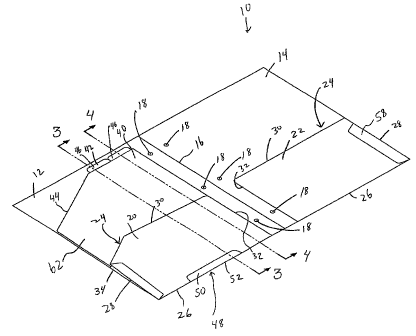
Figs. 1-4 illustrate a portfolio, generally designated 10, including a pair of
opposed
major panels 12, 14. The major panels 12, 14 are pivotally attached to each
other along a central
fold line 16. In this manner, each major panel 12, 14 is independently
pivotable about the fold
line 16 such that the portfolio 10 is moveable between a closed position (Fig.
1) wherein the
major panels 12, 14 are generally parallel, aligned and face each other, and
an open position (Fig.
2) wherein the major panels 12, 14 lay generally flat and coplanar and do not
face each other.
If desired, a spine (not shown) may be positioned between the major panels 12,
14.
Further, if desired, a binding mechanism (not shown) may be mounted to the
spine or to either of
the major panels 12, 14. In the illustrated embodiment, each of the major
panels 12, 14 includes
a set of openings 18 formed theretlu-ough, wherein the openings 18 are
positioned and aligned to
allow the portfolio 10 to be coupled to a three-ring binding mechanism or the
like.
A generally rectangular pocket panel 20, 22 is attached to the inner surface
of each
=25 associated major panel 12, 14 to define a pocket 24 therebetween. More
particularly, each
pocket panel 20, 22 may be securely coupled to the underlying major panel 12,
14 along two
secured edges (i.e. a bottom edge 26 and an outer edge 28), leaving two free
edges (top edge 30
and inner edge 32) along which the associated pocket 24 can be accessed. In
the illustrated
embodiment, an expandable gusset or side flap (such as an accordion-style
gusset) 34 is coupled
to the outer edge 28 of the pocket panel 20 to allow the associated pocket 24
to expand as
desired.
4
CA 02629583 2008-04-21
A set of dividers 40,42 may be positioned in the pocket 24. In the illustrated
embodiment, each of the dividers 40, 42 is generally rectangular, having an
angled corner 44 and
a protruding tab 46. In the illustrated embodiment, each divider 40, 42.is
made of a generally
transparent material although, if desired, the dividers 40, 42 can be made of
opaque or various
other materials.
Each divider 40, 42 may have a width (i.e. in the left-to-right direction of
Figs. 2 and 5)
about equal to the width of the associated pocket panel 20/major panel 12 to
allow the contents
of the pocket 24 to be completely divided/segregated. More particularly, in
one embodiment,
each divider 40,42 may have a width within at least about 10% or at least
about 20%, or at least
about 30% of the width of the associated pocket panel 20 and/or major panel
12. Furthermore,
each divider 40,42 may have a height (i.e. extending in the top-to-bottom
direction of Figs, 2
and 5) close to the height of the portfolio 10/major panels 12, 14 such that
the dividers 40, 42 can
extend through a stack of loose leaf papers of various heights stored in the
associated pocket 24.
Thus, in one embodiment, each divider 40, 42 may have a height within at least
about 10%, or at
least about 20%, or at least about 30%, of the height of the portfolio 10
and/or associated major
panel 12.
The pocket 24 defined by pocket panel 20 has a narrow opening or slit 48
formed along
its bottom edge 26, as best shown in Figs. 5 and 8. At least one of the
dividers 40,42 includes a
tab portion 50 which protrudes through the opening 48 and is folded flat
against the outer surface
of the pocket panel 20. The tab 50 may then be attached to the underlying
pocket panel 20 to
securely couple the tab 50/divider(s) 40,42 to the portfolio 10/pocket panel
20. The tab 50 can
be attached to portfolio 10/pocket panel 20 by any of a wide variety of
methods, such as heat
welding, sonic welding, stitching, adhesives, staples, rivets or other
mechanical fasteners, etc.
The tab 50 may have a relatively long length (i.e. extending along the left-to-
right
direction of Fig. 2) to ensure adequate coupling strength. More particularly,
the tab 50 may
extend along at least about 10%, or at least about 20% or at least about 30%,
or at least about
40% of the width (i.e. extending in the left-to-right direction of Fig. 2) of
the associated major
panel 12, pocket panel 20 and/or divider 40, 42. The opening 48 may have a
length that is about
equal to the length of the associated tab 50 (i.e. within about 10% of the
length of the tab 50)
such that the opening 48 closely receives the tab 50 therethrough.
5
CA 02629583 2008-04-21
In this manner, the tab 50 securely retains the divider(s) 40, 42 to the
portfolio 10/pocket
panel 20. More particularly, the tab 50 provides an attachment structure that
can be easily
accessed and formed during manufacturing/assembly. Furthermore, because the
tab 50 is folded
about a bottom edge 26 of the pocket panel 20, the fold 52 provides further
secure attachment.
For example, the fold 52 of the tab 50 may accommodate stresses if the
divider(s) 40, 42 are
attempted to be pulled upwardly out of the associated pocket 24.
In order to assemble the portfolio of Figs. 1-4, in one embodiment the blank
54 of Fig. 5
may be provided. Each pocket panel 20, 22 may be pivoted about the lower edge
26 of the
associated major panel 12, 14 such that the pocket panels 20, 22 lay generally
flat against the
associated major panel 12, 14. The gusseted side flap 34 and opposite side
flap 58 are then
pivoted inwardly until each side flap 34, 58 lays on top of the associated
pocket panel 20,22.
The side flaps 34, 58 are then attached to the associated pocket panel to
complete the pockets 24
and provide the portfolio 10 shown in, for example, Fig. 8.
Next, as shown in Fig. 6, in one embodiment a blank 60 for forming the
dividers 40, 42
may be provided. In the illustrated embodiment, the dividers 40, 42 are formed
from a single,
unitary piece of sheet-like material 62. A generally "U"-shaped cut 64 is
formed in the blank 60
to define the tab 50 which is positioned adjacent to a central fold line 52 of
the blank 60. Next,
as shown in Fig. 7, the blank 60 is folded about the central fold line 52 such
that the tab 50
protrudes downwardly from the dividers 40, 42. Thus, in the illustrated
embodiment, the tab 50
is formed as a single piece that is unitary with at least one divider 40, 42,
or with both dividers
40, 42.
Next, as shown in Fig. 8, the assembled dividers 40, 42 are positioned above
the
assembled portfolio 10 and the dividers 40, 42 are inserted into the
associated pocket 24 such
that the tab 50 protrudes through the opening 48 (Fig. 9). The tab 50 is then
folded upwardly and
coupled to the outer surface of the pocket panel 20, resulting in the assembly
shown in Fig. 2.
However, the tab 50 could alternately be folded in the opposite direction such
that the tab 50
wraps around the outer surface of the major panel 12.
The portfolio 10 (i.e. including major panels 12, 14, pocket panels 20, 22,
side flaps 34,
58, spine, etc.), along with the dividers 40, 42 can be made of any of a wide
variety of materials,
including but not limited to plastic (such as polypropylene or vinyl),
cardboard, paperboard,
plastic encased cardboard, etc. In addition, the components of the portfolio
10 and dividers 40,
6
CA 02629583 2011-05-25
including but not limited to plastic (such as polypropylene or vinyl),
cardboard, paperboard,
plastic encased cardboard, etc. In addition, the components of the portfolio
10 and dividers 40,
42 can be attached/assembled by any of a wide variety of methods, such as heat
welding, sonic
welding, stitching, adhesive, staples, rivets or other mechanical fasteners,
etc. Further, while the
illustrated embodiment shows only pocket panel 20 receiving the dividers 40,
42 therein, if
desired, both pocket panels 20, 22 or only pocket panel 22 may receive the
dividers 40, 42.
Fig. 10 illustrates another embodiment of the invention, wherein only a single
divider 40
having a tab 50 is configured to be coupled to the portfolio. If desired,
multiple of the single-ply
dividers 40 of Fig. 10 can be coupled to the portfolio 10, wherein each
divider 40 includes its
own associated tab 50. This arrangement may provide greater strength in that
each divider 40 is
individually coupled by its own tab 50. However, the embodiment shown in Figs.
6 and 7
(wherein two dividers 40, 42 share a tab 50) may be advantageous that only a
single blank 60
and relatively few steps are required to produce a dual divider assembly.
Figs. 11 and 12 illustrate another embodiment of the invention wherein the
portfolio 70
includes a major panel 12, a pocket panel 20 defining a pocket 24
therebetween, and a pair of
dividers 40, 42 received in the pocket 24. In this embodiment, the pocket
panel 20 is relatively
large, having a surface area of about equal to the surface area of the major
panel 12. The pocket
panel 20 is secured to the underlying major panel 12 about bottom edge 26 and
side edge 28
thereby leaving top edge 30 and inner edge 32 as free edges. A closure flap 72
is pivotally
coupled to an upper edge of the major panel 12.
The closure flap 72 may include a tooth or locking element 74 that can be
inserted into
and through an opening or socket 76 of the pocket panel 20 to thereby secure
the portfolio 70 in
a closed position. However, any of a variety of closure mechanisms, such as
hook-and-loop
fasteners (such as VELCRO ), clasps, hooks, loops, elastic components,
brackets, magnets,
interengaging geometries or the like may be used to retain the closure flap 72
in a closed
position. The dividers 40, 42, having a configuration and assembly similar to
the dividers 40, 42
shown in Figs. 6 and 7 and described above, may be received in the pocket 24
and coupled to the
pocket 24 by the tab 50 extending through the opening 48 of the pocket 24. In
the embodiment
shown in Figs. 11 and 12, the tab 50 is folded rearwardly about the major
panel 12 and attached
thereto, such that the tab is generally not visible in Fig. 11.
7
CA 02629583 2008-04-21
The pocket/divider design provides an assembly that can be quickly and easily
manufactured, yet
provides a secure attachment mechanism due to the folded and attached nature
of the tab.
Having described the invention in detail and by reference to the various
embodiments, it
should be understood that modifications and variations thereof are possible
without departing
from the scope of the claims of the present application.
One embodiment of the present invention provides a pocket assembly including
first and
second generally flat, parallel panels. The first panel is coupled to the
second panel at least
partially along at least one edge, and is not coupled to the second panel at
least partially along
another edge, to define a pocket therebetween. The pocket includes an opening
formed
therethrough. A divider including a tab is received in the pocket such that
the tab extends
through the opening and is attached to the pocket to thereby attach the
divider to the pocket.
8